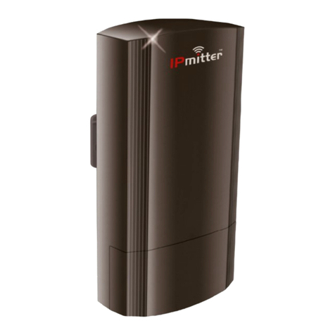
IPmitter IPMIT204 User manual

xIPMIT204
I
© 2022 System Q Ltd
IPmitter.com
Table of Contents
Part 1 Introduction 1
Part 2 User Information 1
Part 3 Powering & Controls 2
Part 4 Bridge Options 3
1 Standard WiFi Bridge Setup ........................................................................................... 3
2 "One to Many" WiFi Link ................................................................................................ 4
3 Multiple Pairs ................................................................................................................. 5
Part 5 Pairing 6
1 Example - Standard WiFi Bridge .................................................................................... 7
2 ERR Code or P-95 ........................................................................................................... 7
3 Example - One to Many .................................................................................................. 8
4 Example - Multiple Pairs ................................................................................................ 9
Part 6 Default Settings 10
Part 7 Browser Interface 11
1 Login ............................................................................................................................ 11
2 Home ............................................................................................................................ 12
3 Wizard .......................................................................................................................... 14
Repeater Mode .............................................................................................................................................. 15
AP Mode (Access Point) .............................................................................................................................. 19
4 CPE ............................................................................................................................... 22
5 WiFi .............................................................................................................................. 23
2G WiFi ............................................................................................................................................................. 23
Repeater Settings ......................................................................................................................................... 24
MAC ACL ........................................................................................................................................................ 24
WiFi Timer Off ................................................................................................................................................ 25
Advanced ........................................................................................................................................................ 25
6 Network ........................................................................................................................ 26
LAN Settings .................................................................................................................................................. 26
VLANSettings ............................................................................................................................................... 27
Cloud Server Settings ................................................................................................................................. 27
7 Manage ......................................................................................................................... 28
Configure ....................................................................................................................................................... 28
Reboot ............................................................................................................................................................. 29
Modify Password .......................................................................................................................................... 30
Upgrade .......................................................................................................................................................... 31
Time ................................................................................................................................................................ 32
Log ................................................................................................................................................................... 33
Part 8 Troubleshooting 34

Contents
II
© 2022 System Q Ltd
IPmitter.com
1 Pairing Issues ............................................................................................................... 34
2 Signal strength of P-095 ................................................................................................ 34
3 IP camera not working through IPmitter ....................................................................... 34
4 Not powering up ........................................................................................................... 35
5 Poor image quality or streaming speed ........................................................................ 35
6 Issueswith Internet data passthrough .......................................................................... 35
7 Signal low - different siteswith affect the range .......................................................... 36
8 Cannot login to the IPmitter browser interface ............................................................. 37
Part 9 Extra Resources 42
1 Tech Tips ...................................................................................................................... 43
Part 10 Specifications 44
Part 11 Conditions 45
Index 0

20/06/2022
xIPMIT204
1IPmitter.com
Introduction
The budget IPmitters have a data transfer rate of 300Mbs, using the 2.4Ghzband,
this is aimed at cost conscious installations.
The IPmitter works in2 modes withLED pairing, Repeater mode and AP mode, the
Host acts as the Access point (AP) and the client sets up as the repeater to provide
a WiFi Bridge betweenthe two.
IPMIT204 Canbe powered using 48 PoE (Not supplied) or canbe powered using
12V DC (Not supplied).
User Information
The connections to the must be cleanand dry, and not exposed to moisture or
excessive dust.
Do not touch the any of its connections with wet hands.
Ensure the power is switched off to the IPmitter if not inuse for a long period of
time.
There are no user serviceable parts inthe IPmitter and opening or attempting to
repair the product will void the warranty.
Onlyuse a 12V DC Regulated PSU(atleast 500mA) or a 48V PoE Supply(also
knownas 802.3af).
Do notinstall or use the device ifthe power cable or network connectionis
damaged.

Powering & Controls
© 2022 System Q Ltd
2
IPmitter.com
Powering & Controls
Powering
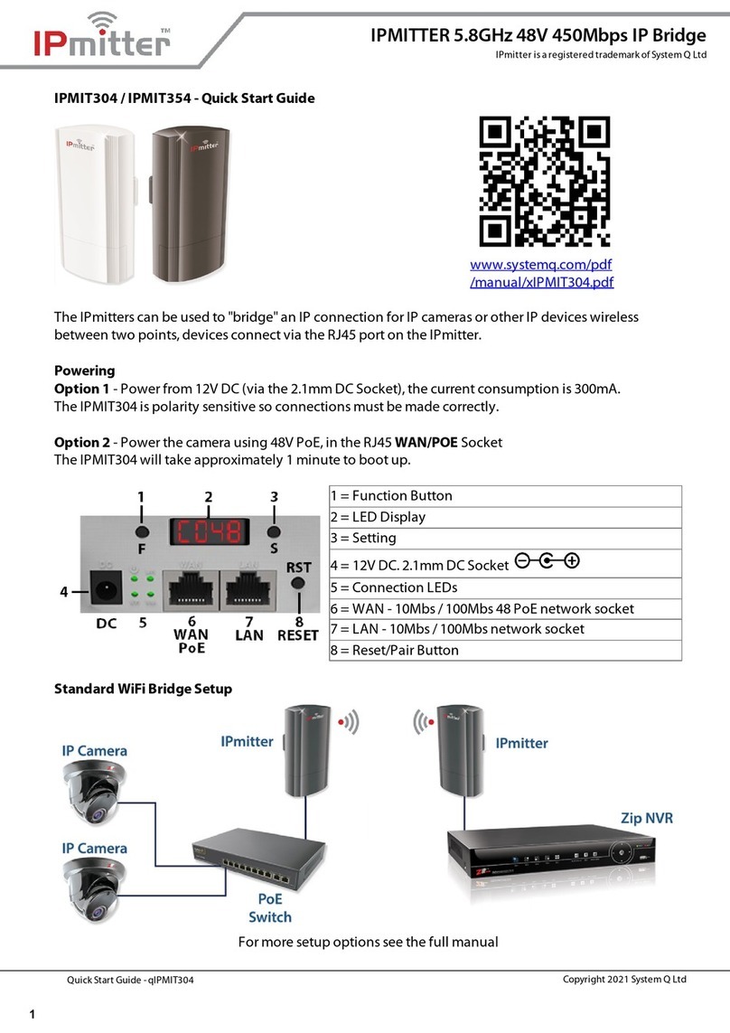
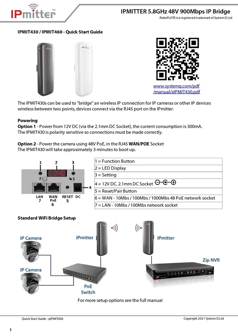
Option 1 - Power from 12V DC (via the 2.1mm DC Socket), the current consumption
is 300mA. The IPMIT304 is polaritysensitive so connections must be made correctly.
Option 2 - Power the camera using 48V PoE, inthe RJ45 WAN/POE Socket
Note: The IPMIT304 will take approximately 3 mintues to boot up.
1 = FunctionButton
2 = LED Display
3 = Setting Button
4 = 12V DC. 2.1mm DC Socket
5 = Status LEDs
6 = WAN- 10Mbps / 100Mbps 48 PoE
network socket
7 = LAN - 10Mbps / 100Mbps network
socket
8 = Reset/Pair Button
Status LEDs
PWR = Indicates onwhenpower is connected to the
IPmitter
WIFI= Indicates whenthere is WiFi connection
LAN / WAN = LAN and WAN light show network
connection and flicker to indicate activity

Bridge Options
© 2022 System Q Ltd
4
IPmitter.com
4.2 "One to Many" WiFi Link
Whenpairing, one unit needs to be set to "Host" and the manysender units need to
be set to "Client".
Note: When pairing multiple clients with one host,configure the clients to "C" and
the host to "H" and then pair the units. See Pairing for more information.
If a client has already been paired with the hostand another client is to be
added to the host, then down-power the existing client before attempting to
pair the next client.
For example:
6

20/06/2022
xIPMIT204
5IPmitter.com
4.3 Multiple Pairs
Whenpairing, the units needs to be set to "Client" and "Host" but withdifferent
channel numbers.
Note: When pairing multiple pairs each pair needs to be configured to a different
WiFi channel.
When pairing the second pair onwards, down-power the existing pair/s. See
Pairing for more information.
For example:
6

Pairing
© 2022 System Q Ltd
6
IPmitter.com
Pairing
Available Channels – Available channels 1-13
The IPmitters are sent out as default onH (Host).
One IPmitter needs to be set to H (Host) and the other to C (Client).
Ensure the IPmitters are paired up before installing inposition.
The units canbe down-powered and theninstalled inpositiononce paired.
IMPORTANT :
Keep bothIPmitters at least 2m apart during pairing, if the they are too
close theywill "de-sense" and not pair.
Iftheyare veryclose thenpoint them awayfrom eachother during pairing to
ensure theydo not "de-sense".
Do notattempt to pair bothIPmitters connected to the same PoE switch,
theywill detecta network loop and notpair.
Ifpairing is attempted withbothIPmitters connected to the same PoE
switch thendefault both units (press and hold rst button for at least 10
seconds).
Note: Super WDS mode is notused in the IPMIT204 models, as they nowuse
repeater and access point modes.
The Client is set to repeater mode and the Host is set to access point mode.
When pairing an older model IPMIT200 with a newmodel IPMIT204, then
the IPMIT200 is required to be set manually in the web interface to either
access point mode or repeater mode (depending on if being used as a client
or a host).

20/06/2022
xIPMIT204
7IPmitter.com
5.1 Example - Standard WiFi Bridge
Pairing on channel 007
1. Power bothIPmitters, and leave to boot up for at least 3 mins. During boot up they
will displaya rotating segment [_i]
2. Onone IPmitter (client), press the F (function) button and "H" will flash [H007].
Press the S (setting) buttonto change to [C007].
3. The whole displaywill flash to indicate the settings have beensaved,it will reboot
(cantake up to 3 mins) then the displaywill show[C007].
4. Now press the RST (reset) buttonfor 1 second on bothIPmitters [H007]
[C007].
The displaywill change to a P with a rotating segment whilst pairing [P __]. Pairing
cantake up to 5 minutes.
The displaywill showP and a value once paired [P0 10] [P0 12].
5.2 ERR Code or P-95
Note: The strength will range P-01 (Good) to P-75 (Poor).
If ERR shows thenthe IPmitters have not paired
Reset bothIPmitters, holding the R (reset) button downonbothIPmitters for 10
seconds. Once both units have booted back up, thentrythe pairing process again.
Note: Ensure the units are notplugged into the same switch/ network during pairing.
If P-95 shows the the IPmiiters have either not paired or theyhave lost signal.
1. Check the pairing > Reset bothIPmitters,holding the R (reset) buttondownon
bothIPmitters for 10 seconds.Once bothunits have booted back up,thentrythe
pairing process again.
2. BetweenP-070 and P-095 is too low for transmission> Trythe pairing process
with the devices closer together.

Pairing
© 2022 System Q Ltd
8
IPmitter.com
5.3 Example - One to Many
Pairing on channel 007
1. Power onall the IPmitters, and leave to boot up for at least 3 mins. During boot up
theywill displaya rotating segment [_i]
2. Onclient IPmitters, press the F (function) button and "H" will flash [H007]. Press
the S (setting) buttonto change to [C007].
3. The whole displaywill flash to indicate the settings have beensaved,it will reboot
(cantake up to 3 mins) then the displaywill show[C007].
4. Now press the RST (reset) buttonfor 1 second onthe IPmitters [H007] [C007]
[C007].
The displaywill change to a P with a rotating segment whilst pairing [P __]. Pairing
cantake up to 5 minutes.
The displaywill showP and a value once paired [P0 10] [P0 12] [P0 1 1].
Note: If a client has already been paired with the host and another client is to be
added to the host, then down-power the existing client before attempting to pair the
next client.

20/06/2022
xIPMIT204
9IPmitter.com
5.4 Example - Multiple Pairs
Pairing on channel 007 and 010
1. Power one pair of IPmitters, and leave to boot up for at least 3 mins. During boot
up theywill displaya rotating segment [_i]
2. Onone IPmitter (client), press the F (function) button and "H" will flash [H007].
Press the S (setting) buttonto change to [C 007].
3. The whole displaywill flash to indicate the settings have beensaved,it will reboot
(cantake up to 3 mins) then the displaywill show[C007].
4. Now press the RST (reset) buttonfor 1 second on bothIPmitters [H007]
[C007].
The displaywill change to a P with a rotating segment whilst pairing [P __]. Pairing
cantake up to 5 minutes.
The displaywill showP and a value once paired [P0 10] [P0 12].
5. Down-power the paired units and thenboot up the next pair.
6. On one IPmitter (client), press the F (function) button and "H" will flash [H007].
Press the S (setting) buttonto change to [C007].
7. The whole displaywill flashto indicate the settings have beensaved,it will reboot
(cantake up to 3 mins) then the displaywill show[C007].
8. Onthe Host, press the F (function) button two times. Press the S (setting) button
until the displayshows [H0 10].
9. Now press the RST (reset) buttonfor 1 second on bothIPmitters [H0 10]
[C007].
The displaywill change to a P with a rotating segment whilst pairing [P __]. Pairing
cantake up to 5 minutes.
The displaywill showP and a value once paired [P0 10] [P0 12].
10. Power the firstpair of IPmitters back up and check to ensure the two pairs work
correctly.

Default Settings
© 2022 System Q Ltd
10
IPmitter.com
Default Settings
The defaultsettings for the IPmitter:
IP Address = 192.168.1.123
Web Interface Password = ipmitter (lower case)
(These are shownonthe label on the back of the unit)
Default WiFi key = 66666666
Whenthe IPmitters are paired one IP address will always be onthe default and the
others willbe automaticallyassigned (via GHCP).
The IP address of the unit canbe found bypressing the F buttonuntil the display
changes to Axxxthe 3 characters after the A indicate the lastsegment of the IP
address.
Unless youhave changed the IP address the first 3 segments will stillbe on
192.168.1.
Defaulting the IPmitter to factory settings - Press and hold the RST (Reset)
buttonon the IPmitter for 10 seconds.

20/06/2022
xIPMIT204
11 IPmitter.com
Browser Interface
The following sectiondescribes the browser interface used for advanced setup and
configuration.
Maintenance tasks suchas setting the IPmitter to automaticallyreboot, and setting
changes like setting the IP address and WiFi password.
Note: The browser interface is for advanced users only, incorrect use / setting could
result in an inoperable unit. Please proceed at your own risk.
7.1 Login
This is the mainloginscreen whichis displayed as whenlogged into the IPmitter on
a browser.
Enter the Web Interface Password = ipmitter (lower case).

Browser Interface
© 2022 System Q Ltd
12
IPmitter.com
7.2 Home
This screendisplays the status informationof the IPmitter.
Operation Mode - Whichmode the IPmitter is set to currently(AP Mode for host,
Repeater Mode for the client).
Flow - Shows the data flowto and from the unit.
Device Information - Shows the current resource usage.
Device Description - Allows for a custom set name for this IPmitter.
LAN Information - The current IP address and basic network information.
WiFi Information - The current Wireless informationonthe IPmitter, for the Host
(AP) if it is paired to a Client (Repeater) the status will show a red 1, to indicate the
number of connected devices.
As standard this page will displayfor the Host (AP Mode) when paired witha Client
(Repeater).

Browser Interface
© 2022 System Q Ltd
14
IPmitter.com
7.3 Wizard
Pairing canbe done using the buttons on eachIPmitter (see Pairing for more
information) or it canbe done via the Wizard.
For a "Standard WiFi Bridge Setup" one IPmitter needs to be set as AP Mode
(Access Point Mode) and another as Repeater Mode.
See Bridge Options for informationonwhichIPmitter needs to be set to AP Mode
and Repeater Mode.
6
3

20/06/2022
xIPMIT204
15 IPmitter.com
7.3.1 Repeater Mode
Repeater mode requires anexisting WiFi connectionfrom a router, access point or
other IPmitter.
The IPmitter thenconnects to the existing WiFi connectionand thenextends that
network via the LAN/ WAN RJ45 ports or via WiFi onthe repeating IPmitter.
Select Repeater Mode.
1. Enter settings for existing WiFi, these are the details of whichthis IPmitter will
connect to. (Either a router / access point / host IPmitter).
Repeater SSID is the WiFi network SSID this IPmitter is to connect to.To find the
network youwant to connect to press Scanand thenselectthe WiFi network name.

Browser Interface
© 2022 System Q Ltd
16
IPmitter.com
Lock BSSID is the Mac Address of the device being connected to, this field is
completed automatically.
Encryption is the type of Wireless Encryption used to access the WiFi network.
Password is the password used to access the WiFi network.
Bandwidth is the broadcasting bandwidthwhichthis wireless network uses.This
needs to set to matchyour router/ WiFi Bandwidth.
Pass through is set to off as default, mayneed to be enabled for network data
(Internet traffic) at the repeater end.
Select Next to confirm settings.
2. Enter the WiFi settings for the repeater.
WiFi Status controls the WiFi onthe repeater. Whenused purelyas anIP camera
bridge thenit is recommended to leave this optionoff. Whenenabled the repeater
will broadcastits ownWiFi network as wellas the existing WiFi network.
SSID sets the name of the WiFi network youwill see broadcastat the repeater. This
canbe the same as the existing WiFi network or unique to the repeater.
Hide your WiFi name? Enable so that whena wireless device searches the area
for the networks it will not be able detectthe WiFi name.
WiFi Password is the password used to access the Repeater WiFi network.

20/06/2022
xIPMIT204
17 IPmitter.com
A strong password consists of at least sixcharacters (and the more characters,the
stronger the password) that are a combinationof letters, numbers and symbols. This
canbe the same as the existing WiFi network or unique to the repeater.
Timing allows for a timed reboot or interval for the IPmitter.
Select Next to confirm settings.
3. Enter the LANSettings for the IPmitter.
IP Mode canbe set to either GHCP, static or DHCP. GHCP is set as standard, and
will receive anaddress (similar to DHCP, but will also assignanother IPmitter
connected to anavailable address), static IP address is a unique fixed address
whichyoucan assignto the IPmitter. DHCP will obtainthe address from the DCHP
server or the router and assignIPmitter withanaddress from the network.
LAN IP is a unique local IP address of the IPmitter thatidentifies the device onthe
local area network.
Subnet is the number that defines a range of IP address that canbe used onthe
network. This should matchother devices onthe network. The most commonsubnet
mask is 255.255.255.0
Gateway (or default gateway) is a router address connected to the localnetwork that
sends packets out of the localnetwork. This is normallythe local IP address of the
router.
Primary DNS is usuallythe Gateway(router's) local IP address.
Secondary DNS another DNS server address
Other manuals for IPMIT204
1
This manual suits for next models
2
Table of contents
Other IPmitter Network Hardware manuals