2
2.1
Installation
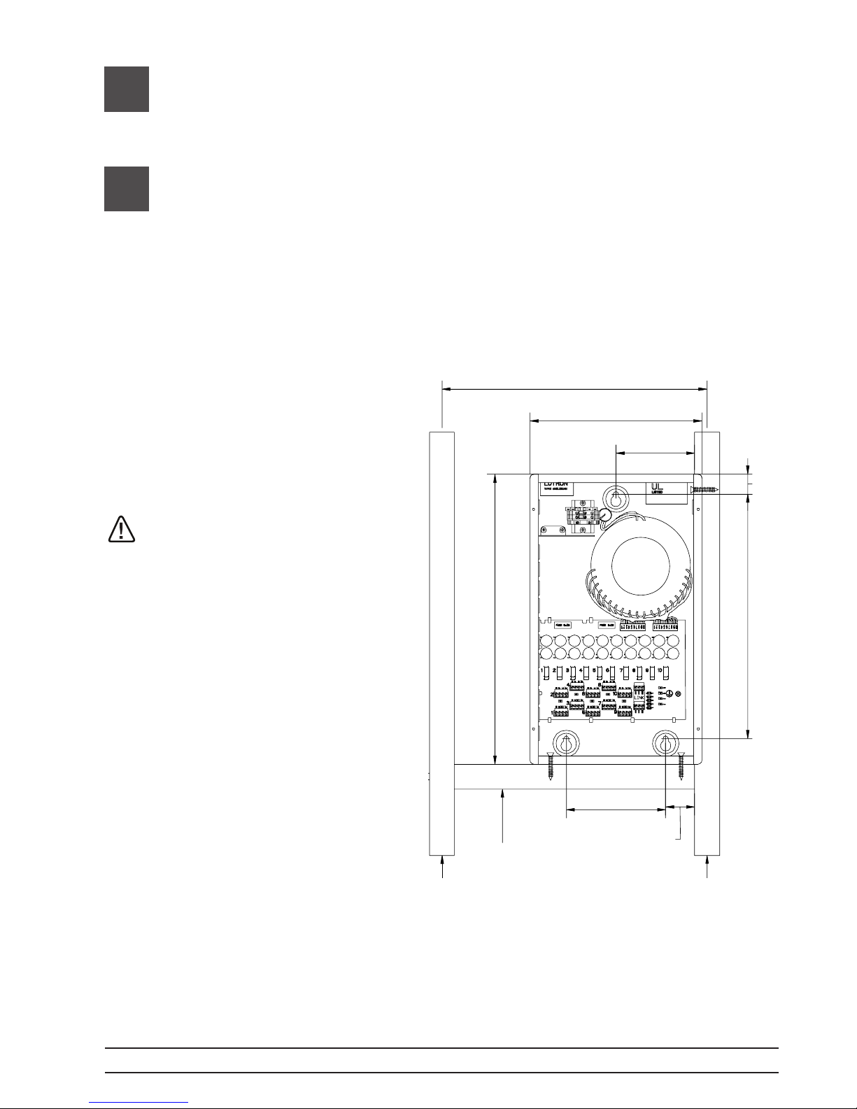
1. Mount QSPS-P2-10-60 using one of the following methods (mounting hardware is not
provided). Do not mount in any other orientation.
a. Surface Mount - Use the keyholes located on the back of the enclosure to fasten the
QSPS-P2-10-60 to the wall. Use fasteners rated for a 23 kg (50 lb) load. See illustration
of QSPS-P2-10-60 .
b. Recess Mount - Install a 50 mm x 100 mm (2 in x 4 in) board between the studs as
a bottom support. Fasten the QSPS-P2-10-60 to the right stud and bottom support
inserting fasteners through the mounting holes provided.
NOTICE: The equipment
is air-cooled. Mount in a
location where the vented
cover will not be blocked.
A minimum of 300 mm
(1 ft) is necessary.
WARNING: Risk of death
or serious injury. Lock the
supply breaker in the OFF
position before wiring to the
terminal blocks.
406 mm (16 in)
264 mm (10.4 in)
121 mm (4.8 in)
30 mm (1.2 in)
375 mm (14.8 in)
445 mm (17.5 in)
152 mm (6 in)
45 mm (1.8 in)
50 x 100 mm (2 x 4 in)
Bottom Support
2. Connect 230 V~ power wiring
into the QSPS-P2-10-60.
Remove one of the knockout tabs
on the top left side of the enclosure
near the input terminal blocks.
Insert a strain relief into the
knockout hole. Run the power wire
through the strain relief to the input
terminal blocks at the top left side
of the enclosure. Tighten terminal
blocks to 0.4 to 0.6 N•m (3.5 to
5 in-lbs).
Note: Maximum of (1) QSPS-P2-10-60 per
15 A Breaker. Maximum feed breaker size
of 15 Amps. Use only High-Magnetic breakers.
Page 2
Sivoia®QS QSPS-P2-10-60 (CE) Installation instructions