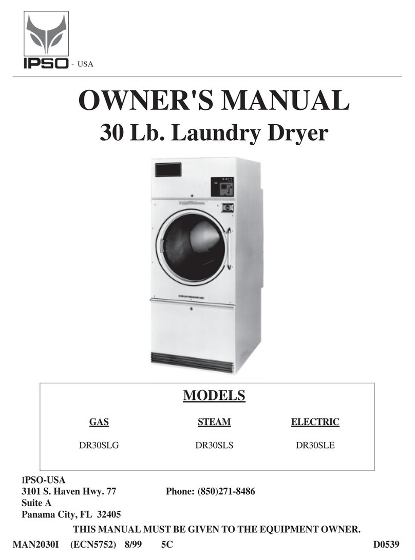
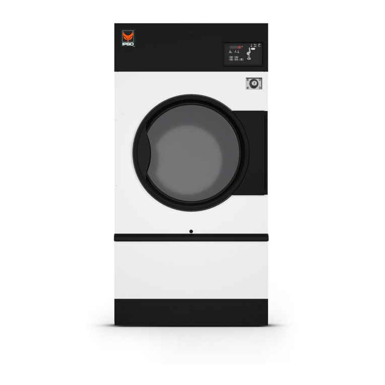
IPSO IPD30.1 User manual

Technical specifications
Installation instructions
Operating instructions
Maintenance
Electric
Steam
OWNER'S MANUAL
30 lb. IPD LAUNDRY DRYER
IPSO - USA
3101SouthHavenHighway77,SuiteA
PanamaCity,FL,32405
Phone:(850)271-8486
THIS MANUAL MUST BE GIVEN TO THE EQUIPMENT OWNER
MANIPD30.1 07/02
IPD30.1
- USA
Gas: Natural and LP
D0446

Page 2
IMPORTANT NOTICES—PLEASE READ
For optimum efficiency and safety, we recommend that you read the manual before operating the equipment. Store this
manualinafileorbinderandkeepforfuturereference.
WARNING: Purchasermust postthe followingnotice ina prominentlocation:
WARNING: Foryoursafety,theinformationinthismanualmustbefollowedtominimize
theriskoffireorexplosionortopreventpropertydamage,personalinjuryordeath.
-Donotstoreorusegasolineorotherflammablevaporsorliquidsinthe vicinityofthis
oranyotherappliance.
-WHATTODOIFYOUSMELLGAS
• Donottrytolightanyappliance.
• Donottouchanyelectricalswitch; donotuseanyphoneinyourbuilding.
• Cleartheroom,building,orareaofalloccupants.
• Immediatelycallyourgassupplierfromaneighbor'sphone.Followthegas
supplier's instructions.
• Ifyoucannotreachyourgassupplier,callthefiredepartment.
Installationandservicemustbeperformedbyaqualifiedinstaller,serviceagency
orthegassupplier.
WARNING: In the event the user smells gas odor, instructions on what to do must be posted in a
prominent location. This information can be obtained from the local gas supplier.
WARNING: Wear safety shoes to prevent injuries.
WARNING: Purchasermust postthe followingnotice ina prominentlocation:
FORYOURSAFETY
Donotstoreorusegasolineorotherflammablevapors
andliquidsinthevicinityofthisoranyotherappliance.
WARNING: A clothes dryer produces combustible lint and should be exhausted outside the building.
The dryer and the area around the dryer should be kept free of lint.
WARNING: Be safe, before servicing machine, the main power should be shut off.

Page 3
ATTENTION:L’ACHETEUR DOIT PLACER L’AVERTISSEMENT
SUIVANT DANS UN ENDROIT CLAIR ET VISIBLE:
ATTENTION:L’ACHETEUR DOIT PLACER L’AVERTISSEMENT
SUIVANT DANS UN ENDROIT CLAIR ET VISIBLE:
AVERTISSEMENT. Assurez-vousdebien
suivrelesinstructionsdonneesdanscette
noticepourreduireauminimumlerisque
d’incendieoud’explosionoupourevitertuot
dommagemateriel,touteblessureoulamort.
__Ne pas entreposerniutiliserd’essence ni
d’autresvapeursouliquidesinflammablesdans
levoisinagedecetappareiloudetoutautre
apparell.
__ QUE FAIRE SI VOUS SENTEZ UNE
ODEUR DEGAZ:
•Nepastenterd’allumerd’apparell.
• Netouchezaaucuninterrupteur. Nepas
vousservirdestelephonessetrouvantdans
lebatimentouvousvoustrouvez.
• Evacuezlapiece,lebatimentoulazone.
•Appelezimmediatementvotrefournisseurde
gazdepuisunvoisin. Suivezlesinstructions
dufournisseur.
•Sivousnepouvezrejoindrelefournisseur
degaz,appelezleservicedesincendies.
__l’installationetl’entretiendoiventetreassures
paruninstallateurouunserviced’entretien
qualifieouparlefournisseurdegaz.
POUR VOTRE SECURITE
Nepasentreposerniutiliserd’essence
nid’autresvapeursouliquides
inflammablesdanslevoisinagedecet
appareiloudetoutautreappareil.

Page 4
WARNING: Toavoidfire hazard,donot dry articlescontainingfoam rubber orsimilar
texture materials. Do not put into this dryer flammable items such as baby bed
mattresses, throw rugs,undergarments (brassieres, etc.) and other items which use
rubber as padding or backing. Rubber easily oxidizes causing excessive heat and
possible fire. These items should be air dried.
WARNING: Syntheticsolvent fumesfrom drycleaningmachines createacids whendrawn
through the dryer. These fumes cause rusting of painted parts, pitting of bright or plated
parts, and completely removes the zinc from galvanized parts, such as the tumbler basket. If
drycleaning machines are in the same area as the tumbler, the tumbler's make-up air must
come from a source free of solvent fumes.
WARNING: Do not operate without guards in place.
WARNING: Check the lint trap often and clean as needed but at least a minimum of once per day.
WARNING: Alterations to equipment may not be carried out without consulting with the
factory and only by a qualified engineer or technician. Only Manufacture’s parts may be
used.
WARNING: Remove clothes from dryer as soon as it stops. This keeps wrinkles from
setting in and reduces the possibility of spontaneous combustion.
WARNING: Besafe -shut mainelectrical powerand gassupply offexternally before
attempting service.
WARNING: Neveruse drycleaningsolvents, gasoline,kerosene,or otherflammable liquids
in the dryer. FIRE ANDEXPLOSIONWILLOCCUR. NEVERPUT FABRICS
TREATEDWITHTHESELIQUIDSINTOTHEDRYER.NEVERUSETHESE
LIQUIDSNEARTHEDRYER..
WARNING: Do not place items exposed to cooking oils in your dryer. Items contaminated
with cooking oils may contribute to a chemical reaction that could cause a load to catch fire.
WARNING: Never let children play near or operate the dryer. Serious injury could occur if a child
should crawl inside and the dryer is turned on.
WARNING: Never tumble fiberglass materials in the dryer unless the labels say they are machine
dryable. Glass fibers break and can remain in the dryer. These fibers cause skin irritation if they
becomemixedwithotherfabrics.
WARNING: Before operating gas ignition system - purge air from natural gas or propane gas lines
per manufacturer’s instructions.
WARNING: To reduce the risk of electric shock, disconnect this appliance from the power supply
before attempting any user maintenance other than cleaning the lint trap. Turning the controls to the
OFF position does not disconnect this appliance from the power supply.

Page 5
IPSO DRYER WARRANTY
TheIPSOManufacturingCompany(IPSO)warrantsallnewequipment(andtheoriginalpartsthereof)tobefreefromdefects
inmaterialor workmanship fora periodof three(3) yearsfrom the dateof salethereof toan originalpurchaser for use,except
as hereinafter provided. With respect to non-durable parts normally requiring replacement in less than three (3) years due to
normalwear andtear,and withrespectto allnewrepair orreplacementparts forIPSOequipment forwhich thethree(3) year
warrantyperiodhasexpired,orforallnewrepairorreplacementpartsforequipmentotherthanIPSOequipment,thewarranty
period is limited to ninety (90) days from date of sale. The warranty period on each new replacement part furnished by IPSO
in fulfillment of the warranty on new equipment or parts shall be for the unexpired portion of the original warranty period on
the part replaced.
With respect to electric motors, coin meters and other accessories furnished with the new equipment, but not manufactured
by IPSO, the warranty is limited to that provided by the respective manufacturer.
IPSO'stotalliabilityarisingoutofthemanufactureandsaleofnewequipmentandparts,whetherunderthewarrantyorcaused
byIPSO'snegligenceorotherwise,shallbelimitedtoIPSOrepairingorreplacing,atitsoption,anydefectiveequipmentorpart
returnedf.o.b. IPSO'sfactory, transportationprepaid,within theapplicable warrantyperiod andfoundby IPSOto havebeen
defective, and in no event shall IPSO be liable for damages of any kind, whether for any injury to persons or property or for
anyspecialor consequentialdamages. Theliability ofIPSOdoesnot includefurnishing (orpaying for)any laborsuch asthat
requiredtoservice,removeorinstall;todiagnosetroubles;toadjust,removeorreplacedefectiveequipmentorapart;nordoes
it include any responsibility for transportation expense which is involved therein.
ThewarrantyofIPSOiscontingentuponinstallationanduseofitsequipmentundernormaloperatingconditions.Thewarranty
is void on equipment or parts; that have been subjected to misuse, accident, or negligent damage; operated under loads,
pressures, speeds, electrical connections, plumbing, or conditions other than those specified by IPSO; operated or repaired
withother thangenuine IPSOreplacement parts;damaged byfire, flood,vandalism, orsuch othercauses beyondthe control
of IPSO; altered or repaired in any way that effects the reliability or detracts from its performance, or; which have had the
identificationplate, orserialnumber, altered,defaced, orremoved.
NodefectiveequipmentorpartmaybereturnedtoIPSOforrepairorreplacementwithoutpriorwrittenauthorizationfromIPSO.
Charges for unauthorized repairs will not be accepted or paid by IPSO.
IPSO MAKES NO OTHER EXPRESSED OR IMPLIED WARRANTY, STATUTORY OROTHERWISE,
CONCERNING THE EQUIPMENT OR PARTS INCLUDING, WITHOUTLIMITATION, A WARRANTY OF
FITNESS FOR A PARTICULAR PURPOSE, OR AWARRANTY OF MERCHANTABILITY. THE WARRANTIES
GIVEN ABOVE ARE EXPRESSLYIN LIEU OF ALL OTHER WARRANTIES, EXPRESSED OR IMPLIED. IPSO
NEITHERASSUMES, NOR AUTHORIZES ANY PERSON TO ASSUME FOR IT, ANY OTHERWARRANTY OR
LIABILITY IN CONNECTION WITH THE MANUFACTURE, USE OR SALE OFITS EQUIPMENT OR PARTS.
Forwarranty service,contact thedistributor fromwhom theIPSO equipment orpart waspurchased. Ifthe distributorcannot
be reached, contact IPSO.
IDENTIFICATIONNAMEPLATE
The identification nameplate is locatedon the rear wallof thedryer. Itcontains thedryer serialnumber, productnumber, modelnumber,
electrical specifications and other important data that may be needed when servicing and ordering parts, wiring diagrams, etc. Do not
removethisnameplate.

Page 6
Contents
SafetyInstructions ............................................................................................ 2-4
IPSODryerWarranty ....................................................................................... 5
Table of Contents.............................................................................................. 6
Symbols ............................................................................................................. 7
Unpacking / General Installation .................................................................... 8-9
Technical Data and Dimensions ......................................................................10-11
Electric Connections ........................................................................................ 12
Gas Connections ............................................................................................... 13
Gas Piping Installation ....................................................................................14-15
Gas service Installation Instructions ............................................................... 16
Gas Pipe Size Chart .......................................................................................... 17
Steam Piping Installation Instructions ............................................................18-19
Dryer Installation with Multiple Exhaust .......................................................20-21
Dryer Make-Up Air Requirements ................................................................... 22
Dryer Installation with Seperate Exhaust ....................................................... 23
Exhaust and Venting ........................................................................................ 24
Rules for Safe Operation of Dryer .................................................................... 25
Direct-Spark Ignition Operation...................................................................... 26-27
General Maintenance ....................................................................................... 28-29
Air Switch Adjustment ......................................................................................30
Operating Instruction for Double Timer.......................................................... 31
PARTS............................................................................................................... 32-58
Front View .....................................32
Access Door Assembly ...................33
Door Assembly ...............................34
Front Panel Assembly - OPL .........35
Front Panel Assembly - Coin ........36
Thermostat Assembly.....................37-38
PRO/HC SensorAssembly ............. 39
Mech. Coin Control Asm. ..............40
DX3 Coin Control Assembly .........41
DMP Coin Control Assembly ........42
2 Timer Control Assembly .............43
DX3 OPL Control Assembly .........44
DMP OPL Control Assembly.........45
PRO Control Assembly ..................46
PRO/HC Control Assembly ...........47
Lint Door Assembly .......................48
Basket & Spider Assembly.............49
Rear View.......................................50
Air Switch Assembly ......................51
Basket Bearings/Sheave Assy .......52
Motor & Fan Assembly .................53-54
Idler Assembly ...............................55
Rear Control Box Asm-Gas...........56
Rear Control Box Asm.-Elec.........57
Nat. Gas Heating Unit Asm. ..........58
L.P.GasHeatingUnitAsm............59
Steam Heating Unit Asm. ..............60
Electric Heating Unit Asm. ...........61
Recommended Spare Parts List ....62

Page 7
Rotationintwodirections
Rotationdanslesdeuxsens
Drehbewigunginzwei
Richtungen
Movimientorotativoenlos
dossentidos
Caution
Attention
Achtung
Atencion;precaucion
Directionofrotation
Sensdemouvementcontinu
DerotationDrehbewegung
inPfeilrichtungmovimiento
Giratorioorotatorioenel
sentidodelaflecha
Thefollowingsymbolsareusedinthismanualand/oronthemachine.
NOTE!
On
Marche
Ein
Conectado
Off
Arrêt
Aus
Desconectado
Hot!DoNotTouch
Heiß! NichtBeruhren
Hautetemperature!Nepas
toucher
Caliente!notocar
Start
Demarrage
Start
Arranquedeun
movimiento
Emissionofheatingeneral
Emissiondechaleuren
general
Warmeabgabeallgemein
Emisióndecalor
Cooling
Refroidissement
Kühlen
Enfriamiento
dangerousvoltage
tensiondangereuse
Gefährlicheelektrische
Spannung
tension peligrosa EndofCycle
DescriptionSymbol
SYMBOLS
Symbol

Page 8
Unpacking/General Installation (All Dryers)
Uponarrivaloftheequipment,anydamageinshipmentshouldbereported
tothecarrierimmediately.
Upon locating permanent location of a unit, care should be taken in
movementandplacementofequipment.
Seeoutlineclearancediagramsforcorrectdimensions.
Removeallpackingmaterialsuchas:tape,manuals,skid,etc.
Leveling:Usespiritlevelontopofdryer.Adjustlevelingboltsondryer(see
adjustablelevelingboltsinmaintenancesection).
Checkvoltageandamperesonratingplatebeforeinstallingthedryer.
Theconstructionofthedryerspermitsinstallationside-by-sidetosavespace
orto provide a wallarrangement.Position dryer for theleastamountof
exhaustpipingandelbows,andallowfreeaccesstotherearofdryerfor
futureservicingofbelts,pulleysandmotors.Installationclearancefromall
combustablematerialis0"ceilingclearance,0"rearclearance,and0"side
clearance.
Beforeoperatingdryer,openbasketdoorandremoveblockingbetween
frontpanelandbasket.Readtheinstructiontags,owner’smanual,warnings,
etc.
IMPORTANT
Openingtheclothesloadingdoordeactivatesthedoorswitch
toshutoffthemotors,fan,gas,steam,orelectricelement.To
restartthedryer,closethedoorandpressinthepushtostart
button.
IMPORTANT
This dryer is designed for a capacity maximum load.
Overloadingitwillresultinlongdryingtimesanddampspots
on some clothes.
IMPORTANT
Maximumoperatingefficiencyisdependentuponproperair
cIrculation. The lint screen must be kept cleaned daily to
insureproperaircirculationthroughoutthedryer.
IMPORTANT
Provideadequateclearanceforairopeningintothecombustion
chamber.
UNPACKING
GENERAL
INSTALLATION(ALL
DRYERS)

Page 9
Unpacking/General Installation (All Dryers)
Thedryerissodesignedthatwhenanoperatoropensthedryerdoor,the
basketandexhaustfanstop. Youcanexpectfastdryingfromthelaundry
dryer. Hot,dryairisproperlyandeffectivelymovedthroughthebasket
andexhaustedthroughalinttraptothe atmosphere. The dryercomes
equippedwithaninclinedself-cleaninglintscreen. Inthissystem,lint
accumulatesontheundersideofthescreenuntilablanketoflintfallsfrom
thescreentothebottomofthedryercabinet.Thelintshouldberemoved
dailyorasrequiredtopreventanover-accumulation.
IMPORTANT
Provideadequateclearanceforairopeningsintothecombustion
chamber.
Permanentpress,durablepressandothermoderndayfabricsrequirethe
carethatyourlaundrydryersnowprovide. Attheendofthedryingcycle,
atimed“Cool-Down”controlautomaticallytakesoverandcontinuesthe
rotationofthefanandbasketwithoutheatuntilthegarmentloadreaches
asafecooltemperature. Thisfunctionisperformed at theendofeach
dryingcycle.
Replacementpartsforthisdryerareavailablefromyourdistributororby
contractingthefactoryattheaddressorphonenumberprintedonthecover
pageofthismanual.
GENERAL
INFORMATION
DRYER
“COOL-DOWN”CYCLE
REPLACEMENT
PARTS

Page 10
HD30.1 lb. Dryer Dimensions - Standard Gas, Steam and Electric Heated
snoitacificepSerusaeM.S.U cirteM erusaeM
yticapaC )neniLyrD( .sbl03gk6.31
teksaB
retemaiDsehcni03mm267
htpeDsehcni
92mm737
emuloVtf9.11
3
retil633
tenibaC
thgieHsehcni27mm8281
htdiWsehcni33mm838
htpeDsehcni61/5-34mm0011
gninepOrooD
retemaiDsehcni8/5-22m
m575
thgiehgnidaoLsehcni2/1-13mm008
erutarepmeT
muminiM001
0
F83
o
C
mumixaM581
0
F58
0
C
rotoM
gnisrever-noN.P.H2/1Wk73.0
murD-gnisreveR.P.H2/1Wk73.0
naF.P.H2/1Wk73.0
tsuahxE
etaRwolFmfc526m2601
3
h/
retemaiDsehcni8mm302
sreyrDcirtcelE-.nnoCcirtcelE gnisreveR-noNgnisreveR
V802HP3-06A76A86
V042/022HP3-06/05A06/
55A06/55
V514/083HP3-05A73/43A63/33
V084HP3-06A03A13
sreyrDsaG,maetS-.nnoCcirtcelE gnisreveR-noNgnisreveR
V042-802
/511HP1-06/05A5.9A/N
V514/083HP3-06/05A4.1A3.4
V084HP3-06/05A3.1A5.2
rewoP
cirtcelEWk5.22h/lack053,91
saGh/utB000,011h/
lack027,72
maetSP.H.B5.4h/lack000,83
noitcennocmaetS
telnI"4/302ND
teltuO"2/151ND
noitcennoCsaG
noitcennoCsaG"2/151
ND
erusserPsaG"21-"5bm03-21
gnippihS snoisnemiD
)DxWxH( 84X63X87 sehcni 419X1891 mm9121X
thgieW
teN.celE/saG.sbl71
6gk082
ssorG.celE/saG.sbl256gk692
teNmaetS.sbl566gk203
ssorGmaetS.sbl007gk813

Page 11
IPD30.1 Dryer Dimensions - Gas
(Illustration)
IPSO

Page 12
Electric connection
Theconnectionneeds tobemadein thewiringboxat theback.Open thecoverplate
(G) in order to reach the connection clamps.
The connection cable needs to be brought in through the opening on the side of the
wiring box.
It is necessary to ground the dryer for your personal safety and to ensure a good
operation.
115 and 208-240 V - 1 ph
Themainswires(Ll)and(L2)shouldbeconnectedtothe2leftblocksandtheyellow/
green grounding wire (PE) should be connected to the grounding block.
208-240 and 480 V - 3 ph
The 3 mains wires (L1), (L2) and (L3) should be connected to the 3 left blocks and
theyellow/greengroundingwire(PE)shouldbe connectedto thegroundingblock.
380-415V - 3 ph
The 3 mains wires (L1), (L2) and (L3) should be connected to the 3 left blocks, the
blue neutral (N) should be connected to the right block and the yellow/green
grounding wire (PE) should be connected to the grounding block.
G
Dryersmustbeelectricallygroundedbyaseparate#14orlargergreenwirefromthegroundingterminalwithinthe
ServiceConnectionBox,toacoldwaterpipe.Inallcases,thegroundingmethodmustcomplywithlocalelectrical
coderequirements; or inthe absence oflocal codes, withthe National ElectricalCode,ANSI/NFPA70 or
the Canadian Electrical Code, CA C22.1.
Seewiringdiagramfurnishedwithdryer. Donotchangewiringwithoutconsultingthefactory,asyoumayvoid
thefactorywarranty.DONOTCONNECTTHEDRYERTOANYVOLTAGEORCURRENTOTHER
THANTHATSPECIFIEDONTHEDRYERRATINGPLATE.(Wiringdiagramislocatedonrearwallofdryer.)
Allpanelsmustbeinpositionbeforeoperationofdryer.
«Attention. Lorsdesopérationsd’entretien
des commandes, ètiqueter tous les fils avant
de les dèconnecter. Toute erreur de câblage
peut être une source de danger et de panne»
PE L1 L2 L3 N
208-240V
3 X 208-240V
3 X 380-415 + N

Page 13
The gas supply pipe should be connected to the union (I), which is on the right next
to the wiring box on the back.
It is very important to have the connections done by a qualified technician, in order to
make sure that the installation is effected in accordance with the prevailing standards
and instructions.
Thedryershould beconnectedtothe typeofgas,which isindicated ontheserialplate.
The use of too small gas pipes can result in unsufficient gas supply, which can lead to
a bad heating-up and a poor drying quality.
Whenthedryerisusedincombinationwithaweighingplatform,thegassupplypipe
hastobemadeofflexiblematerialtoallowtheweighingsystemtokeepmovingfreely.
Test all connections for possible leaks by means of a soap solution, but never with a
I
inordertoobtainagoodignition,heatingandconsequentlyagoodoperationingeneral.
After the gas supply has been connected, the gas tap in the dryer should beturned on
(clockwise).
flame.
It is important to work with the right gas pressure (see technical remarks)
Gas connection

Page 14
Gas Piping Installation
1. Theinstallationmustconformwithlocalcodes,orintheabsence
of local codes with the National Fuel Gas Code as, ANSI
Z223.1 or the CAN/CGA-B149, Installation Codes.
2. Checkidentificationnameplatefortypeofgasfordryer.
3. Checkthealtitudeofdryer.
4. Checkwithutilitiescompanyforpropergaspressureandgas
supplyline.
5. Naturalgasonly—checkthegaspressureinletsupplytodryer,
11”watercolumn(27.4mbar)maximum.Manifoldpressure—
3.5”watercolumn(8.8mbar)pressure.
6. L.P.gasonly—manifoldpressure—13”watercolumn(32.4
mbar)maximum.
CAUTION:Lowgaspressureandintermittentgaswillcause
gasignitionproblemsandinadequatedryingoflaundry.
GAS PIPING
INSTALLATION

Page 15
Gas Piping Installation (Illustrations)
Thedryerandit’sindividualshutoffvalvemustbedisconnectedfromthegassupplypipingsystemduring
anypressuretestingofthatsystemattestpressuresinexcessof1/2psi(.04bar).
Thedryermustbeisolatedfromthegassupplypipingsystembyclosingit'sindividualmanualshutoffvalve
duringanypressuretestingofthegassupplypipingsystemattestpressuresequaltoorlessthan1/2psi
(.04bar).

Page 16
Thesizeofthegasservicepipeisdependantuponmanyvariables,such
astees,lengths,etc.Specificpipesizeshouldbeobtainedfromthegas
supplier.Refertothe“GasPipeSize”chartinthismanualforgeneralgas
pipesizeinformation.
CAUTION:Gaslooppipingmustbeinstalledasillustrated
tomaintainequalgaspressureforalldryersconnectedtoa
single gas service
Other gas-using appliances should be connected upstream
fromtheloop.
WARNING:
LIQUIFIEDPETROLEUMGASESONLY!
Agaspressureregulatorforliquifiedpetroleumgasesisnotfurnishedon
thegasheatedclothesdryers.Thisregulatorisnormallyfurnishedbythe
installer.InaccordancewithAmericanGasAssociation(AGA)
standards,agaspressureregulator,wheninstalledindoors,mustbe
equippedwithaventlimiteroraventlinemustbeinstalledfromthegas
pressureregulatorventtotheoutdoors.
Gas Service Installation Instructions
GAS SERVICE
INSTALLATION
INSTRUCTIONS
GAS PRESSURE
REGULATOR FOR
LIQUIFIED
PETROLEUM GASES

Page 17
Gas Pipe Size Chart
TOTAL BTU/HR
(for LP Gas correct
total BTU/HR below by
multiplying by .6)
TOTAL
KCAL
HOUR
GAS PIPE SIZE FOR 1000 BTU (250 KCAL) NATURAL GAS
AT 7” (17.5 MM) W.C. PRESSURE
In figuring total length of pipe, make allowance for tees and elbows.
(150 ft.)
45,72 m
(125 ft.)
38,1 m
(100 ft.)
30,48 m
(75 ft.)
22,86 m
(50 ft.)
15,24 m
(25 ft.)
7,62 m
60,000
80,000
100,000
120,000
140,000
160,000
180,000
200,000
300,000
400,000
500,000
600,000
700,000
800,000
900,000
1,000,000
1,100,000
1,200,000
1,300,000
1,400,000
1,500,000
1,600,000
1,700,000
1,800,000
1,900,000
2,000,000
2,200,000
2,400,000
2,600,000
2,800,000
3,000,000
3,200,000
3,400,000
3,600,000
3,800,000
4,000,000
15000
20000
25200
30200
35200
40300
45300
50400
75600
100800
126000
151200
176400
202000
230000
250000
270000
300000
330000
350000
380000
400000
430000
450000
480000
504000
550000
605000
650000
705000
750000
806000
850000
907000
960000
1000000
3/4
3/4
3/4
3/4
3/4
3/4
1
1
1
1 1/4
1 1/4
1 1/2
1 1/2
1 1/2
2
2
2
2
2
2
2
2
2
2 1/2
2 1/2
2 1/2
2 1/2
2 1/2
2 1/2
2 1/2
2 1/2
3
3
3
3
3
3/4
3/4
3/4
1
1
1
1
1
1 1/4
1 1/4
1 1/2
1 1/2
2
2
2
2
2
2
2 1/2
2 1/2
2 1/2
2 1/2
2 1/2
2 1/2
2 1/2
2 1/2
3
3
3
3
3
3
3 1/2
3 1/2
3 1/2
3 1/2
3/4
3/4
1
1
1
1
1
1 1/4
1 1/4
1 1/2
1 1/2
2
2
2
2
2
2 1/2
2 1/2
2 1/2
2 1/2
2 1/2
2 1/2
2 1/2
3
3
3
3
3
3
3
3 1/2
3 1/2
3 1/2
3 1/2
3 1/2
3 1/2
3/4
1
1
1
1
1 1/4
1 1/4
1 1/4
1 1/2
1 1/2
2
2
2
2
2 1/2
2 1/2
2 1/2
2 1/2
2 1/2
2 1/2
2 1/2
3
3
3
3
3
3
3
3 1/2
3 1/2
3 1/2
3 1/2
3 1/2
3 1/2
4
4
3/4
1
1
1
1
1 1/4
1 1/4
1 1/4
1 1/2
1 1/2
2
2
2
2 1/2
2 1/2
2 1/2
2 1/2
2 1/2
2 1/2
3
3
3
3
3
3
3
3 1/2
3 1/2
3 1/2
3 1/2
3 1/2
3 1/2
4
4
4
4
3/4
1
1
1
1 1/4
1 1/4
1 1/4
1 1/2
1 1/2
2
2
2
2 1/2
2 1/2
2 1/2
2 1/2
2 1/2
2 1/2
3
3
3
3
3
3
3
3 1/2
3 1/2
3 1/2
3 1/2
3 1/2
4
4
4
4
4
4

Page 18
Steam Piping Installation Instructions
1. Setandanchordryerinposition.Machineshouldbelevelto
assurepropersteamcirculation.
2. Topreventcondensatedrainingfromheaderstodryer,piping
shouldhaveaminimum12"aboverespectiveheader.Donot
makesteamconnectiontoheaderwithahorizontalor
downwardlyfacingteeorelbow.
3. Wheneverpossible,horizontalrunsofsteamlinesmustdrain,by
gravity,torespectivesteamheader.Waterpockets,oran
imporperlydrainedsteamheaderwillprovidewetsteam,causing
improperoperationofdryer.Ifpocketsorimproperdrainage
cannotbeeliminated,installaby-passtraptodraincondensate
fromthelowpointinthesteamsupplyheadertothereturn.
4. Inbothsteamsupplyandsteamreturnline,itisrecommended
thateachhavea3/4"unionand3/4"globevalve.Thiswillenable
youtodisconnectthesteamconnectionsandservicethedryer
whileyourplantisinoperation.
5. Beforeconnectingtrapandcheckvalvetodryer,openglobe
valveinsteamsupplylineandallowsteamtoflowthroughdryer
toflushoutanydirtandscalefromdryer.Thiswillassureproper
operationoftrapwhenconnected.
6. Afterflushingsystem,installbuckettrap(withbuilt-instrainer)
andcheckvalve.Forsuccessfuloperationofdryer,installtrap
18"belowcoilandasneartothedryeraspossible.Inspecttrap
carefullyforinletandoutletmarkingsandinstallaccordingtotrap
manufacturer'sinstructions.Ifsteamisgravityreturnedtoboiler,
omittrapbutinstallcheckvalveinreturnlineneardryer.
7. Installunionandglobevalveinreturnlineandmakefinalpipe
connectionstoreturnheader.
STEAM PIPING
INSTALLATION
INSTRUCTIONS

Page 19
Steam Piping Installation (Illustration)

Page 20
Dryer Installation With Multiple Exhaust
For Exhaust Duct less than 14 feet (5 m) and 2 elbows equivalent
andless than0.3inches (.8mbar)staticpressure.
DRYEREXHAUSTS
Areaofsection“A-A”mustbeequaltothesumofdryerexhaustpipesenteringmultiple
exhaustpipe.(Seechartbelow.)
IPD30.1
No. of Dryers
DuctDiameter
(in inches)
(inCM)
1 23 4 5 6 7 8 9 101112131415161718192021222324
81214161820222324262728293031323334353637383940
20 30 35 41 46 51 56 58 61 66 68 71 73 76 78 81 84 86 89 91 94 97 99 100
_ _ _ _
_ _ _ _
_ _ _ _
_ _ _ _
_ _ _ _
_ _ _ _
Exhaust
Booster Fan
Power Supply
to Fan
Relay Coils
Start and Stop
Switches on
Dryers
Table of contents
Other IPSO Dryer manuals