IPSO TMB1268C Technical manual

Refer to Installation manual for full instructions.
3-09-71R6
October 2011
On-Premise
Laundry
Planning
Handbook
120 and 170 Pound Tumblers
Starting Serial No. 0907003062
TMB1268C
TMB1268C

© Copyright, Alliance Laundry Systems LLC – DO NOT COPY or TRANSMIT
© Published by permission of the copyright owner.
All rights reserved. No part of the contents of this book may be reproduced or transmitted in any form or by any
means without the expressed written consent of the publisher.
3-09-71
1
Table of
Contents
Tumblers – 120 and 170 ..................................................................... 2
Introduction...................................................................................... 2
Model Identification .................................................................. 2
Specifications and Dimensions ........................................................ 4
120 Pound Tumbler Dimensions and Exhaust
Outlet Locations....................................................................... 5
170 Pound Tumbler Dimensions and Exhaust
Outlet Locations....................................................................... 6
Electric and Gas Connection Locations for Gas Models........... 7
Electric and Steam Connection Locations for
Steam Models........................................................................... 8
Electric Connection Location for Electric Models .......................... 9
Installation........................................................................................ 10
Pre-Installation Inspection ......................................................... 10
Tumbler Enclosure..................................................................... 11
Exhaust Requirements ..................................................................... 12
Layout ........................................................................................ 12
Make-Up Air.............................................................................. 12
Venting ...................................................................................... 12
Individual Venting ..................................................................... 13
Manifold Venting....................................................................... 15
Electrical Requirements ................................................................... 18
© Copyright, Alliance Laundry Systems LLC – DO NOT COPY or TRANSMIT 2
3-09-71
Tumblers – 120 and 170
Introduction
Model Identification
Includes models with the following control suffixes:
TMB1268C
TMB1268C
Gas Steam/Thermal Oil Electric
120 Pound IPD120G2-IT120L IPD120G2-IT120N IPD120S2-IT120S IPD120S2-IT120T IPD120E2-IT120E
170 Pound IPD170G2-IT170L IPD170G2-IT170N IPD170S2-IT170S IPD170S2-IT170T
RD – reversing DMP OPL RE – reversing LED OPL RQ – reversing dual digital timer
© Copyright, Alliance Laundry Systems LLC – DO NOT COPY or TRANSMIT
Tumblers – 120 and 170
3-09-71
3
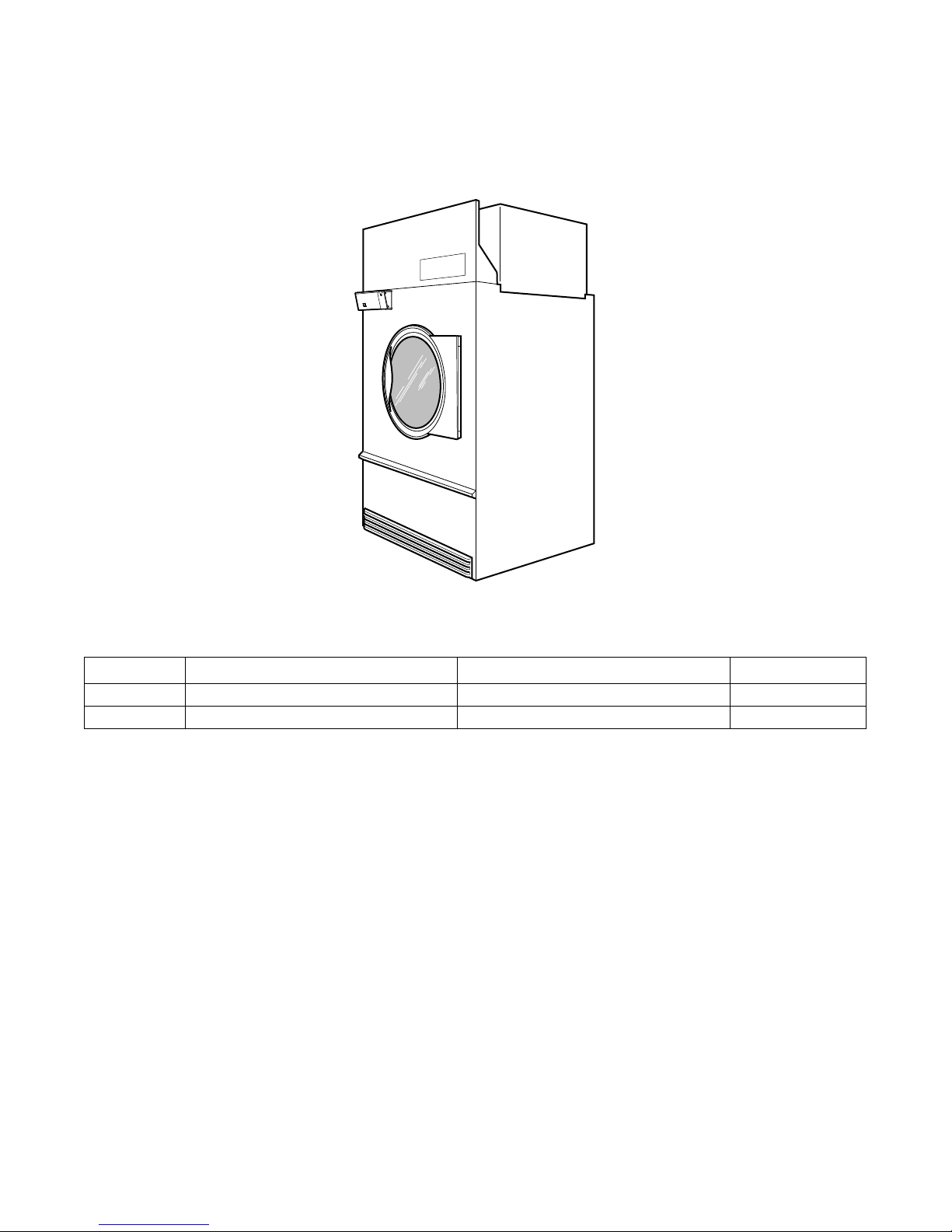
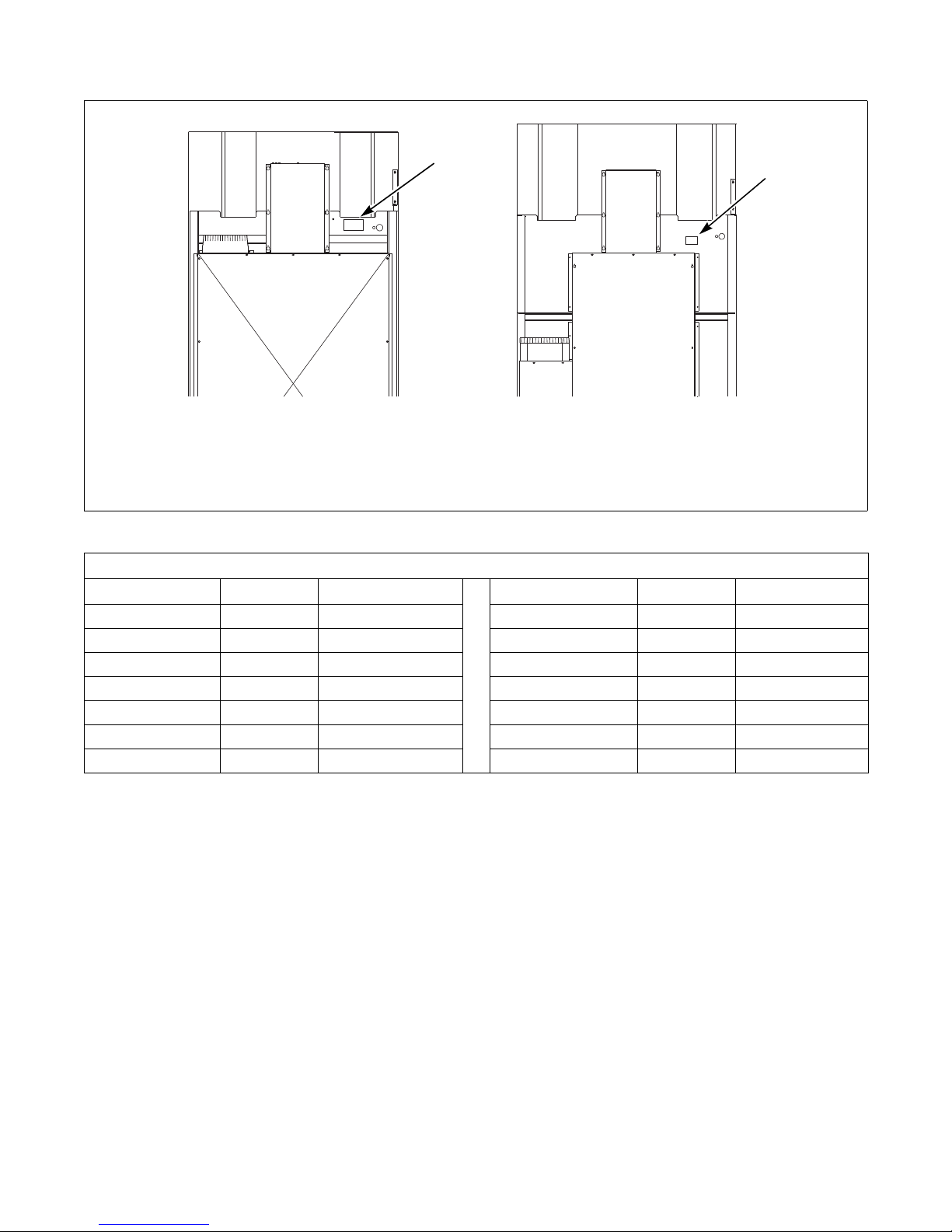
TMB2288N
1Serial Plate
TMB2288N
120 POUND TUMBLER
1
1
170 POUND TUMBLER
Conversion Table
Multiply By To Obtain Multiply By To Obtain
Btu 0.252 kCal Pounds/sq. inch 0.06895 Bars
Btu 1055 Joules Pounds/sq. inch 0.070 kg/sq. cm
Inch 25.4 Millimeters Pounds (lbs.) 0.454 Kilograms
Inches W.C. 0.036 Pounds/sq. inch Boiler Horsepower 33,479 Btu/hr.
Inches W.C. 0.249 kPa Boiler Horsepower 34.5 lbs. steam/hr.
lb./inch2(psi) 6.895 kPa CFM 0.471 liters/second
ft.328.32 Liters kW 3414 Btu/hr.
© Copyright, Alliance Laundry Systems LLC – DO NOT COPY or TRANSMIT
Tumblers – 120 and 170
4
3-09-71
Specifications and Dimensions
Specifications 120 Pound 170 Pound
Noise level measured during operation
at operator position of 3.3 feet (1 meter)
in front of machine and 5.2 feet
(1.6 meters) from floor.
66 dBA 66 dBA
Cylinder Size:
Inches (mm)
44 x 41
(1118 x 1041)
50.75 x 42.5
(1289 x 1080)
Cylinder Capacity dry weight:
Pounds (kg)
120
(54.4)
170
(77.1)
Cylinder Motor Horsepower 0.75 0.75
Fan Motor Horsepower 13
Air Outlet Diameter:
Inches (mm)
10
(254)
12
(300)
Maximum Static Back Pressure:
W.C.I. (mbar)
0.3
(0.8)
0.3
(0.8)
Maximum Airflow:
C.F.M (L/sec.)
1600
(755)
2450
(1156)
Gas Models
Net Weight (approximate):
Pounds (kg)
1275
(580)
1575
(716)
Gas Connection 3/4 in. NPT 1 in. NPT
Gas Burner Rating:
Btu/hr. (Mj/hr.)
270,000
(285)
395,000
(421)
Steam Models
Net Weight (approximate):
Pounds (kg)
1375
(625)
1675
(761)
Steam Connection 3/4 in. NPT inlet
3/4 in. NPT outlet
3/4 in. NPT inlet
1 in. NPT outlet
Steam Coil Rating at 100 psig:
Boiler Horsepower (Btu/hr.)
(recommended operating pressure
80-100 psig)
11.7
(405,000)
18.8
(648,000)
Electric Models
Heating Element Rating:
kilowatts (kW)
60 kW Not Applicable
© Copyright, Alliance Laundry Systems LLC – DO NOT COPY or TRANSMIT
Tumblers – 120 and 170
3-09-71
5
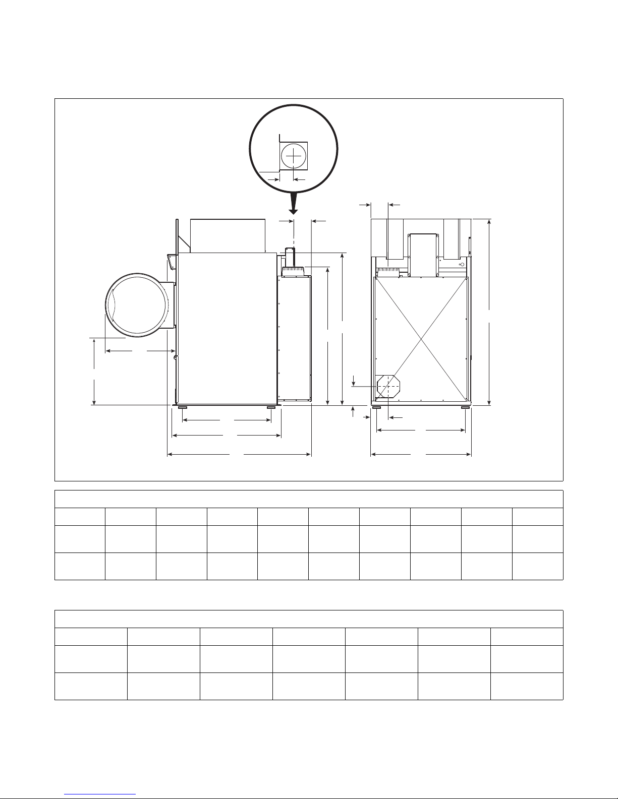
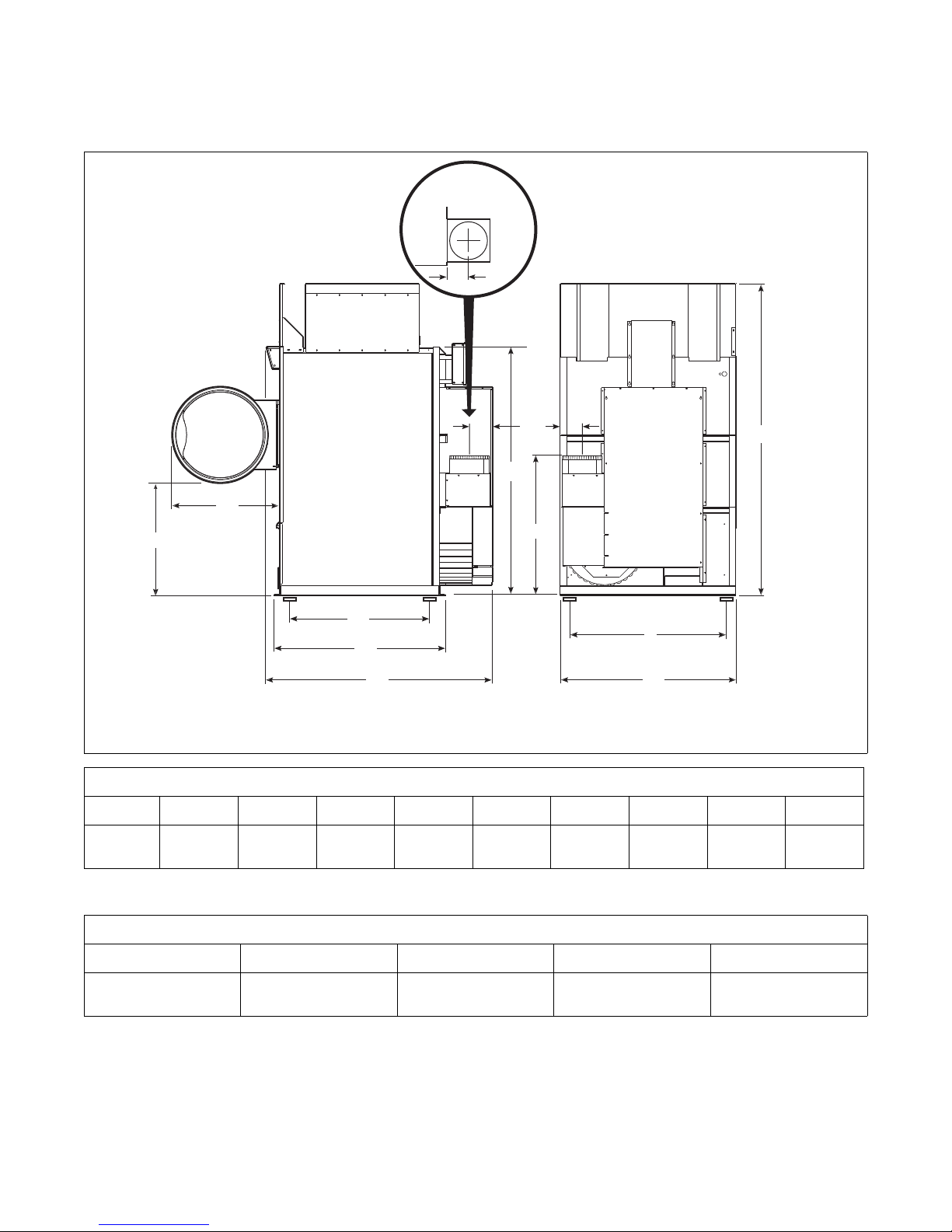
120 Pound Tumbler Dimensions and
Exhaust Outlet Locations
Refer to Position and Level the Tumbler to temporarily reduce the heights of these models.
TMB2326N
TMB2326N
A
B
C
D
U
V
X
H
F
Z
Y
W
TOP VIEW OF
EXHAUST
DUCT
EG
I
Cabinet Dimensions
Models A B C D E F G H I
120L/N/E 31.38 in.
(797 mm)
32.5 in.
(826 mm)
48.91 in.
(1242 mm)
49.91 in.
(1268 mm)
67.92 in.
(1725 mm)
45.38 in.
(1153 mm)
46.38 in.
(1178 mm)
85.7 in.
(2177 mm)
70 in.
(1778 mm)
120S 31.38 in.
(797 mm)
32.5 in.
(826 mm)
48.91 in.
(1242 mm)
49.91 in.
(1268 mm)
67.92 in.
(1725 mm)
45.38 in.
(1153 mm)
46.38 in.
(1178 mm)
83.5 in.
(2121 mm)
70 in.
(1778 mm)
Exhaust Outlet Dimensions and Locations
Models U V W X Y Z
120L/N/E 63.45 in.
(1612 mm)
8.44 in.
(214 mm)
5 in.
(127 mm)
8.18 in.
(208 mm)
6.82 in.
(173 mm)
8.18 in.
(208 mm)
120S 60.7 in.
(1542 mm)
8.44 in.
(214 mm)
5 in.
(127 mm)
8.18 in.
(208 mm)
6.82 in.
(173 mm)
8.18 in.
(208 mm)
© Copyright, Alliance Laundry Systems LLC – DO NOT COPY or TRANSMIT
Tumblers – 120 and 170
6
3-09-71
170 Pound Tumbler Dimensions and
Exhaust Outlet Locations
Refer to Position and Level the Tumbler to temporarily reduce the heights of these models.
TMB2327N
TMB2327N
A
B
C
D
WH
F
Y
X
V
TOP VIEW OF
EXHAUST
DUCT
EG
I
Cabinet Dimensions
ModelsABCDEFGH I
170L/N/S 33.86 in.
(860 mm)
32.5 in.
(826 mm)
50.75 in.
(1289 mm)
51.75 in.
(1314 mm)
68.85 in.
(1749 mm)
52.12 in.
(1324 mm)
53.12 in.
(1349 mm)
94 in.
(2388 mm)
75.12 in.
(1908mm)
Exhaust Outlet Dimensions and Locations
Models V W X Y
170L/N/S 42.38 in.
(1076 mm)
6.75 in.
(171 mm)
6 in.
(152 mm)
7 in.
(178 mm)
© Copyright, Alliance Laundry Systems LLC – DO NOT COPY or TRANSMIT
Tumblers – 120 and 170
3-09-71
7
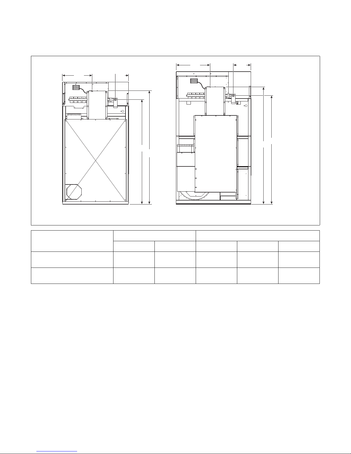
Electric and Gas Connection Locations
for Gas Models
NOTE: These figures are approximate dimensions only.
TMB2255N
AC
C
A
B
D
BD
120L/N 170L/N
Models Electrical Connection Gas Connection
A B C D Diameter
120L/N 18.34 in.
(466 mm)
77.84 in.
(1977 mm)
12.5 in.
(318 mm)
70.5 in.
(1791 mm)
3/4 in. NPT
170L/N 21 in.
(533 mm)
81 in.
(2057 mm)
14.85 in.
(377 mm)
77.4 in.
(1966 mm)
1 in. NPT
© Copyright, Alliance Laundry Systems LLC – DO NOT COPY or TRANSMIT
Tumblers – 120 and 170
8
3-09-71
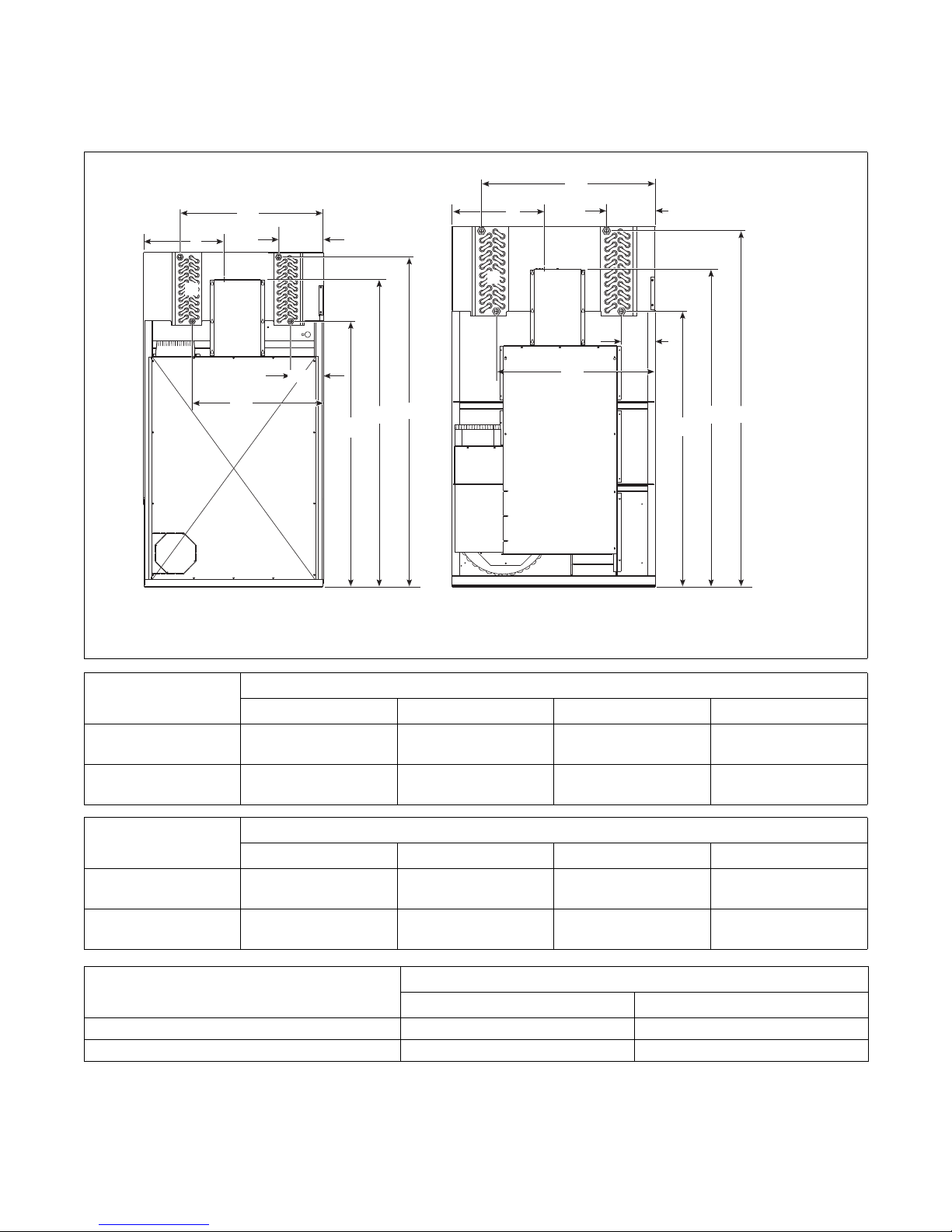
Electric and Steam Connection Locations
for Steam Models
TMB2256N
A1
B1
120S 170S
A2
B2
DEF
A1
B1
B2
A2
D
EF
CC
Models Steam Inlet
Diameter A1 A2 F
120S 3/4 in. NPT 35.875 in.
(911 mm)
13.375 in.
(340 mm)
82.75 in.
(2102 mm)
170S 3/4 in. NPT 37.625 in.
(956 mm)
15.25 in.
(387 mm)
88 in.
(2235 mm)
Models Steam Outlet
Diameter B1 B2 D
120S 3/4 in. NPT 34.625 in.
(879 mm)
13.125 in.
(333 mm)
68.5 in.
(1740 mm)
170S 1 in. NPT 44.625 in.
(1133 mm)
8.75 in.
(222 mm)
71.75 in.
(1822 mm)
Models Electrical Connection
CE
120S 18.34 in. (466 mm) 77.84 in. (1977 mm)
170S 21 in. (533 mm) 81 in. (2057 mm)
© Copyright, Alliance Laundry Systems LLC – DO NOT COPY or TRANSMIT
Tumblers – 120 and 170
3-09-71
9
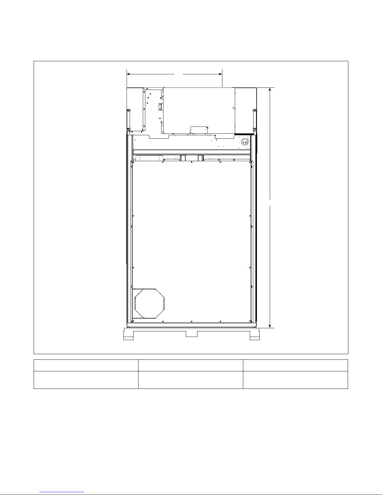
Electric Connection Location for
Electric Models
TMB2336N
A
B
Models A B
120E 35.81 in.
(910 mm)
85.64 in.
(2175 mm)
This manual suits for next models
9
Table of contents
Other IPSO Dryer manuals


Popular Dryer manuals by other brands

Bosch
Bosch WTA79200GB Installation and operating instructions

Amana
Amana W10233410A Use and care guide

Miele
Miele TWH 780 WP operating instructions

Asko
Asko T760 user guide

Alliance Laundry Systems
Alliance Laundry Systems 25 Series Original instructions

Bosch
Bosch Logixx 10 WTB76556GB Instruction manual and installation instructions


Indesit
Indesit IDV 75 instruction manual

Infiniton
Infiniton SD-DG85C manual

BOMANN
BOMANN WT 5019 instruction manual

Alliance Laundry Systems
Alliance Laundry Systems TMB795C Installation

Asko
Asko T793C operating instructions

Kenmore
Kenmore 8041 - 5.8 cu. Ft. Capacity Electric Dryer installation instructions