IPSO HC60 User manual

IPSO - LSG n.v
Nieuwstraat 146 - B-8560 Wevelgem (België)
Tel. 056/41 20 54 - Fax 056/41 86 74
Instruction manual
HC60 HC65 HC75 HC100
HC135 HC165
Technical specifications
Installation instructions
Operating instructions
Maintenance

3
4
4
7
10
10
10
10
10
11
12
13
13
14
15
23
29
30
30
30
31
33
Content
Contents
1 General safety instructions ..........................................................................
2 Technical data and dimensions ...................................................................
Technical data ..................................................................................................
Dimensions.......................................................................................................
3 Installation and connection ..........................................................................
Ground .............................................................................................................
Removal of the transport safety .......................................................................
Water connection .............................................................................................
Water drain.......................................................................................................
Main power connection ....................................................................................
Liquid soap connection.....................................................................................
Connection of a central operating panel for coinmachines (option) .................
Steam connection.............................................................................................
4 Operating instructions .................................................................................
Machine with start button ................................................................................
Machine with coin or token operation...............................................................
5 Standard programs ......................................................................................
6 Technical remarks ........................................................................................
Internal connection of the electrical heating .....................................................
Tilt switch .........................................................................................................
Error messages ................................................................................................
7 Maintenance of the machine ........................................................................
Code: 249/00306/20
11/01/2006
3
1
General safety instructions
Ignoring any of the safety instructions can cause serious
personal injury and can also cause damage to the linen or
the machine
Read the installation and instruction manual carefully before connecting the
machine.
It is recommended that the machine be installed by qualified technicians.
The machine should be installed according to the installation instructions.
(See chapter 3)
The machine should be grounded according to the instructions in order to
eliminate the risk of electrocution.
Do not expose the machine to high humidity or extreme high or low tempe-
ratures.
Cut off all main water inlets, steam and electrical supplies at the end of each
operating day.
Before starting repairs or maintenance, shut off all power and water sup-
plies.
To prevent fire and explosion:
Keep the area around the machine free from inflammable or combustible
products.
Do not put fabrics that are treated with inflammable products into the machine.
These fabrics should be hand-washed or air-dried first.
Always carefully read and follow the instructions on the packing of detergents.
Store these products out of the reach of children.
Always take into account the instructions on the labels of clothes.
Never allow children to play in the surroundings of a machine.
These instructions surely cannot prevent all risks of accidents. It is up to the user to act with the
utmost precaution.
Do not hesitate to contact the dealer in case of a problem.
Remark:

4
Technical data and dimensions
2
Technical data
HC60
Capacity (dry weight)
1/11 5 kg
1/10 5,5 kg
1/9 6,1 kg
Cylinder
Diameter 530 mm
Depth 250 mm
Volume 55 Lit
Cabinet
Height 1005 mm
Width 660 mm
Depth 575 mm
Front loading
Diameter door opening 300 mm
Door height 355 mm
To center 505 mm
Speed
Wash 10 -50 tr/min
Distribution 85 tr/min
Spin 250 - 1250 tr/min
G-force
low spin/High spin 74 - 462
Motor (3-fasig)
4p. 1470 tr./min 550W
Drain valve
Depend-O-Drain 6/4"
Water supply
Hard, soft, warm water 3/4"
Heating
Electrical 230/400V 4,2 kw
Electrical 400V 6 kw
Steam X
Warm water (without additional heating) X
Warm water (with additional heating) X
Packing dimensions
(H x W x D) mm 1140x740x840
Weight
Nett 184 kg
Gross 198 kg

5
Technical data and dimensions
2
Technical data
HC65 HC75 HC100
Capacity (dry weight)
1/11 5,9 kg 6,9 kg 8,6 kg
1/10 6,5 kg 7,6 kg 9,5 kg
1/9 7,2 kg 8,4 kg 10,5 kg
Cylinder
Diameter 530 mm 530 mm 530 mm
Depth 295 mm 345 mm 440 mm
Volume 65 Lit 76 Lit 95 Lit
Cabinet
Height 1038 mm 1038 mm 1038 mm
Width 660 mm 660 mm 660 mm
Depth 739 mm 739 mm 839 mm
Front loading
Diameter door opening 300 mm 300 mm 300 mm
Door height 365 mm 365 mm 365 mm
To center 505 mm 505 mm 505 mm
Speed
Wash 10 - 50 tr/min
Distribution 85 tr/min
Low spin 250 - 500 tr/min
High spin 500 - 1000 tr/min
G-factor
Low spin/high spin 74/ 296
Motoren (3-fasig)
4p. 1470 tr./min 750W
Drain valve
Depend-O-Drain 6/4"
Water supply
Hard, soft, warm water 3/4"
Steam connection
Steam connection 3/8"
Heating
Electrical 230/400 V 4,2/ 6/ 9 kW
Electrical 400V 12 kW
Steam X
Warm water (without additional heating) X
Warm water (with additional heating) X
Packing dimensions
(H x W x D) mm 1140x740x840-1140x740x840-1250x740x950
Weight
Nett 207 kg 211 kg 236 kg
Gross 229 Kg 233 kg 258 kg

6
HC135 HC165
Capacity (dry weight)
1/11 12 kg 15 kg
1/10 13,2 kg 16,5 kg
1/9 14,5 kg 18,3 kg
Cylinder
Diameter 650 mm 650 mm
Depth 400 mm 500 mm
Volume 132 Lit 165 Lit
Cabinet
Height 1202 mm 1202 mm
Width 780 mm 780 mm
Depth 842 mm 942 mm
Front loading
Diameter door opening 300 mm 300 mm
Door height 475 mm 475 mm
To center 605 mm 605 mm
Speed
Wash 10 - 50 tr/min
Distribution 85 tr/min
Low spin 250 - 500 tr/min
High spin 500 - 1000 tr/min
G-factor
Low spin/high spin 88/ 363
Motoren (3-fasig)
4p. 1470 tr./min 1500W
Drain valve
Depend-O-Drain 6/4"
Water supply
Hard, soft, warm water 3/4"
Steam connection
Steam connection 3/8"
Heating
Electrical 230/400 V 12/15/18 kW
Electrical 400V 21/24 kW
Steam X
Warm water (without additional heating) X
Warm water (with additional heating) X
Packing dimensions
(H x W x D) mm 1310x 850x 940 mm - 1310x 850x 1080 mm
Weight
Nett 325 kg 358 kg
Brutt 355 Kg 388 kg
Technical data and dimensions
2
Technical data
7
660
530
1011
365
1038
33 33
65 65 485
565
62269
30 30
163
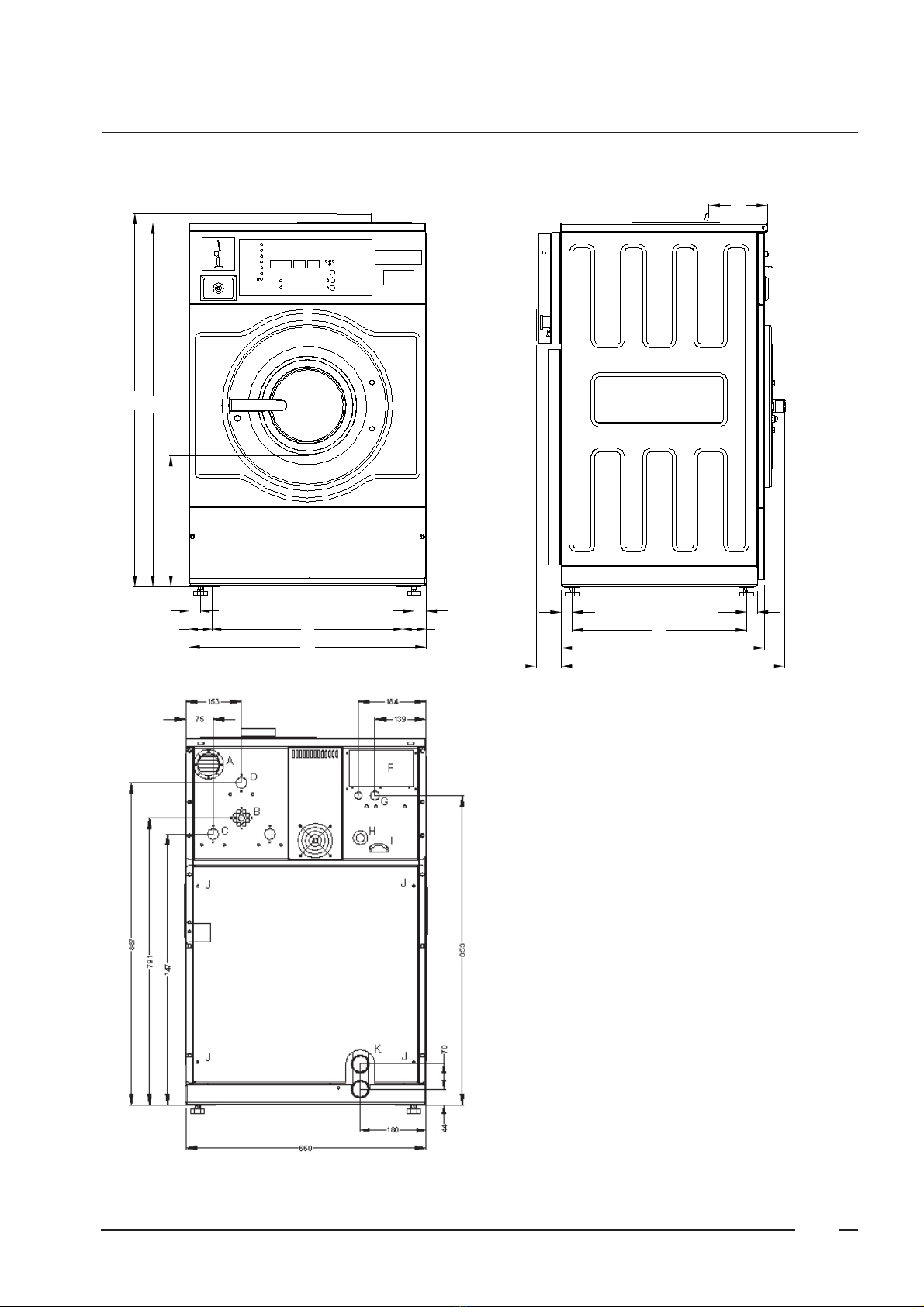
A. Ventilation soap dispenser
B. Liquid soap connetions
C. Hard water connections 3/4"
D. Warm water connections 3/4"
F. Connections clamps
G.Electrical connections
H.Emergency button
I. Ventilation tub
J. Bolt pattern for fixation of the machine
K. Drain valve
L. Steam connections
Dimensions
2
HC60

8
660
530
1011
365
1038
33 33
65 65
HC65/75 = 727 - HC100 = 827
HC65/75 = 670 - HC100 = 770
HC65/75 = 590 - HC100 = 690
69
30 30
220
660
485
747
791
887
231
75
C
L
B
E
A
153
D
853
180
44
K
139
184
I
H
G
F
70
A. Ventilation soap dispenser
B. Liquid soap connetions
C. Hard water connections 3/4"
D. Warm water connections 3/4"
E. Soft water connections 3/4"
F. Connections clamps
G.Electrical connections
H.Emergency button
I. Ventilation tub
K. Drain valve
L. Steam connections
Dimensions
2
HC65 - 75 - 100

9
1202
1175
66
780
64866
34 34
475
HC135 = 816 - HC165 = 916
HC135 = 760 - HC165 = 860
HC135 = 665 - HC165 = 765
82
36.5
88
36.5
220
530
893
935
968
267
202
105
L
B
D
C
332
A
E
1008
60
200
K
200
155
I
H
G
F
35
70
Dimensions
2
HC135 - 165
A. Ventilation soap dispenser
B. Liquid soap connetions
C. Hard water connections 3/4"
D. Warm water connections 3/4"
E. Soft water connections 3/4"
F. Connections clamps
G.Electrical connections
H.Emergency button
I. Ventilation tub
K. Drain valve
L. Steam connections

10
A
AA
A
The machine (with rubber feet) must be placed on a flat, solid bottom (concrete
or fixed ground). When using a metal socle or with machines with steam heating,
the machine (without feet) must be anchored on the foreseeing points (A) in
the base (bolts M10). (see Dimensions 2).
The machine must be placed entirely level. For easy maintenance it is recom-
mended to keep a minimal distance of 600 mm between the wall and the back
of the machine.
If several machines are placed next to each another, there should be a minimal
distance of 30 mm between each machine.
To prevent damage during transportation, the machine has been
equipped with two red transport brackets (A) to eliminate every
possible movement of the tub.
After the machine has been placed level, take off the backpannel
and remove these transport brackets.
Important
The machine must never be activated before removing
these transport brackets.
Removal of the transport safety
The machine is delivered with hoses with 3/4" connections. These hoses fit the
water inlet valves of the machine and the main water inlet taps. To ensure the
optimal functioning of the water inlet valves, the water pressure on the inlet
should be between 0,5 and 10 kg/cm² (7 and 145 psi). If the pressure is too
low, the cycle time will increase considerably.
In case of boiler fed machines, a minimum of hot water of 90°C should
be available: HC60: 46l. HC65: 55 l. HC75: 65 l. HC100: 80l.
HC135: 100l. H165: 120l.
Water connection
Water drain The machine is equipped with a drain valve with 6/4" outer diameter (50 mm).
This drain valve should be connected to the drain by means of the drain elbow
which is delivered with the machine.
The diameter of the main drain should be adapted to the water flow and the
number of machines. It should be sufficient to handle at least 80L/min. per
machine.
It is necessary to connect the main drain at least on one side to an open air-
brake to allow ventilation.
Important
The bolt pattern for the fixation of the HC60 machine is foreseen in the
back panel of the cabinet. Put this panel on the floor and indicate the
holes (see page 7).
Installation and connection
3
Ground
This manual suits for next models
5
Table of contents
Other IPSO Washer manuals


Popular Washer manuals by other brands

Tricity Bendix
Tricity Bendix AW 1000 W Operating & installation instructions

Panasonic
Panasonic NA-F60L5WRB operating instructions

GE
GE WSLP1500 Dimensions and installation information

Electrolux
Electrolux EWF1284EDW Service manual

Bosch
Bosch WAN2829BSN User manual and installation instructions

LG
LG TV2516DV3B owner's manual


