IPSO HF150 User manual

IPSO - LSG n.v.
Nieuwstraat 146 - B-8560 Wevelgem (België)
Tel. 056/41 20 54 - Fax 056/41 86 74
HF150 HF185
HF234
Instruction manual
Technical specifications
Installation instructions
Operating instructions
Maintenance
Part No. D0289

3
4
4
6
8
8
8
8
9
9
10
11
12
13
13
21
27
28
28
28
29
31
Content
Contents
1 General safety instructions ..........................................................................
2 Technical data and dimensions ...................................................................
Technical data ..................................................................................................
Dimensions .......................................................................................................
3 Installation and connection ..........................................................................
Ground .............................................................................................................
Removal of the transport safety .......................................................................
Water connection .............................................................................................
Water drain .......................................................................................................
Main power connection ....................................................................................
Liquid soap connection .....................................................................................
Connection of a central operating panel for coinmachines (option) .................
Steam connection .............................................................................................
4 Operating instructions .................................................................................
Machine with start button ................................................................................
Machine with coin or token operation ...............................................................
5 Standard programs ......................................................................................
6 Technical remarks ........................................................................................
Internal connection of the electrical heating .....................................................
Tilt switch .........................................................................................................
Error messages ................................................................................................
7 Maintenance of the machine ........................................................................
Code: 249/00324/20
19/12/2005

1
General safety instructions
Ignoring any of the safety instructions can cause serious
personal injury and can also cause damage to the linen or
the machine
❐
❐
❐
❐
❐
❐
❐
❐
❐
❐
❐
Read the installation and instruction manual carefully before connecting the
machine.
It is recommended that the machine be installed by qualified technicians.
The machine should be installed according to the installation instructions.
(See chapter 3)
The machine should be grounded according to the instructions in order to
eliminate the risk of electrocution.
Do not expose the machine to high humidity or extreme high or low tempe-
ratures.
Cut off all main water inlets, steam and electrical supplies at the end of each
operating day.
Before starting repairs or maintenance, shut off all power and water sup-
plies.
To prevent fire and explosion:
Keep the area around the machine free from inflammable or combustible
products.
Do not put fabrics that are treated with inflammable products into the ma-
chine. These fabrics should be hand-washed or air-dried first.
Always carefully read and follow the instructions on the packing of deter-
gents. Store these products out of the reach of children.
Always take into account the instructions on the labels of clothes.
Never allow children to play in the surroundings of a machine.
JThese instructions surely cannot prevent all risks of accidents. It is up to the user to act with the
utmost precaution.
JDo not hesitate to contact the dealer in case of a problem.
Remark:

Technical data and dimensions
2
Technical data
HF150 HF185
Capacity (dry weight)
1/11 13 kg 16,4 kg
1/10 14,5 kg 18 kg
1/9 16 kg 20 kg
Cylinder
Diameter 680 mm 680 mm
Depth 400 mm 500 mm
Volume 145 Lit 181 Lit
Cabinet
Height 1348 mm 1348 mm
Width 780 mm 780 mm
Depth 840 mm 940 mm
Front loading
Diameter door opening 395 mm 395 mm
Door height 565 mm 565 mm
To center 770 mm 770 mm
Speed
Wash 10 - 50 tr/min
Distribution 85 tr/min
Low spin 250 - 500 tr/min
High spin 500 - 1000 tr/min
G-factor
Low spin/high spin 94 / 380
Motoren (3-fasig)
4p. 1470 tr./min 2200W
Drain valve
Depend-O-Drain 2"
Water supply
Hard, soft, warm water 3/4"
Steam connection
Steam connection 3/8"
Heating
Electrical 230/400 V 12/15/18 kW
Electrical 400V 21/24 kW
Steam 6 bar
Warm water (without additional heating) X
Warm water (with additional heating) X
Packing dimensions
(H x W x D) mm 1495x850x930 - 1495x850x1030
Weight
Nett 424 kg 454 kg
Gross 440 Kg 470 kg

HF234
Capacity (dry weight)
1/11 21,3 kg
1/10 23,4 kg
1/9 26 kg
Cylinder
Diameter 750 mm
Depth 530 mm
Volume 234 Lit
Cabinet
Height 1505 mm
Width 900 mm
Depth 985 mm
Front loading
Diameter door opening 395 mm
Door height 630 mm
To center 820 mm
Speed
Wash 10 - 50 tr/min
Distribution 100 tr/min
Low spin 250 - 500 tr/min
High spin 500 - 1000 tr/min
G-factor
Low spin/high spin 74/ 373
Motoren (3-fasig)
4p. 1470 tr./min 3000W
Drain valve
Depend-O-Drain 3"
Water supply
Hard, soft, warm water 3/4"
Steam connection
Steam connection 3/8"
Heating
Electrical 230/400 V 12/15/18 kW
Electrical 400V 24 kW
Steam 6 bar
Warm water (without additional heating) X
Warm water (with additional heating) X
Packing dimensions
(H x W x D) mm 1650x 1020x 1150 mm
Weight
Nett 570 kg
Brutt 630 kg
Technical data and dimensions
2
Technical data

1375.5
1348
780
565
68050 50
86.5
88 220
HF150 = 733 - HF185 = 833
HF150 = 665 - HF185 = 76534 34
HF150 = 753 - HF185 = 853
1181.5
1066.5
935
1141.5
703.5
L
K
185
170
332
267
202
105
D
C
B
A
200
155
H
E
I
G
F
35
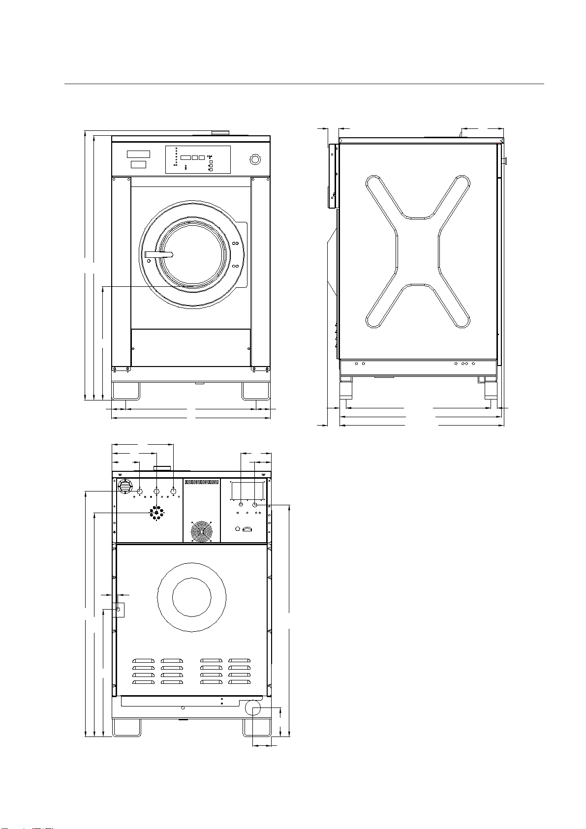
JA. Ventilation soap dispenser
JB. Liquid soap connetions
JC. Hard water connections 3/4"
JD. Warm water connections 3/4"
JE. Soft water connections 3/4"
JF. Connections clamps
JG.Electrical connections
JH.Emergency button
JI. Ventilation tub
JK. Drain valve
JL. Steam connections
Dimensions
2
HF150 - 185
720
35
1265.5
1386
155.5
251
346
94
173
165
105
1309.5
F
L
K
A
C
B
DE
G
I
1500
738
900
81 81
1527.5
645
HF234 = 939.5
HF234 = 926
HF234 = 830
70
35
60
35
240
H
Dimensions
2
HF234
JA. Ventilation soap dispenser
JB. Liquid soap connetions
JC. Hard water connections 3/4"
JD. Warm water connections 3/4"
JE. Soft water connections 3/4"
JF. Connections clamps
JG.Electrical connections
JH.Emergency button
JI. Ventilation tub
JK. Drain valve
JL. Steam connections

HF234
HF150-185
The machine must be placed on a flat, solid surface (metal base, concrete
or solid ground). It is recommended that the machine be anchored on the
provided places (A) in the base, especially in case of a plinth
(see Dimensions 2).
The machine must be placed entirely level. For easy maintenance it is re-
commended to keep a minimal distance of 600 mm between the wall and
the back of the machine.
If several machines are placed next to each another, there should be a mi-
nimal distance of 30 mm between each machine.
To prevent damage during transportation, the machine has been equipped
with four red transport brackets to eliminate every possible movement of
the tub.
After the machine has been placed level, take off the service- and the back
panel to remove these transport brackets.
Important
The machine must never be activated before removing
these transport brackets.
Removal of the transport safety
The machine is delivered with hoses with 3/4" connections. These hoses
fit the water inlet valves of the machine and the main water inlet taps. To
ensure the optimal functioning of the water inlet valves, the water pres-
sure on the inlet should be between 0,5 and 10 kg/cm² (7 and 145 psi). If
the pressure is too low, the cycle time will increase considerably.
In case of boiler fed machines, a minimum of hot water of 90°C should be
available: For the HF150: 94 l. HF185: 115 l. HF234: 150 l.
Water connection
Installation and connection
3
Ground

3
JRemove the cover plate at the back of the machine. (See dimen-
sions (E)).
JConnect the power cable to the connectors.
220V 3AC
220V 3 phase (3AC) should be connected to the connectors
“L1,L2,L3”.
The green/yellow grounding clamp has to be connected to the
grounding wire “PE”.
380 V 3AC + N
380 V 3 phase (3AC + N) has to be connected to the connectors
“L1,L2,L3”, the blue neutral to the “N” connector.
The green/yellow grounding clamp has to be connected to the
grounding wire “PE”.
JAfter connection, check the spin direction. The cylinder must
spin in the direction of the arrow, showed on the sticker on the
door window (clockwise).
JA wrong spin direction can damage the motor, and can also
cause water to spurt from the soap dispenser.
Electrical Connection
The machine is equipped with a drain valve (HF150-185) with 2" ou-
ter diameter (50mm) (HF234) 3" outer diameter (80 mm). This drain
valve should be connected to the drain by means of the drain elbow
which is delivered with the machine.
JThe diameter of the main drain should be adapted to the water
flow and the number of machines. It should be sufficient to handle
at least 160L/min. per machine.
JIt is necessary to connect the main drain at least on one side to
an open air-brake to allow ventilation.
JWhen the main drain has not been sufficiently deodorized, eve-
ry machine should be installed seperately with a deodorizer.
Water drain
machine with steam heating or boiler fed machines without ad-
ditional electrical heating
Power of the breaker plugs:
220V 3AC 380V 3AC + N
9kw 25A 16A
12 kW 40 A 20 A
15 kW 50 A 25 A
18 kW 50 A 32 A
21 kW ---- 40 A
24 kW ---- 40 A
machine with electrical heating
220V 3AC 380V 3AC + N
16 A 16 A
3
With an external tension 24V DC
Electrical connection of the
liquid soap pumps
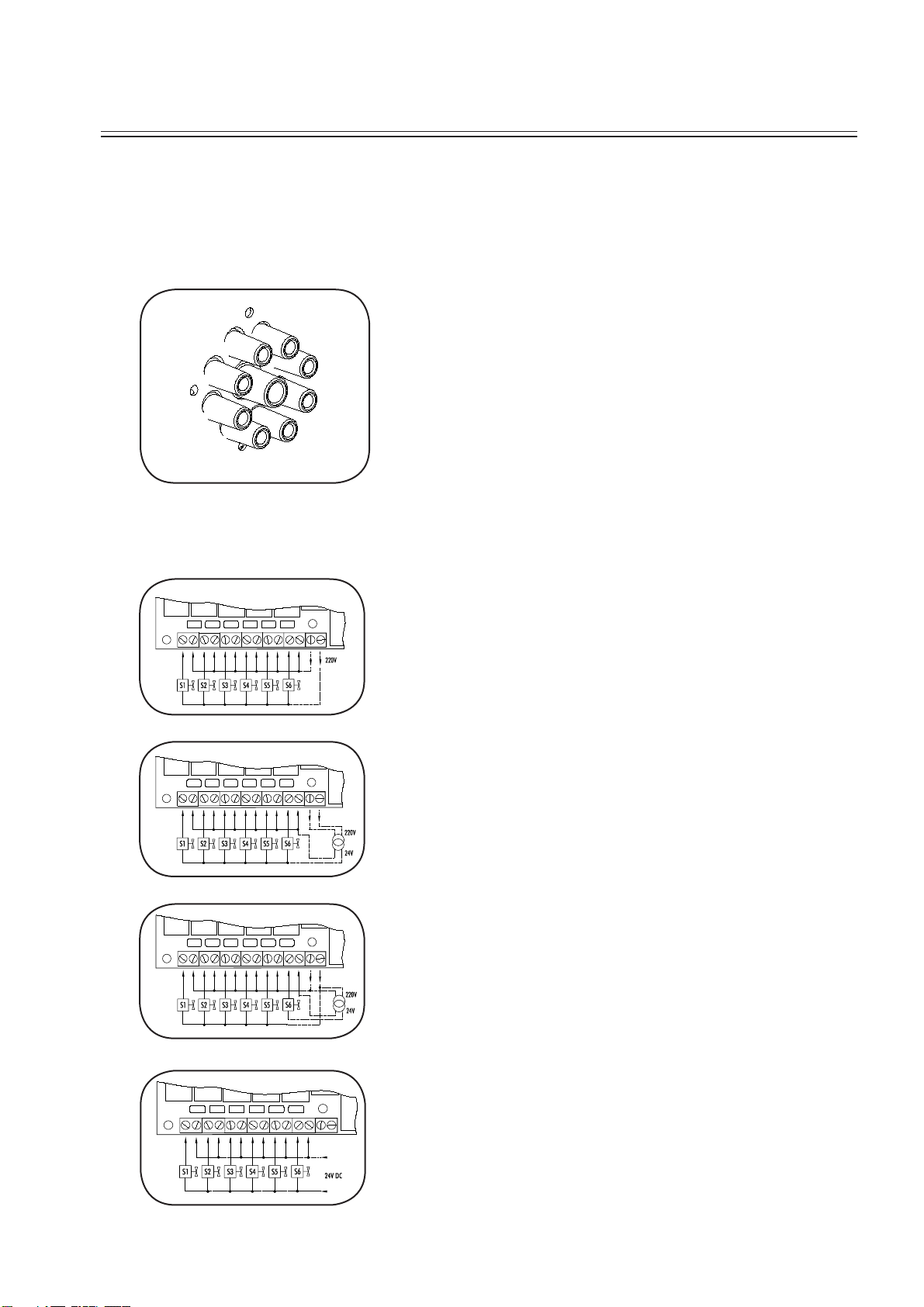
On machines equipped with a liquid soap connection, connect the
wires directly on the print board next to the ground wire connec-
tion (option). Connect as indicated on the wiring diagram.
The two connectors on the right give a tension of 220V ~ (max.
4A) which can be applied to drive 220V ~ soap pumps. If more
than 4A is required, an external tension will have to be used. 6
connections have been provided, of which one (S6) can be used to
drive a waterproofing pump (e.g. for rain coats, etc.).
The 220V can be transformed to other values to drive other type
soap pumps.
Example: pumps 24V ~.
Also, pumps with different operating tension can be combined.
Example: 5 pumps 220V ~ and 1 pump 24V ~.
The liquid soap connection consists of 8 connections for liquid soap
(SI….S).
The central opening is used for ventilation.
Liquid soap connection (option)
Connection of the liquid soap
hoses
This manual suits for next models
2
Table of contents
Other IPSO Washer manuals


Popular Washer manuals by other brands

Tricity Bendix
Tricity Bendix AW 1000 W Operating & installation instructions

Panasonic
Panasonic NA-F60L5WRB operating instructions

GE
GE WSLP1500 Dimensions and installation information

Electrolux
Electrolux EWF1284EDW Service manual

Bosch
Bosch WAN2829BSN User manual and installation instructions

LG
LG TV2516DV3B owner's manual


