Electrical specifications (typical values unless otherwise stated)
Power supply (VDD) 3.2 V to 5.5 V DC
Internal supply voltage (VCC) 3 V
upply current (when peripherals inactive) 650 µA
Temperature range 0 °C to +70 °C
Dimensions 48 mm x 27 mm x 11 mm
Weight 10 g
Absolute maximum ratings
tresses above those values may cause permanent damage to the device. Exposure to maximum rating conditions for
extended periods may affect device reliability.
upply voltage: 6.0 V
torage temperature: -40 °C to +85 °C
Hardware
Power supply
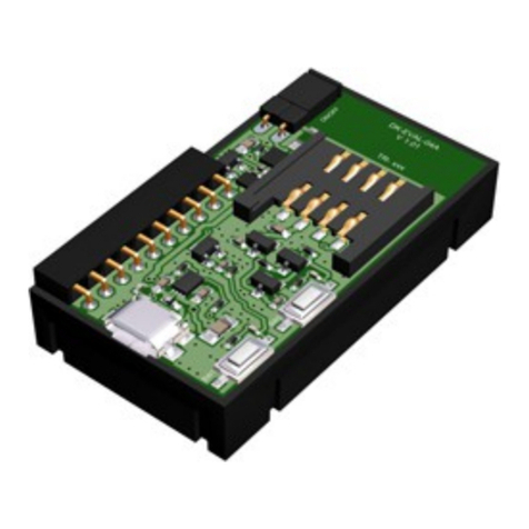
DDC- E-01 should be supplied from DK-EVAL-04 via connector XC2.
Interface connectors
The XC2 male connector with square 0.635 mm, 2.54 mm pitch pins
is intended for I/Os and power supply.
Corresponding XC1 female connector serves for interconnection with
other DDC kits.
XC3 is a 1.25 mm pitch miniature connector DF13C-5P (Hirose).
Mating Hirose cable connector: DF13-5 (plastic shell), DF13 crimp
contacts.
Internal peripherals
•I2C temperature sensor: MCP9802A3 (Microchip) with fixed I2C
slave address 10010110 (in binary).
•1-wire temperature sensor: D 1820B20 (Dallas).
•Photoresistor: PGM5539 by Token. Resistance 30-90 kΩ at 10
lux, dark resistance 5 MΩ.
•Potentiometer: The potentiometer is intended for voltage
measurement using the A/D converter inside the MCU on the TR
transceiver.
Caution
To enable correct functionality of the pushbutton W1 on the DK-EVAL-04(A) kit connected, the potentiometer shaft
must be in the intermediate position.
E ternal I2C peripheral
•External I2C device should be connected via the XC3 connector. It must have I2C slave address different from 10010110
(in binary).
Jumper JP1
•In position 1 – 2 enables 1-wire sensor.
•In position 2 – 3 enables I2C temperature sensor and I2C external bus.
Refer to datasheets of used devices.
Software
Ready-to-use examples are available in the tartup package at www.iqrf.org.
© 2018 IQRF Tech s.r.o. www.iqrf.org User_Guide_DDC- E-01_180918 Page 3


