IREM EX-170 G/3-US User manual

Film-Tech
The information contained in this Adobe Acrobat pdf
file is provided at your own risk and good judgment.
These manuals are designed to facilitate the
exchange of information related to cinema
projection and film handling, with no warranties nor
obligations from the authors, for qualified field
service engineers.
If you are not a qualified technician, please make no
adjustments to anything you may read about in these
Adobe manual downloads.
www.film-tech.com

Electronic power supply
INSTALLATION AND OPERATION MANUAL
MAN0094/2


3
MAN0094/2
GENERAL PURPOSES Description.............................................................................................. 5
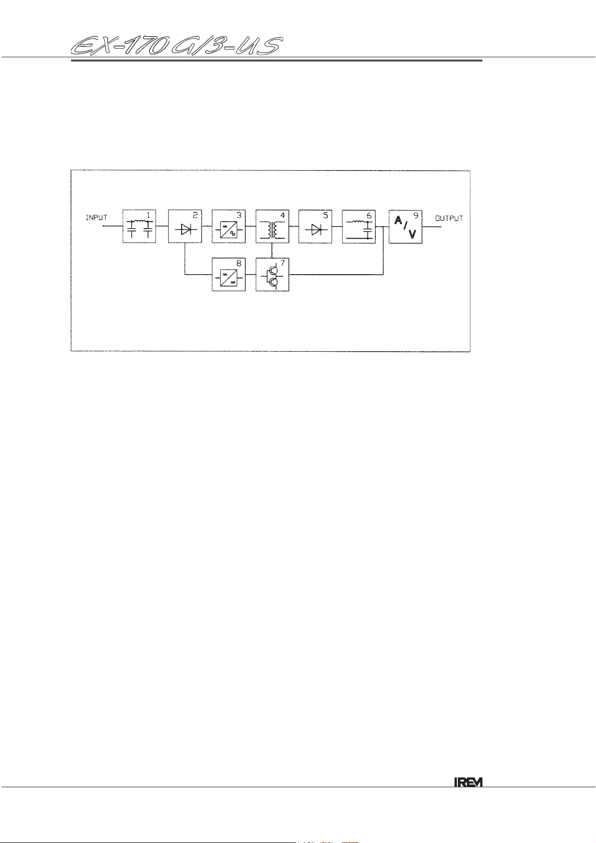
Block diagram ......................................................................................... 6
TECHNICAL SPECIFICATIONS
Technical specifications* ........................................................................
7
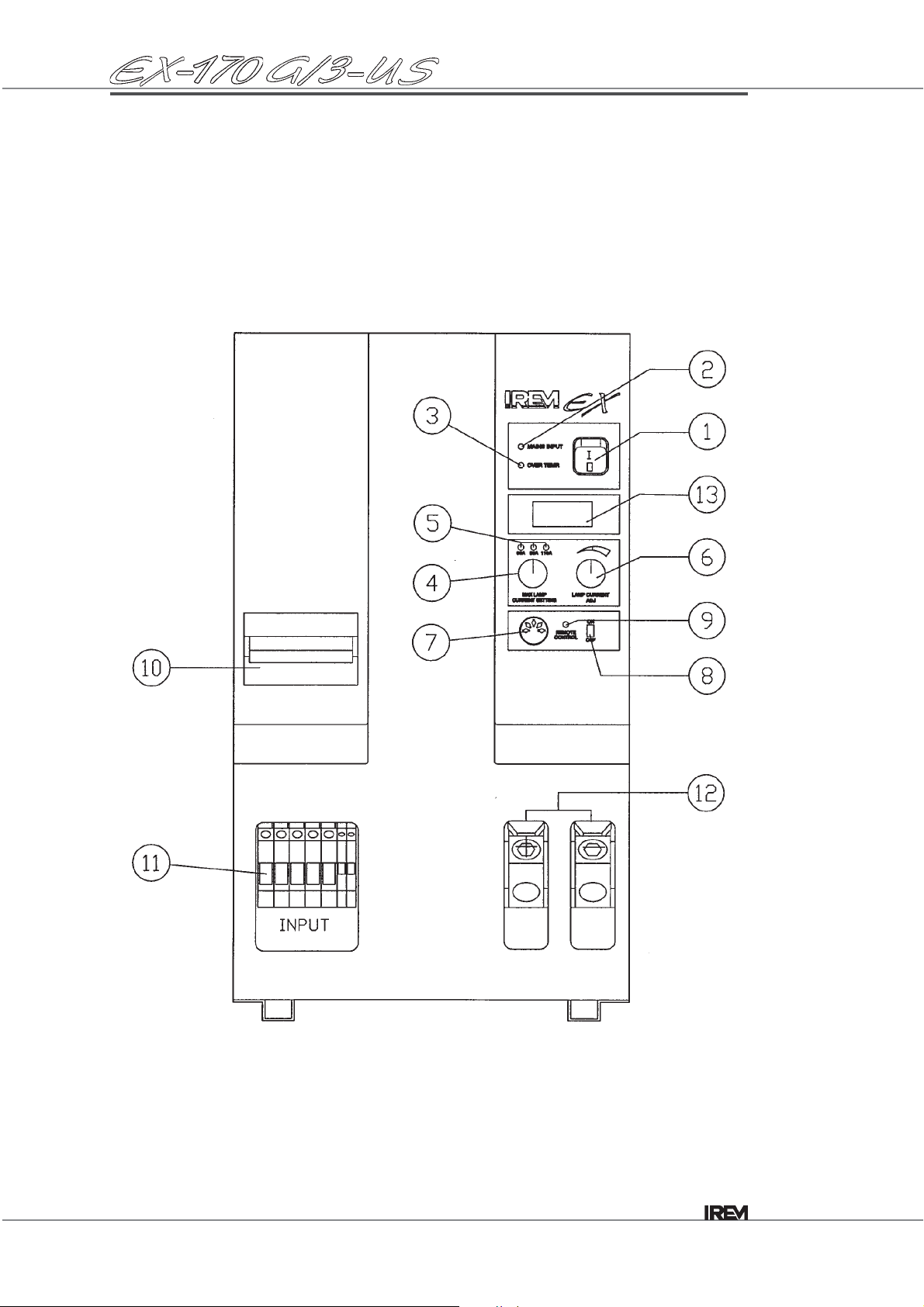
FUNCTIONS AND CONTROLS Control devices ....................................................................................... 8
CONNECTION AND OPERATING INFORMATION
Receiving the unit ................................................................................... 10
Delivery arrangement ............................................................................. 10
Storage ................................................................................................... 10
Removing of package and handling ....................................................... 10
Installantion - environment...................................................................... 10
Warnings................................................................................................. 11
Feet mounting displacement................................................................... 11
Preliminary checks.................................................................................. 12
Preparing the cables for remote control operation.................................. 12
Connecting the input-output cables ........................................................ 13
Connecting the cable for remote control operation................................. 13
DIRECTIONS FOR USE Local operation through the front panel controls .................................... 14
Switching on ........................................................................................... 14
Changing the lamp current ..................................................................... 14
Switching off ........................................................................................... 15
Remote operation ................................................................................... 16
Switching on ........................................................................................... 16
Setting the lamp current.......................................................................... 17
Changing the lamp current ..................................................................... 18
Switching off ........................................................................................... 18
Overheating protection and alarms......................................................... 19
Fan replacement..................................................................................... 20
TROUBLESHOOTING Possible failures...................................................................................... 21
TECHNICAL DATA Suggested wiring diagram ...................................................................... 24
Overall dimensions*................................................................................
25
* these sections have been modified with respect to the previous issue.
Table of contents

MAN0094/2 4
Caution !
You should read this manual before attempting any intervention inside the unit.
Thenoncompliancewiththeinstructionsgiveninthismanualcanleadtoserious
damage to the unit which in this case will invalidate the warranty.
Nocompensationor indemnityunderanykindwillbeacknowledgedforinjury or
damageduetouseormisuseoftheproduct,forpooroperationoftheappliances
connected to IREM product or for immediate or indirect damage caused to the
powered equipment.
During the warranty period the replacement of defective parts and maintenance
procedures will be exclusively carried out at IREM servicing centre.
Keep this manual along with the unit.
CE declaration is available on request.
Thismanualaimstogivesomeoperatinginstructionstotheuserinordertograntasafe
and optimal use of the unit.
Keep this manual along with the unit. You should read it carefully both for installation,
starting-up and maintenance procedures.
This manual is composed by the following sections:
. description
(product and application fields)
.functions and controls
(main characteristics and operation modes)
.connection and operating information
(directions for connection, start-up and use of the power supply)
.technical characteristics

5
MAN0094/2
Description
This electronic power supply for three phase 208VAC - 50/60Hz input, has been
designed to feed from 2000 to 7000W short arc Xenon lamps, meeting all the
requirements of lamp manufacturers to ensure correct operation, long life to the lamp,
and high reliability.
Thiscompactandlightweightpowersupplyhas beendesignedtomeettherequirements
of a unit to be installed inside a cabinet.
Its particularly compact design, the advanced circuitry and the displacement of input
and output terminal board and the lamp current adjustment make the unit suitable to a
wide variety of applications both in vertical and horizontal position and specifically:
-standard film projection
-theatre applications
-architectural applications
-solar simulations.

MAN0094/2 6
1. Input filter board
Limiting the high frequency interferences (complying with EMI/EEC Standards).
2. Diode bridge rectifier
Converting the alternated voltage from the mains into direct voltage
3. Inverter board
Designed in compliance with IGBT technology, H type full bridge configuration
4. High frequency transformer
Granting the galvanic insulation between input and output
5. Output rectifier circuit
Composed by two fast low noise diodes
6. Output filter
Granting the lamp ripple current value at <1% pk- pk.
7. Driving board
Driving and controlling the unit
8. Auxiliary powering board
9. Digital instrumentation
Displaying output voltage and current values
Block diagram

7
MAN0094/2
Technical specifications
Lamp capacity 2000W to 7000W
Nominal input voltage range 187-230V 3ph +N
Input frequency 47-63Hz
Insulation class CL1
Rated current (max.) 25A
Sinusoidal absorption not provided
DC output current 60-170A
DC max. voltage 47.5V
No-load voltage 140V
No-load voltage rising time 3 s
Ripple <1%
Efficiency 0.9
Output overload protection electronic
Lamp striking soft-start ignition current
Ventilation forced
Remote ON/OFF switching external switch
Igniter insertion control not provided
Lamp current remote setting 0÷10V control
Setting of lamp current limit provided
Output current stabilisation provided
Input circuit breaker provided
Input extra voltage protection provided
Lamp ON signalisation provided
Display signals mains ON
max. temperature
ON/OFF remote control
lamp max. current setting
digital ammeter to read output current
digital voltmeter to read output voltage
Safety standards EN 61204
EMC standards EN 50081-2 EN 50082-2 EN 50082-1
IEC 61000-6-2 IEC 61000-6-4
Markings CE, UL (for US market)
Operating temperature 0°C to 45°C
Storage temperature -20°C to +60°C
Protection degree IP00
Dimensions 255x475x420h mm
Weight 33 kg

MAN0094/2 8
Functions and controls
Control devices

9
MAN0094/2
1. ON/OFF switch
2. Mains input LED
3. Overtemperature LED
Lit in case of overheating
4. Lamp current selector
Permittingtoselectthemax.poweringcurrentinaccordancetothelampcapacity
5. Current LED
Highlighting the selected current range.
6. Lamp current potentiometer
Adjusting the lamp output current
7. Remote control connector
Connecting the remote control cable
8. Remote control selector
Selecting the ON/OFF switching and the lamp current directly on the unit or
remotely by means of the remote control device (0÷10V).
9. Remote control LED
Lit when the unit is on remote operation
10. Input circuit breaker
11. Input terminal board
12. Output terminal board
13. Digital instrumentation
Displaying lamp current and voltage values
Functions and controls
Control devices
Table of contents
Other IREM Power Supply manuals
Popular Power Supply manuals by other brands

Videx
Videx 520MR Installation instruction

Poppstar
Poppstar 1008821 Instructions for use

TDK-Lambda
TDK-Lambda LZS-A1000-3 Installation, operation and maintenance manual

TDK-Lambda
TDK-Lambda 500A instruction manual

Calira
Calira EVS 17/07-DS/IU operating instructions

Monacor
Monacor PS-12CCD instruction manual


