IriSys SafeCount User manual

Installation Guide

Version 4 | February 2021Page 2
1EQUIPMENT REQUIRED
2YOUR SAFECOUNT SENSOR
3SYSTEM OVERVIEW
4PRIMARY SENSOR INSTALLATION
5SECONDARY SENSOR INSTALLATION
6SYSTEM CONFIGURATION
7UNDERSTANDING DEVICE LEDs
8DISCLAIMER
INSTALLATION GUIDE

Version 4 | February 2021Page 3
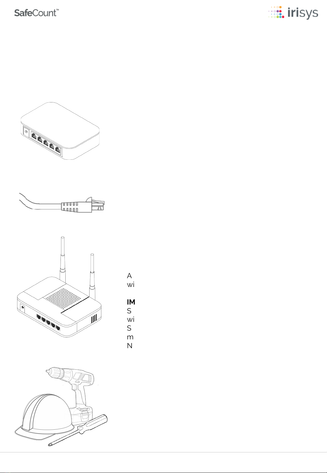
You will also require suitable tools to mount each
SafeCount Sensor and personal protective
equipment (PPE), especially when working at height.
SUITABLE TOOLS & PPE
A WiFi Router is recommended and should have a
wired connection to your PoE Switch.
IMPORTANT -Without a WiFi Router, the SafeCount
Sensors will not be assigned (DHCP) IP addresses and
will revert to a default IP Address of 192.168.0.10. Each
Sensor will need to be configured (in turn) with a unique
manual IP address. We recommend contacting your
Network Administrator for guidance on how to
configure manually.
WIFI ROUTER (RECOMMENDED)
Your SafeCount Primary Sensor should be connected
to a PoE Switch on your network via CAT 6 Ethernet
•Cables with a maximum length of 100m / 328 ft.
•CAT5 Cables can be used, however we recommend
CAT6 or better, with gauge AWG 22 or 23.
CAT5/6 ETHERNET CABLES
The SafeCount Primary Sensor and/or SafeCount
Secondary Sensor requires a Power over Ethernet
(PoE) Switch in order for the SafeCount Sensor to be
powered
PoE SWITCH
The following equipment is required for acomplete system, most of which will already
be present in atypical setup.
1EQUIPMENT REQUIRED

Version 4 | February 2021Page 4
The base plate has a number of
screw holes for complete flexibility
when fixing to the ceiling
There is a white plastic clip at the
top of the base plate, which allows
the SafeCount Sensor to be
separated from it when required
*The SafeCount Sensor weighs approx.550g (19.4oz), so always use appropriate fixings
to secure the base plate in place.
550g (19.4oz)
(Weight)*
32mm (1.25in)
(Depth)
110mm (4.33in)
(Width)
195mm (7.68in)
(Length)
Your SafeCount Sensor is the most important part of your new counting solution, so it is
important to familiarize yourself with the Sensor and its key component parts.
YOUR SAFECOUNT SENSOR
2

Version 4 | February 2021Page 5
Factory Reset Button
Network Cable Connection
USB Type A Host Connection
(for use with SafeCount Display Kits)
Micro USB Type B Device Connection
(reserved for future use)
SD Card Slot
(do not remove)
Mounting Lugs
Mounting Lugs
Please familiarize yourself with the underside of your SafeCount Sensor and the key
component parts that can be found there.
YOUR SAFECOUNT SENSOR
2

Version 4 | February 2021Page 6
CAT 5/6 CABLE
YOUR EXISITING NETWORK
SafeCount Secondary Sensors
Installed at Secondary Entrances (Up to maximum of 20)
SafeCount Primary Sensor
Installed at Primary Entrance
Before starting your installation, it is important to understand how your new SafeCount
Sensor -as well as any SafeCount Secondary Sensors you may have - are connected
with your own equipment, to form acomplete system.
SYSTEM OVERVIEW
3
If your SafeCount system does not include a WiFi Router, please follow the
instructions on the following page to manually set each SafeCount sensors IP
address.

Version 4 | February 2021Page 7
CAT 5/6 CABLE
SafeCount Secondary Sensors
Installed at Secondary Entrances (Up to maximum of 20)
SafeCount Primary Sensor
Installed at Primary Entrance
If your setup does not include aWiFi Router, then your SafeCount Sensors will not be
assigned (DHCP) IP addresses and will each revert to adefault IP Address of 192.168.0.10.
Each Sensor will need to be configured (in turn) with aunique manual IP address.We
recommend contacting your Network Administrator for guidance on how to configure
manually.
You should plug each Sensor in one-by-one when configuring their IP addresses, as
having multiple devices with the same IP address on the network can lead to unforeseen
issues.We would further recommend setting these unique addresses prior to installing
on the ceiling, but it is equally possible to do so after the Sensors have been ceiling
mounted, provided only one Sensor is powered and configured at atime.
Your SafeCount Sensors should be configured in line with your own network architecture
needs and if required, you should consult your IT department or network administrator
for how best to configure the devices to match your corporate network needs.
3SYSTEM OVERVIEW

ADoorway Width (Maximum)
BCeiling or Installation Height
Doorway
Width
A
Mounting
Height B
Your SafeCount Primary Sensor should be installed at the main entrance (and exit) of
your designated building.
We recommend that you measure and record the maximum width of your chosen
doorway as well as the ceiling height in front of the doorway, so that you can more
accurately position your SafeCount Primary Sensor.Your measurements will be needed
to determine the optimum mounting location.
4PRIMARY SENSOR INSTALLATION
Version 4 | February 2021Page 8

Version 4 | February 2021Page 9
Doorway
Distance From
Doorway
C
Place the Base Plate on to the ceiling, the correct distance back from the doorway.The
‘Distance from Doorway’ measurement (C)is the total distance from the door to the
bottom of the Base Plate.The arrow on the Base Plate should point into the building
and away from the door, with aclear view to the floor.
A
Doorway Width
B
Minimum Mounting Height*
C
Distance From Doorway
Up to 195cm (76in) 250cm (98in) 45-59cm (18-23in)
196-230cm (77-90in) 275cm (108in) 51-72cm (20-28in)
231-265cm (91-104in) 300cm (118in) 64-84cm (25-33in)
266-335cm (105-132in) 350cm (138in) 76-110cm (30-43in)
336-410cm (133-161in) 400cm (157in) 89-135cm (35-53in)
*The minimum mounting height is 250cm and Sensors should never be installed below this height.
The maximum mounting height of any SafeCount Sensor should never exceed 450cm (177in)
To ensure that the Base Plate of your SafeCount Primary Sensor is ceiling mounted, the
correct distance back from your chosen doorway, you should use the quick reference
table below in-conjunction with your Aand Bmeasurements, to determine C.
4PRIMARY SENSOR INSTALLATION

Version 4 | February 2021Page 10
Distance from
Doorway
C
If the ceiling height at the correct distance from doorway ( C) is greater than the
maximum recommend Sensor mounting height of 450cm (177in), then a suitable
mounting pole should be used.
4PRIMARY SENSOR INSTALLATION

Version 4 | February 2021Page 11
As your SafeCount Primary Sensor weighs approx.550g (19.4oz), we would
always recommend that you use appropriate fixings to secure the base plate in
place.
Take care not to distort the base by over tightening fixings, especially if using an
electric screwdriver.
Ensure that your SafeCount Primary Sensor is mounted level, with the lenses
pointing straight down.
4PRIMARY SENSOR INSTALLATION

Version 4 | February 2021Page 12
Once you have installed the Base Plate, you will need to cut a hole in the ceiling for
cable access. The Sensor body is larger than the Base Plate so locate the area marked
below and feed your ethernet cable through ready for connection.
4PRIMARY SENSOR INSTALLATION

Version 4 | February 2021Page 13
You are now ready to connect the Ethernet Cable to the Network Cable Connection
Socket on the SafeCount Primary Sensor and then slide the Sensor onto the base plate.
Ensure that the plastic clip on the Base Plate clicks into place when the Sensor is fitted..
4PRIMARY SENSOR INSTALLATION

Version 4 | February 2021Page 14
If the LEDs do not illuminate double check your connections and ensure that
your PoE switch is powered up correctly.
For more information regarding the LED indicators please refer to ‘Section 7–
Understanding Device LEDs’.
LED INDICATORS
Your SafeCount Primary Sensor should now power up, This is indicated by the two LEDs
on the front of the device showing RED initially then flashing various sequences.
4PRIMARY SENSOR INSTALLATION

Version 4 | February 2021Page 15
CAT 5/6 CABLE
SafeCount Secondary Sensors
Installed at Secondary Entrances (Up to maximum of 20)
SafeCount Primary Sensor
Installed at Primary Entrance
If you have multiple entrances/exits and wish to cover these with SafeCount Secondary
Sensors, then simply follow the same instructions as for the SafeCount Primary Sensor
above (Section 4)and ensure that the SafeCount Secondary Sensors are connected to
the same PoE switch and (WiFi) Router on your network.
5SECONDARY SENSOR INSTALLATION

Version 4 | February 2021Page 16
Once you have installed all the SafeCount Sensors that you require, you will need to run
through the simple configuration wizard in order complete the setup.
CONNECTION VIA (WIFI) ROUTER
•Connect your laptop/mobile device to your WiFi router (wired or wireless)
•Locate the SafeCount Sensor serial number on the box (or back of SafeCount sensor)
•Use your web browser (we recommend Google Chrome) to navigate to the address
below:
http://yourserialnumber.local/safecount/
e.g. http://V4D-20200133.local/safecount/
•ALOGIN FORM will appear
•To proceed you will need to enter the following credentials:
USERNAME:admin
PASSWORD:installer
•Follow the on-screen instructions
6SYSTEM CONFIGURATION

Version 4 | February 2021Page 17
If you do not have a WiFi Router then you will need to follow the steps below using a
physical (wired) connection to the PoE Switch instead.
CONNECTION NOT VIA (WIFI) ROUTER
•Connect your laptop/computer to the same PoE Switch as your SafeCount Sensor(s)
•Each SafeCount Sensor ships with a default IP address of 192.168.0.10, so you will
need to ensure that you have set a manual IP Address for your laptop/computer in
the same range as the SafeCount Sensor address in order to connect
•Use your web browser (we recommend Google Chrome) to navigate to the address
below:
http://192.168.0.10/safecount/
•ALOGIN FORM will appear
•To proceed you will need to enter the following credentials:
USERNAME:admin
PASSWORD:installer
•Follow the on-screen instructions
6SYSTEM CONFIGURATION

Version 4 | February 2021Page 18
CHANGE SETTINGS
Should you wish to manually
assign an IP address to your
SafeCount Sensor you can do so
by selecting this option. If selected
an additional Network Setup
screen will appear allowing you to
configure as required.
KEEP SETTINGS
An IP address will automatically be
assigned to your SafeCount Sensor
if you have a DHCP server (router)
on your network. We recommend
keeping this dynamic address.
Selecting this option will take you
to the next section of the Setup
Wizard
Once you have successfully logged in to the SafeCount System for the first time the
Setup Wizard will automatically guide you through the basic configuration steps.
SETUP WIZARD –NETWORK SETUP
You will initially be asked about the Network Settings that your SafeCount Sensor will
be using when connected to your network.
6SYSTEM CONFIGURATION

Version 4 | February 2021Page 19
CANCEL CONFIGURATION
Selecting this option will take you
back to the previous screen with an
automatically assigned (DHCP) IP
address
SAVE SETTINGS
You will need to click on the
Complete Network Setup option
to save your manual configuration.
Doing so will enable you to move
to the rest of the setup wizard
MANUAL SETTINGS
Here you can manually assign the
IP address, subnet mask and
Gateway IP address as well as
manually setting any domain name
server (DNS) addresses.
DISABLE DHCP
In order to be able to edit the
network settings manually, you will
first need to de-select (untick) the
default (recommended) option
The network settings will remain
greyed out until this option is de-
selected.
If you opt to manually assign an IP address to your SafeCount Sensor then abasic
knowledge of network configuration.Is assumed
SETUP WIZARD –NETWORK SETUP –MANUAL CONFIGURATION
Here you can manually configure the IP address and associated network settings.
6SYSTEM CONFIGURATION

Version 4 | February 2021Page 20
SAVE & CONTINUE
For each step of the Setup Wizard
you will need to select the Next
button which will save any changes
you make and progress you to the
next setting
LOCATION NAME
Here you should enter a name for
the location where the SafeCount
Sensor has been installed. This
might typically be a company
name and geographical location
i.e. FIRST RETAIL -OXFORD
With the Network Setup complete you will be taken to the next stage of the Setup
Wizard as detailed below.
SETUP WIZARD –SITE DETAILS
Here you will be asked to complete information specific to the location of the SafeCount
Sensor(s) being installed.
6SYSTEM CONFIGURATION
Table of contents