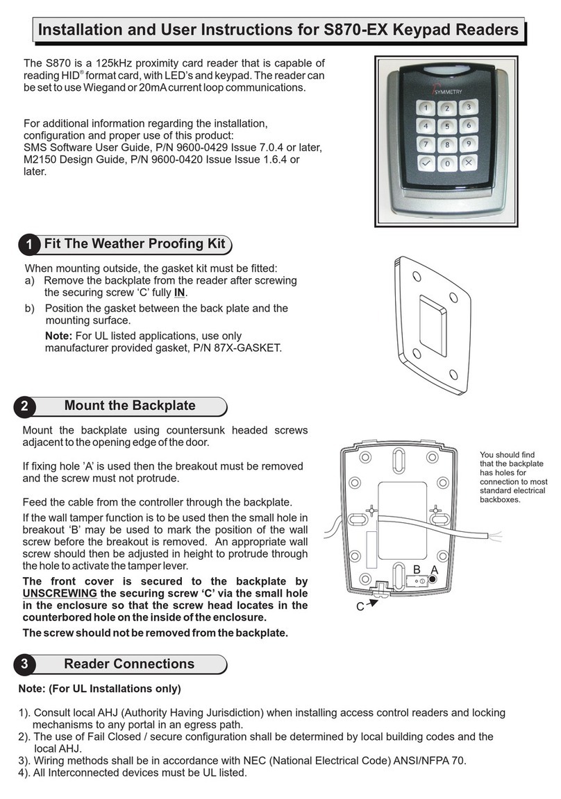
Iron logic Matrix-IV EHT Keys Metal User manual

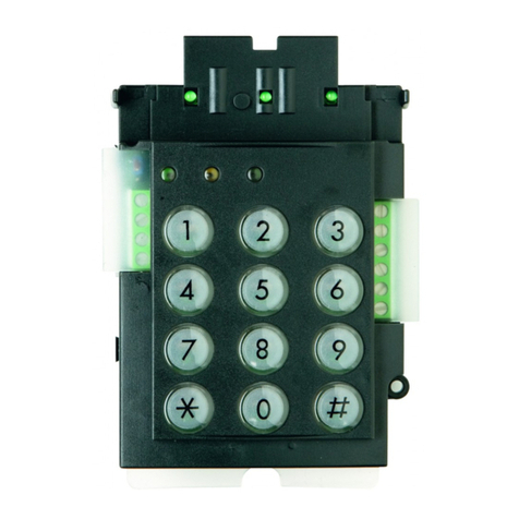
Matrix-IV EHT Keys Metal Reader
User Manual
1. OVERVIEW
Matrix-IV EHT Keys Metal Reader is used in ACS (Access Control Systems). The reader
transfers EM-Marine, HID (Prox Card II) or Atmel 5557 (Temic) token codes into controller, or
allows for entering the codes on its keypad. The codes are transferred via iButton™ (Dallas
Touch Memory) or Wiegand-26/Wiegand-42 protocols.
The reader can distinguish the original contactless ID cards from their cloned copies. This
allows to disable transferring the ID codes (numbers) of cloned cards into controller (Anti-clone
Mode).
2. MOUNTING AND CONNECTION
The reader should be mounted on a flat surface, at a place where proximity cards can directly
approach the reader (see Fig. 1).
<Figure 1. Dimensions and mounting holes>
To mount the reader, perform the following steps:
- Unscrew the screw at the bottom of the case and remove the back lid.
- Apply the back lid to the wall, to mark mounting holes locations.
- Drill the holes.
- Screw the back lid to the wall.
- Mount the reader and attach it with the screw at the case bottom.
- Connect the wires as per Table 1.
- To select the protocol for data transfer to controller, connect DATA0 and DATA1 wires as per
Fig. 2.
- Insulate all the wires junctions.
- Power on the reader and verify its proper operation by touching it with a card.
Notes:
1.Do not install the readers within 10 cm from one another.
2.To work at specified line distance to controller, please use a UTP cable (e.g. a CAT5e cable):
- When connecting via iButton, one wire of a twisted pair connects to GND and another to
DATA0 terminals.
- When connecting via Wiegand, first twisted pair connects to GND and DATA0, and the second
to GND and DATA1 (See Fig. 2).
Matrix-IV EHT Keys Metal www.ironlogic.me
page 1
120 mm
20 mm
2
3
5
7
9
4
6
8
0
ENT
1
ESC
58 mm
Figure 2. Choosing the transmission protocol.
Figure 1. Device Dimensions.
DATA1
GND
D0DATA0
D1
GND
D0iButton
D1
GND
D0iButton
D1
iButton™ (One-time transmission)
Wiegand
iButton™ (DS1990A emulation)
ACS controller
Reader
GND
GND
GND

page 2
Wire colour Wire Purpose
Red +12 V
Black GND - Common
Green DАТ А0
White DАТ А1
Orange LED -G - G reen LED external
control
Brown LED -R - Amber LED external
control
Yellow BEEP - Buzzer external control
Blue SYNC – Reader synchronisation
Pink BELL – Output to external rin ger
Table 1. Connection to controller.
3. OPERATION
Using Proximity cards or key fobs:
When a token is entering the reader working zone, its token ID is acquired. If successful, it is
acknowledged by a short green LED blink and a buzzer signal. While the card stays within working
zone, the white LED shines and keypad backlighting is on. The acquired code is transferred to the
controller in iButton™ (Dallas Touch Memory) or Wiegand-26/Wiegand-42 format, depending on
the chosen transmission protocol settings.
Anti-Clone function:
The main feature of this reader is protection ability against cloned cards. When a cloned card with a
copied card number is presented to the reader, it is recognised as cloned; this allows to prevent
entry using cloned cards if necessary.
To activate Anti-Clone function, refer to Table 2, Reader settings.
Using reader keypad:
The keypad enables to enter the identification code manually. The valid keys for code entry are the
decimal digits 0…9. The pressed keys codes are stored in the reader input buffer, and only are
actually transferred into controller when ENT key is pressed.
Each key press is accompanied with a short buzz. When entering the code from keypad, blue LED
is blinking.
If within 20 s no keys were pressed, the input buffer is cleared, the reader issues a long signal, the
red LED comes on and the reader goes back into standby mode. If one of the digits was entered
incorrectly, press ESC key to clear input buffer and enter the correct digits again.
The allowed code length depends on the chosen output interface protocol:
- For Wiegand-26 and 3-byte iButton™ 1…6 digits;
- For Wiegand-42 and 5-byte iButton™ 1…10 digits.
Note: to choose the output interface protocol, please refer to Table 2.
When the BELL key is pressed, within the reader the BELL output is connected to GND (common).
The external ringer must be connected to the Red (+12V) wire by its positive terminal, and to the
Pink (BELL) wire by its negative terminal.
Matrix-IV EHT Keys Metal www.ironlogic.me

Internal indication:
The visual indication on the reader comprises four LEDs: red, green, blue and white, and audial
indication is done through a built-in buzzer.
The blue LED comes up after powering up the reader and keeps blinking for 3…5 sec. Then red
LED comes up the reader is now in stand-by for card mode. White LED indicates that a card is
found within working zone. Blue LED is blinking while entering a code from the keypad. A short
blink of the green LED and one buzzer signal indicate successful card code reading.
External indication:
The reader allows for external indication control for red and green LEDs and the built-in buzzer.
External indication is performed by controller by shorting the corresponding indication control
input to common wire (-). The variants of external indication control can be found in Table 2.
External indication control can work alongside internal indication control, so that only channel(s)
where an external control signal was received at least once, would switch to external control (and
the rest will stay under internal control).
Synchronisation:
When two readers are installed too close (closer than 20 cm from one another), the
synchronisation feature must be used. Connect blue wires (SYNC) on the readers for that. This
will ensure that the readers operate correctly even under interference.
page 3
Table 2. Configuration codes
Digit No. Parameter
value
Function description Factory
default
1 0 or 1 Active level for external red LED control 0
2 0 or 1 Active level for external green LED control 0
3 0 or 1 Active level for external buzzer control 0
4 0, 1, 2, 3 0: ENT transmits all entered digits (Card emulation)
1: Each keypress transmits 8 bits (hid-09: inverse and straight key
code)
2: Each keypress transmits 4 bits (hid-00: straight key code)
3: Each keypress transmits 6 bits (hid-11: straight key code + 2
parity bits)
0
5 0 or 1 Anti-clone Mode: 0 – OFF, 1 – ON 0
6 0 or 1 0: 3-byte iButton™, Wiegand-26 compatible
1: 5-byte iButton™
1
7 0 or 1 0: Wiegand-26, 1: Wiegand-42 0
8 0, 1, 2, 3 0: Connection protocol: according to Figure 2
1: Connection protocol: Wiegand
2: Connection protocol: iButton™
3: Connection protocol: iButton™ (one-time transfer)
0
9 0 or 1 Keys buffer iButton™ transmission, 1st byte: 0 – 0x01, 1 – 0x03. 0
Matrix-IV EHT Keys Metal www.ironlogic.me

4. CONFIGURATION
This procedure is used to change parameters if the user so wishes, and to restore factory defaults.
The setup procedure requires to change all 9 parameters, the partial change is not supported.
Hence, please define all parameter values before starting the parameters change procedure. If a
parameter purpose is unclear, we recommend to keep its default value.
Entering configuration mode:
1) Power off the reader.
2) Press and hold down the ENT key on the keypad.
3) With the ENT key still pressed, power on the reader. The blue LED will blink.
4) After 15 s the reader produces a sound and turn on the green LED.
5) Release the ENT key and the reader will enter configuration mode. The blue and red LED .
will start to blink alternately. The reader is now ready to configure the parameters, as per Table 2.
(If within 15 s the configuration will not begin, all the parameters will be restored to
factory defaults.)
6) Enter the digits on the reader's keypad. The delay between digits must not exceed 15 s. If an
invalid digit for this parameter is entered, triple signal will sound; you can continue entering the
digits after that.
7) After the last, 9th digit is entered, the reader issues five signals followed by one long signal while
the green LED comes on. The parameters new values are saved and the reader leaves
configuration mode.
8) If a delay between the digits exceeds 15 s, the reader issues ten signals while the red LED
comes on, and leaves the configuration mode, discarding all parameters changes.
Restoring factory defaults:
If no keys were pressed within 15 s after configuration mode has started, the reader restores the
factory defaults and reverts to normal operation. The green LED will come on and a long signal will
sound.
5. SPECIFICATIONS
Working frequency: ...................................................................................125 kHz
Supported token types: .......EM-Marine, HID (ProxCard II) and Atmel 5557 (Temic)
Minimum reading distance:
- ..................................................For EM-Marine, Atmel 5557 (Temic): 5 cm
- ..............................................................................HID (ProxCard II): 3 cm
Output interfaces: . iButton™ (Dallas Touch Memory), Wiegand-26 or Wiegand-42.
Maximum line distance to controller by protocol:
- ..........................................................................................iButton™: 15 m
- .........................................................................................Wiegand: 100 m
Power supply voltage: ..............................................................................12 V DC.
Consumption current: .........................................................................max 150 mA
Maximum Ringer output (BELL) current: ........................................................1.3 A
Operation mode indication: ........................................................Audial and Visual.
External indication control: .........................................................Audial and Visual.
Casing materials: ..........................................................................Silumin, Plastic.
Dimensions, mm: ..............................................................................120 x 58 x 20.
Weight: .........................................................................................................500 g.
page 4
Matrix-IV EHT Keys Metal www.ironlogic.me

6. PACKAGE CONTENTS
-Matrix-IV EHT Keys Metal Reader: ........1
-User Manual: ............................................1
7. OPERATING CONDITIONS
Ambient temperature: -30…40°C.
Humidity: ≤ 98% at 25°C.
When operating under non-recommended conditions, device parameters can deviate from
specified values.
The reader must be operated in absence of: precipitation, direct sunlight, sand, dust, and moisture
condensation.
8. LIMITED WARRANTY.
This Device is covered by limited warranty for 12 months since thepurchase date, but no later
than 18 months from the manufacture date.
The warranty becomes void, if:
- this Manual's guidelines are not followed;
- the device has suffered physical damage;
- the device has visible traces of exposure to moist and/or aggressive chemicals;
- the device circuits have visible traces of tampering by unauthorised parties.
Under this warranty, the Manufacturer shall repair the device or replace any broken parts as
required, free of charge, in cases where the fault is caused by a Manufacturer's defect.
The planned service time for this device: 6 years.
9. TRANSPORTATION AND STORAGE.
The packaged device can be transported in any covered vehicle at the temperatures within
−50…50°C range, while protected from atmospheric precipitation, direct sunlight and
mechanical damage, and transported according to general safety rules for this transportation
mode according to GOST 23088-80 industry standard of Russian Federation.
The device must be stored under Group L conditions according to GOST 15150-69 industry
standard of Russian Federation: ambient temperatures within 5…40 °C, humidity up to 98%.
The maximum storage time for this device is 5 years.
page 5
Matrix-IV EHT Keys Metal www.ironlogic.me

10. CONTACTS
Authorized representative in the European Union:
ICONTROL SIA
Slokas iela 79A, LV-1007, Riga, Latvia
E-mail: info@icontrol.lv
Phone: +37124422922
www.ironlogic.me
page 6
The symbol of crossed-throught waste bin on wheels means that the product
must be disposed of at f separate collection point. This also applies to the product
and all accessories marked with this symbol. Products labeled as such must not
be disposed of with normal household waste, but should be taken to a collection
point for recycling electrical and electronic equipment. Recycling helps to reduce
the consumption of raw materials, thus protecting the environment.
Matrix-IV EHT Keys Metal www.ironlogic.me
Table of contents
