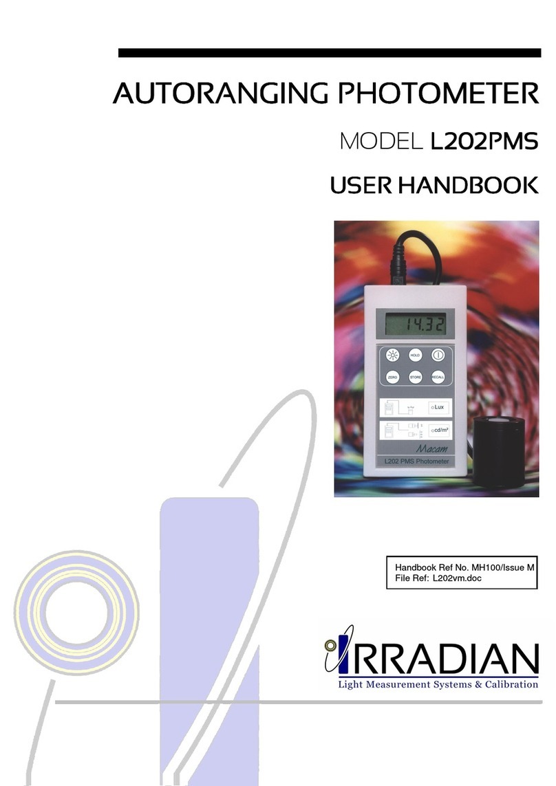
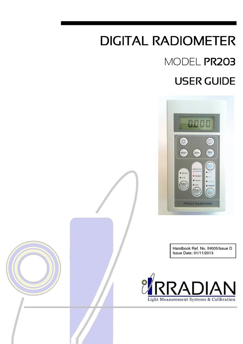
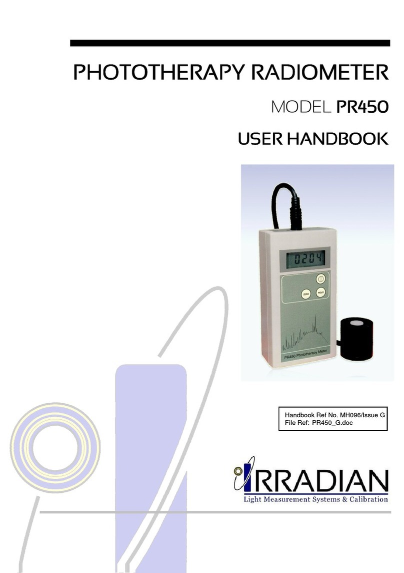
Irradian UV203 Instruction Manual

Handbook Ref No. MH064/Issue K
File Ref: UV203V5K.doc


1. Introduction
2. Specification
3. Operation
4. Irradiance Measurements
5. Cosine Angular Response
6. Calibration Description
7. Care and Maintenance
8. Optional Accessories
9. Block Diagram
10. Programming via the RS232 interface
11. Environmental care, recycling and disposal


UV203 Radiometer Irradian Limited
1
The Irradian portable digital UV radiometer model UV203 is a versatile
direct reading instrument designed specifically for measuring UV
irradiance. It is supplied with a GaAsP solid state detector and a choice
of up to three screw in filters to enable measurements to be made across
the ultra-violet spectrum.
This instrument is especially useful for monitoring the ultra-violet
emissions from high and low pressure mercury vapour lamps, metal
halide lamps and ultra violet fluorescent lamps. Other applications
include the measurements of germicidal lamps used for sterilization,
PUVA lamps used in phototherapy or monitoring industrial ultra-violet
lamps used in the curing of inks & adhesives.
Listed below are some of the standard models available:
MODEL
UV203: UV203 with detector and three filter rings
DET203UV Detector /amplifier
UVA-Cos
UVB2-Cos
IF-254
UV203 A: UV203 with detector and filter ring
DET203UV Detector /amplifier
UVA-Cos
UV203 B: UV203 with detector and filter ring
DET203UV Detector /amplifier
UVB2-Cos
UV203 AB: UV203 with detector and filter ring
DET203UV Detector /amplifier
UVAB-Cos
UV203-254: UV203 with detector and filter ring
DET203UV Detector /amplifier
IF-254
UV203 A+B UV203 with detector and two filter rings
DET203UV Detector /amplifier
UVA-Cos
UVB2-Cos
Irradian Limited UV203 Radiometer
2
DISPLAY UNIT UV203
Controller: 80C51 8bit micro-processor with a 3.1684MHz
clock.
Memory On board non volatile RAM for calibration
factors and set-up parameters.
Key Operation 7 switch key board with 11 LED indicators.
Power Switch Microprocessor reset at switch on.
Unit settings stored prior to shut down.
Serial Interface Three wire RS232 serial interface.
4800 baud, no parity, 1 stop bit.
Integration Time 0.33s
Conversion Scale 17 bit
Accuracy: Measurement accuracy ±1digit with a
linearity error of <1%.
Display: 4½ digit lcd display. Character height 10mm.
Power Supply: 9 volt PP3 battery.
Power Consumption: Shut down mode <5µA
Operating 10 - 20mA
Battery Life ~ 50 hours.

Irradian Limited UV203 Radiometer
3
(continued):
Ranges: Each of the filter rings have up to six ranges according to
the table below:
Note the UV203A,UV203B, UV203-254 and UV203AB
are supplied with only one filter ring.
Model UV203 A + B is supplied with two filter rings.
Full Scale \ Filter Ring UVA UVB2 IF-254 UVAB
1.9999 mW.m
-2
19.999 mW.m
-2
199.99 mW.m
-2
1999.9 mW.m
-2
19.999 W.m
-2
199.99 W.m
-2
1999.9 W.m
-2
19999 W.m
-2
19999 x10 W.m
-2
Calibration Type: Standard Standard Mercury Standard
Note: Other filter rings and ranges are available on request.
Standard Calibration: The radiometer with detector and filter rings is
calibrated at the peak response of each filter ring
using a monochromatic source. The calibration
plane is at the front of the filter face.
Mercury Calibration: The radiometer with detector and filter rings is
calibrated at a wavelength corresponding to a
mercury emission line. The calibration plane is
34 mm back from the front of the filter face,
corresponding to the position of the photodiode.
Spectroradiometric Cal. The radiometer with detector and filter rings is
calibrated to match the measurement of a
spectroradiometer on a particular source.
Accuracy Absolute calibration accuracy ±7.5% traceable
to NPL standards.

Irradian Limited UV203 Radiometer
4
(continued):
Front Panel Controls:
RANGE Select auto ranging or manual range control.
UNITS Select between UVA or UVB to match the
filter ring fitted to the detector.
Select AUX for the IF-254 filter ring or special
filter rings / accessory if fitted.
ZERO Initiates a zero or background measurement
routine on all gain ranges.
HOLD/RUN Display is held at present reading until HOLD
button is pressed again.
Select to run or hold a special mode.
MODE Select between, AVERAGE, MIN, MAX and
INTEGRATE modes. Press RESET to return
to normal measurement mode.
FUNCTION/RESET Press to reset function values to zero
RESET Press to return to normal measurement mode
from Manual range control or special modes.
Note the display hold is not reset.
Power on / off button
Connectors: 8 pin DIN type detector connector.
5 pin DIN type RS232 connector.
Temperature Range: 0 to 40°C. 80% RH.
Dimensions: 150 x 80 x 45mm.
High impact polystyrene.
Weight: 350g

Irradian Limited UV203 Radiometer
5
(continued):
LABORATORY DETECTOR, Model DET203UV
Amplifier PCB Photodiode
Cable
Accessory Mounting Thread
The DET203UV laboratory detector comprises of an aluminium housing,
photodiode and PCB assembly.
Detector: 21mm² GaAsP photodiode.
Responsivity: Excluding filter rings. Figure 1
Temperature Coefficient: -0.10 %/°C
Amplifier Gain 10
9
V/A to 10
3
V/A
Current to Frequency 0 - 0.5Mhz
Linearity Error: <1% across ranges
Temperature Range: Operation: -10 to +60°C
Storage: -20 to +70°C
Detector Housing: Black anodised aluminium alloy housing.
Each optical accessory screws into the detector
housing on a 1.125" x 20 T.P.I.
Cable: 1 metre cable to 8 pin DIN type connector

Irradian Limited UV203 Radiometer
6
(continued):
Laboratory Detector DET203UV Responsivity (A/W)
Figure 1

Irradian Limited UV203 Radiometer
7
2. SPECIFICATION
(continued):
UVA FILTER RING, Model UVA-Cos
Spectral Response: Refer Figure 2.
λ
peak
@ 365 ±2nm, FWHM 35 ±2nm.
Visible & NIR Blocking: >10
5
from 420 to 1000nm
Angular Response: Accurately cosine corrected to Lambert's
Cosine Law. Maximum error is less than ±3.5%
from true response to 70° from normal
incidence, reference section 5.
Filter ring assembly: Black anodised aluminium alloy ring with
screw thread 1.125" x 20 T.P.I.
Multiple coloured filter glasses individually
selected .
Specially profiled diffuser for high accuracy
cosine angular response.
DET203UV Detector with UVA-Cos Filter Ring
0
10
20
30
40
50
60
70
80
90
100
320 330 340 350 360 370 380 390 400 410
R
e
s
p
o
n
s
e
%
Wavelength (nm)
Figure 2

Irradian Limited UV203 Radiometer
8
(continued):
UVB FILTER RING, Model UVB2-Cos
Spectral Response: Refer Figure 3.
λ
peak
@ 311 ±2nm, FWHM 19 ±2nm.
Visible & NIR Blocking: >10
5
from 400 to 1000nm
Angular Response: Accurately cosine corrected to Lambert's
Cosine Law. Maximum error is less than ±3.5%
from true response to 70° from normal
incidence, reference section 5.
Filter ring assembly: Black anodised aluminium alloy ring with
screw thread 1.125" x 20 T.P.I.
Multiple coloured filter glasses individually
selected .
Specially profiled diffuser for high accuracy
cosine angular response.
DET203UV Detector with UVB2-Cos Filter Ring
0
20
40
60
80
100
270 280 290 300 310 320 330 340 350 360
R
e
s
p
o
n
s
e
%
Wavelength (nm)
Figure 3

Irradian Limited UV203 Radiometer
9
(continued):
254nm FILTER RING, Model IF-254
Spectral Response: Refer Figure 4.
λ
peak
@ 254 ±2nm, FWHM 12 ±2nm.
Visible & NIR Blocking: >10
3
from 400 to 1000nm for measurements
of light at normal incidence.
Filter ring assembly: Black anodised aluminium alloy ring with
screw thread 1.125" x 20 T.P.I.
DET203UV Detector with IF-254 Filter Ring
0
20
40
60
80
100
240 245 250 255 260 265 270 275 280
R
e
s
p
o
n
s
e
%
Wavelength (nm)
Figure 4

Irradian Limited UV203 Radiometer
10
(continued):
UVAB FILTER RING, Model UVAB-Cos
Spectral Response: Refer Figure 5.
λ
peak
@ 352 ±5nm, FWHM 79 ±4nm.
Visible & NIR Blocking: >10
5
from 420 to 1000nm
Angular Response: Accurately cosine corrected to Lambert's
Cosine Law. Maximum error is less than ±3.5%
from true response to 70° from normal
incidence, reference section 5.
Filter ring assembly: Black anodised aluminium alloy ring with
screw thread 1.125" x 20 T.P.I.
Multiple coloured filter glasses individually
selected .
Specially profiled diffuser for high accuracy
cosine angular response.
DET203UV Detector with UVAB-Cos Filter Ring
0
10
20
30
40
50
60
70
80
90
100
240 260 280 300 320 340 360 380 400
R
e
s
p
o
n
s
e
%
Wavelength (nm)
Figure 5

Irradian Limited UV203 Radiometer
11
SETTING UP
1) With the unit OFF, plug the detector 8 way connector into the socket
on the top of the display unit.
2) Screw a filter ring on to the detector housing. Note: Carefully clean the
white diffuser on the filter rings if they are marked or dirty.
3) Press and release the power switch on the UV203 display key pad.
The micro controller will initiate with the display momentarily showing:-
The radiometer will now search for the optimum range on the detector
amplifier. A typical display is shown below.
An LED will illuminate indicating the filter rings calibration, UVA, UVB
or AUX and the units mW.m
-2
or W.m
-2
. This will be the same filter ring
selected prior to the last power off.
4) Press and release the UNITS switch to select the calibration factor
matched to the filter ring fitted to the detector. UVA for the UVA filter
ring, UVB for the UVB2 filter ring and AUX for the IF-254 and UVAB
filter rings.
5) It is recommended that the radiometer amplifier is nulled periodically.
Place the cover over the filter ring or the end of the field of view probe.
Press and release the ZERO switch, the display will momentarily
show:-

Irradian Limited UV203 Radiometer
12
(continued):
6) The micro controller will now measure the amplifier offset on each of
the gain ranges and store these values in the non volatile memory. All
subsequent measurements will first have one of these offsets
subtracted before displaying the measurement.
At the end of the nulling sequence the display will show:-
Note if the radiometer units is set to AUX with the IF-254 filter ring the
display will show .0000 and with UVB will show 00.00.
7) Remove the cover from the detector, the equipment is ready for use.
AVERAGE
When the light is unstable, press and release the MODE switch. The
radiometer will now switch to manual ranging, Manual LED on, if not yet
previously in manual ranging. The Average LED will now switch on, but
the Units LED will remain unchanged.
To start an average sequence press and release the HOLD/RUN switch.
Immediately the display will show a fluctuating signal, reflecting the light
source fluctuations. After a short time the amplitude of the fluctuations
will decrease and the display will begin to show a reading which
represents the average light level during the period of the measurement.
At any time the averaging process can be halted by pressing the
HOLD/RUN button.
At any time the averaging sequence can be reset by pressing and
releasing the FUNCTION RESET switch.
If the light level fluctuations are large and any one reading causes the
detector amplifier to overload at this range the averaging process will be
terminated and the display will show:-
To avoid an overload conditions RESET the radiometer and Manually
change the RANGE to a lower gain. e.g. from a 34.00 range to 34.0.

Irradian Limited UV203 Radiometer
13
(continued):
MIN & MAX LEVELS
During an average measurement sequence the maximum and minimum
values attained in the period are recorded. Press HOLD to halt the
averaging sequence. Press the MODE button to select between Average,
Min and Max. Note the Integrate display may overload and show - 0 L -.
It is also possible to view a MIN or MAX recording sequence by selecting
MIN or MAX prior to selecting RUN.
Press FUNCTION RESET to set the maximum and average values to
zero and the minimum to - 0 L -. Note the FUNCTION RESET will
operate during a measurement sequence or in the HOLD mode.
INTEGRATE
For measurements of the integrated dosage or exposure press the
MODE switch to select Integrate. Press the RUN switch to start the
measurement. The display will now autorange as the dosage increases.
Note the detector amplifier will not autorange and as with Average
measurements if the amplifier overloads the display will show - 0 L - and
the measurement will halt.
Units for integrated measurements as shown in blue on the radiometer,
mJ.m
-2
and J.m
-2
.
At the end of the integration period HOLD the display. Use the MODE
switch to also display the Min,Max and Average values.
Press FUNCTION RESET to set the integrate, maximum and average
values to zero and the minimum to - 0 L -. Note the FUNCTION RESET
will operate during a measurement sequence or in the HOLD mode.

Irradian Limited UV203 Radiometer
14
CAUTION: ULTRA VIOLET RADIATION IS HAZARDOUS TO BOTH
THE EYES AND SKIN. TAKE CARE TO AVOID PERSONAL
EXPOSURE DURING MEASUREMENTS.
Irradiance is the measurement of radiometric light per unit area, watts
per metre, W/m
-2
. The part of the spectrum to be measured is defined by
the filter fitted onto the detector. Ideally this should be a filter with a
square spectral response. In practice it rarely is and the filter is defined
with a peak response wavelength and a full width half maximum, FWHM
bandwidth. In all applications it is vital to know the part of the spectrum
being measured by the detector and filter, and if possible to know the
spectrum of the light source. In addition the radiometer should be
calibrated to best suit the measurement conditions. It may even be
necessary to have more than one calibration factor for the same detector
/ filter combination.
For most applications the measurement plane is horizontal and a cosine
corrected diffuser is fitted to the front of the detector assembly. If the
working surface is not horizontal then placing the detector on or parallel
to the worktop is a more representative measurement of irradiance.
Note that all the light sources in the hemisphere above the detector will
contribute to the measurement. The sources may be obvious, lamps or
windows or even walls or other reflecting surfaces. Take care not to
shadow the detector during all measurements.
The UVA, UVB2 and UVAB filter rings are cosine corrected, however the
narrow band interference filter rings do not have a diffuser fitted.
Measurement errors will increase as the angle of irradiance increases
from the normal to the filter ring front surface.
A useful technique for measuring the sensitivity of the detector filter to
non ultra violet light is to place a high pass filter glass over the front of the
filter ring and record the reading. If the high pass filter blocks all the light
across the spectral response region of the UV filter then a zero reading
would imply the detector/filter is only sensitive to the UV light. Readings
other than zero would imply there is some sensitivity to visible or near
infra-red light.

Irradian Limited UV203 Radiometer
15
Irradiance is a measurement of the amount of light incident on a unit area
(watts/m²). Any detector will measure this reliably when measuring a
beam of light perpendicular to the detectors surface, however, when
measuring scattered light or light from an extended source the sensor
must have an accurate response over its 180° field of view. More
importantly, this response should be proportional to the cosine of the
angle of light incident on the detector. This comes from the fact that the
projected area of any surface at an angle of iis proportional to Cos(i).
To ensure that the integration of light from all angles is correct, the
cosine diffuser matches the angular response so that response of the
detector decreases with Cos(i) as the angle between the source and
detector increases from 0 to 90°.
UV*-Cos
True Cosine Response
Figure 6
Irradian's cosine diffusers are corrected to match the cosine response to
within ±3.5% up to angles of 70°. This ensures that the meter correctly
reads illuminance or visible light flux density whether it is measuring light
from an extended or a point source.

Irradian Limited UV203 Radiometer
16
Irradian holds a number of tungsten halogen and deuterium lamps and a
silicon photodiode which are routinely calibrated by the National Physics
Laboratory in the UK.
During manufacture each filter ring and detector has its spectral
response measured. Changes are made to the filter glasses if the peak
wavelength or filter bandwidth exceed the specification limits. A graph of
the final filter/detector response is provided. The data on a disk is also
available on request for importing to a spreadsheet.
The radiometer with detector and filter rings is calibrated using
monochromatic light at the peak wavelength of each filter or at a
specified wavelength (ref calibration certificate). Other calibration
techniques can be applied to suit the users application. For example
matching the radiometer output to the output from a high accuracy
spectroradiometer (SR9910) for a particular light source like PUVA
tubes.
As with all measuring equipment a routine calibration is recommended,
typically annually, but with frequent use by a number of different users a
shorter recalibration period may be necessary.
Contact Irradian for any calibration requirements for this product and for
further information.
Table of contents
Other Irradian Measuring Instrument manuals

Irradian
Irradian UV201 Instruction Manual

Irradian
Irradian L202PMS Instruction Manual

Irradian
Irradian L203 SMU User manual

Irradian
Irradian UV203-3 User manual

Irradian
Irradian PR203 Instruction Manual

Irradian
Irradian PR203 User manual

Irradian
Irradian PM203 Instruction Manual

Irradian
Irradian L203 Instruction Manual

Irradian
Irradian PR450 Instruction Manual
Popular Measuring Instrument manuals by other brands

Unit
Unit UTE9806+ user manual

Centech
Centech 96308 Owner's manual & safety instructions

Challenger Optics
Challenger Optics CO-OPM-PON Interactive operating manual

FRONIUS
FRONIUS Smart Meter 240V-3 UL operating instructions

HANYOUNG NUX
HANYOUNG NUX MP3-4 H Series instruction manual

bf1 systems
bf1 systems F1-100-1451-001 quick start guide