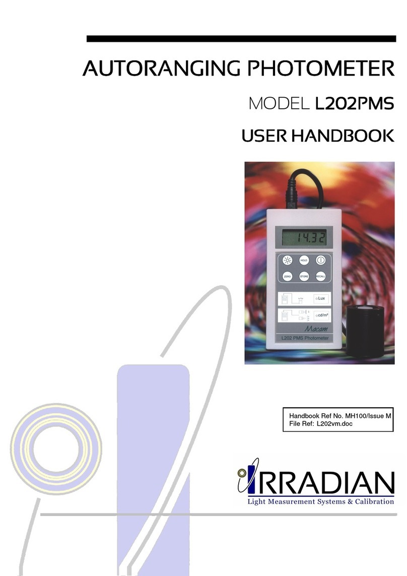
Irradian PM203 Instruction Manual

Handbook Ref No. MH065/Issue I
File Ref: PM203V3I.doc


1. Introduction
2. Specification
3. Operation
4. Battery Replacement
5. Calibration Description
6. Block Diagram
7. Programming via the RS232 interface
8. Environmental care, recycling and disposal


PM203 Radiometer Irradian Limited
1
The Irradian PM203 Optical Power Meter is a portable instrument
designed for accurate measurement of monochromatic light radiation in
Watts, dBm and dBr, covering the ultra violet visible and near infra red
parts of the spectrum.
The meters comprise of a hand held display unit, with microprocessor
control and a large led backlit 4½ digit liquid crystal display. The remote
detector assembly includes a multi-range amplifier and digitiser for low
noise measurements. The RS232 cable supplied allows connection to a
COM serial port on a computer for remote control and data logging.

Irradian Limited PM203 Radiometer
2
DISPLAY UNIT
Controller: 80C51 8bit micro-processor with a 3.1684MHz
clock.
Memory On board non volatile RAM for calibration
factors and set-up parameters.
Key Operation 8 switch key board with 9 LED indicators.
Power Switch Microprocessor reset at switch on.
Unit settings stored prior to shut down.
Serial Interface Three wire RS232 serial interface.
4800 baud, no parity, 1 stop bit.
Integration Time 0.33s
Conversion Scale 17 bit
Accuracy: Measurement accuracy ±1digit with a
linearity error of <1%.
Display: 4½ digit lcd display. Character height 10mm.
Display illumination: A LED back light can be switched on to
illuminate the display for readings in low
ambient light situations.
Power Supply: 9 volt PP3 battery.
Power Consumption: Shut down mode <5µA
Operating 10 - 20mA
LED back light ~20mA
Battery Life ~ 50 hours without back light use.

Irradian Limited PM203 Radiometer
3
(continued):
Standard Ranges:
5 full scale decades measuring from:
0 to 19.999 nW
0 to 199.99 nW
0 to 1.9999 µW
0 to 19.999 µW
0 to 199.99 µW
Resolution 0.001 nW on range 1.
Extended Range Option:
5 full scale decades measuring from:
0 to 199.99 nW
0 to 1.9999 µW
0 to 19.999 µW
0 to 199.99 µW
0 to 1.9999 mW
Resolution 0.01 nW on range 1.
Attenuators: Other measuring ranges are available when
the optical power meter is used in conjunction
with a calibrated attenuator or integrating
sphere.
Calibration Absolute calibration is traceable to National
Standards.
±5% - 400 to 1100nm.
±7.5% - 240 to 400nm.

Irradian Limited PM203 Radiometer
4
(continued):
PM203 Optical Power Meter
DETECTOR RS232
Figure 1
4½ digit LCD display
Measurement select button
Display backlight button
λselect decrease button
Background ZERO button
λselect increase button
Mode RESET button
Display HOLD Function REF button
Auto/manual RANGE button
Power switch button

Irradian Limited PM203 Radiometer
5
(continued):
Front Panel Controls:
RANGE Select auto ranging or manual range control.
UNITS Select between power in Watts (mW, µW and
nW) and dBm or relative dBr.
ZERO Initiates a zero or background measurement
routine on all five ranges.
HOLD/REF Display is held at present reading until HOLD
button is pressed again.
Select to set the reference level in dBr relative
measurements.
RESET Press to switch between 5nm λSelect and
Preset wavelengths.
λ
SELECT Use the
buttons to change the calibration
wavelength in 5nm steps throughout the range
of the detector or to select from the preset
wavelength table.
Power on / off button
Display backlight on off button.
Display backlight will switch off after a
programmable delay, factory setting 60 secs.
Connectors: 8 pin DIN type detector connector.
5 pin DIN type RS232 connector.
Temperature Range: 0 to 40°C. 80% RH.
Dimensions: 150 x 80 x 45mm.
High impact polystyrene.
Weight: 350g

Irradian Limited PM203 Radiometer
6
(continued):
LABORATORY DETECTOR, DET203PM
Amplifier PCB Photodiode
Cable
Accessory Mounting Thread
The DET203PM laboratory detector comprises of an aluminium housing,
photodiode and PCB assembly.
Detector: 100mm² silicon photodiode.
Spectral Response Ref. Figure 2
Temperature Coefficient: ~0 %/°C from 300 to 940nm
Amplifier Gain 10
8
V/A to 10
4
V/A
Current to Frequency 0 - 0.5Mhz
Linearity Error: <1% from 1nW to 100µW
Temperature Range: Operation: 0 to +40°C
Storage: -20 to +60°C
Detector Housing: Black anodised aluminium alloy housing.
Each optical accessory screws into the detector
housing on a 1.125" x 20 T.P.I.
The detector amplifier is connected to the
display unit via a multicore cable to a eight pin
DIN type connector.

Irradian Limited PM203 Radiometer
7
(continued):
SPECTRAL RESPONSIVITY OF SILICON DETECTOR
0.0
0.1
0.2
0.3
0.4
0.5
0.6
200 300 400 500 600 700 800 900 1000 1100
A
m
p
s
/
W
a
t
t
Wavelength (nm)
Figure 2

Irradian Limited PM203 Radiometer
8
SETTING UP
1) With the unit OFF, plug the detector 8 way connector into the socket
on the top of the display unit.
2) Ensure the photodiode window is clean.
3) Press and release the power switch on the PM203 display key pad.
The micro controller will initiate and search for the optimum amplifier
range with the display momentarily showing:-
Prior to displaying the power level the display will indicate the
calibration wavelength. A typical display is shown below.
Two LED’s will illuminate on the key pad to indicate the range units in
either Watts, dBm or dBr and the λSelect in either Preset or 5nm Step
mode. This will be the same settings prior to the last power off.
If the range was set to manual prior to switch off it may be necessary
to RESET or manually range to give a correct display.
For dBr measurements the reference level is held in the non volatile
memory prior to switch off and will only be updated when selecting the
dBr with the UNITS button.
4) Press and release the UNITS switch to select the units required.
5) It is recommended that the photometer amplifier is nulled periodically.
Place the cover over the filter ring or the end of the field of view probe.
Press and release the ZERO switch, the display will show:-

Irradian Limited PM203 Radiometer
9
(continued):
6) The micro controller will now measure the amplifier offset on each of
the five ranges and store these values in the non volatile memory. All
subsequent measurements will first have one of these offsets
subtracted before displaying the measurement.
At the end of the nulling sequence the display will show:-
Note if the photometer units are set to dBm the display will show
approximately -73.0, in dBr mode the display will depend on reference
level.
7) Remove the light cover from the detector. The equipment is now ready
for use.
Notes:
i) 1mW = 0 dBm, 0.5mW = -3dBm
dBm = 10 log
Reading (mW)
1mW
ii) To measure the power of a light beam the whole beam must
be within the active area of the photodiode.

Irradian Limited PM203 Radiometer
10
1) Switch off the photometer before changing the battery.
2) Slide open the battery compartment on the back of the photometer
and pull out the battery. Disconnect from the battery clip.
3) Replace with a PP3 9 volt battery.
4) Place battery inside compartment and slide cover closed.
5) Note it will be necessary to switch on and off the photometer before
normal operation will commence.
Irradian holds a number of tungsten halogen lamps, photometers and a
silicon photodiodes which are routinely calibrated by the National Physics
Laboratory in the UK.
Irradian estimates the absolute accuracy error in calibration of the PM203
optical power meter is ±5% from 400 to 1100nm for monochromatic light
source.
As with all measuring equipment a routine calibration is recommended,
typically annually, but with frequent use by a number of different users a
shorter recalibration period may be necessary.

Irradian Limited PM203 Radiometer
11
Detector
Amp
Gain Control
v to f Counter
µController
Keypad
Liquid Crystal
Display
Display Driver
RS232 Driver
& LEDs
Detector Amplifier
Micro-Controlled Display Unit
Non Volatile RAM

Irradian Limited PM203 Radiometer
12
!
! !
!
Serial Port Settings: 4800 baud, no handshaking
Single letter commands
S Toggle through possible amplifier gain ranges (manual mode)
Reset to autoranging mode with R command.
U Toggle through possible units, Watts, dBm and dBr.
F Increases calibration wavelength
I Decreases calibration wavelength
H Toggles hold/go
Z Zeros light meter
R Resets light meter
B Toggles backlight
s Sends data continuously via the RS232
o Sends one set of data via the RS232

Irradian Limited PM203 Radiometer
13
!
! !
!
(continued):
10.1 Windows 3.1 & Windows 95
Setting up remote control via Microsoft TERMINAL.EXE
1) Connect the cable between the RS232 socket on the light meter and
the COM port on the PC.
2) Switch on the light meter.
3) Run Terminal programme.
4) Go to the Settings / Communications screen and set the baud to 4800
and the COM port to suit.
5) Go to the Settings / Text Transfers and select Line at a time with
1/10th second delay.
6) Check the RS232 link by a switch to the manual range, LED on using
the command 'S', (capital S).
7) Reset to the auto range, LED off using the command 'R', (capital R).
8) Type 'o'for one packet of data and 's'for continuous data. Type 's'to
stop the data flow.
9) To save the terminal setup go to File / Save As and save the settings.
When restarting the programme the settings can be reloaded with File
/ Load filename. Now actions 4 and 5 can be omitted.
Logging data continuously to a file using Microsoft TERMINAL.EXE
1) Run the Terminal programme with the correct settings.
2) Set up the radiometer and send the command 's'via Terminal to
transmit data continuously from the radiometer.
3) Go to Transfers / Receive Text File. Enter filename for the stored data
(e.g. log1.txt).
4) On entering the file name, Terminal will now store all the readings
transmitted from the radiometer in a file log1.txt. The file is saved to
the computer by pressing STOP on the terminal screen.

Irradian Limited PM203 Radiometer
14
!
! !
!
(continued):
10.2 Windows 95 & Windows 98
Setting up remote control via Microsoft HYPERTERMINAL.EXE
1) Connect the cable between the RS232 socket on the light meter and
the COM port on the PC.
2) Switch on the light meter.
3) Run the HyperTerminal programme.
4) Enter a name for the session (e.g. UV203 etc.).
5) Select the type of connection required, either option 'direct to com 1'or
'direct to com 2'depending on which com port is to be used.
6) Enter the details for the serial connection: 4800 bits per second, 8 data
bits, no parity, 1 stop bit and no flow control.
7) Click the properties icon or select via the File / Properties option to
display the properties window.
8) Select the Settings tab and select Auto detect for the Emulation
setting.
9) Click the ASCII Setup button. Enter 100 into the box marked Line
delay. No other options are necessary. Click on OK to return to the
main window.
10) Check the RS232 link by downloading a reading using the command
'o', (lowercase o). This also allows auto detect to correctly identify the
meter settings, showing 4800 8-N-1 next to the Auto detect message
in the status bar. A reading should appear in the main window if the
connection has been made successfully.
11) To save the terminal setup go to File / Save As and save settings.
When restarting the programme the settings can be loaded directly by
double-clicking on the *.ht icon that has been created. Now actions 4
to 9 can be omitted.

Irradian Limited PM203 Radiometer
15
!
! !
!
(continued):
Logging data to a file using Microsoft HYPERTERMINAL.EXE
1) Run the HyperTerminal programme with the correct settings.
2) Set up the radiometer and send the command 's'via HyperTerminal to
transmit data continuously from the radiometer.
3) Go to Transfer / Capture Text. Enter the filename for the stored data
and the location to save to. (e.g. C:\HyperTerminal\Capture.txt).
4) Press the start button to store all the readings transmitted from the
radiometer in a file Capture.txt. The status bar will now show a
highlighted 'Capture'message. The file is saved to the computer by
selecting Transfer / Capture Text / Stop.
5) Send the command 's'again via HyperTerminal to stop the continuous
transitional of data from the radiometer.

Irradian Limited PM203 Radiometer
16
"
""
" !
! !
! #
# #
#
The purpose of the European Commission WEEE directive (Waste
Electrical and Electronic Equipment; 2002/96/EC) is to ensure that
electrical and electronic products are recycled using the best treatments,
recovery and recycling techniques that are currently available. This is so
that high health standards and a lasting environmental protection can be
achieved and maintained.
This product has been designed and manufactured using high quality
materials and components, many of which can be recycled and reused.
Please remember to observe the local regulations that govern both the
disposal of the packaging materials accompanying this product and any
used batteries.
DO NOT DISPOSE OF THIS PRODUCT IN YOUR
GENERAL WASTE BIN.
Please inform yourself about your local WEEE collection
system which is available for electrical and electronic
products that are marked with the symbol shown here.
When disposing of this meter, please use one of the following options:
1) Use your local designated WEEE collection facilities to dispose of the
complete product (including cables, detectors, filters & accessories).
2) Return the complete product back to Irradian, marking it clearly as
intended for WEEE disposal.
Table of contents
Other Irradian Measuring Instrument manuals

Irradian
Irradian L203 Instruction Manual

Irradian
Irradian PR450 Instruction Manual

Irradian
Irradian L203 SMU User manual

Irradian
Irradian L202PMS Instruction Manual

Irradian
Irradian PR203 Instruction Manual

Irradian
Irradian UV203 Instruction Manual

Irradian
Irradian PR203 User manual

Irradian
Irradian UV203-3 User manual

Irradian
Irradian UV201 Instruction Manual
Popular Measuring Instrument manuals by other brands

IET Labs
IET Labs LOM-510A Operation manual

Steelman
Steelman 60339 instruction manual

PCB Piezotronics
PCB Piezotronics IMI Sensors M606B61 Installation and operating manual

SDT International
SDT International SDT170 user manual

TESTO
TESTO 350 Maritime V2 instruction manual

Kobold
Kobold VKM operating instructions