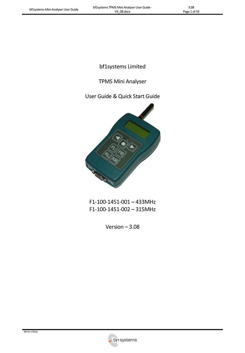
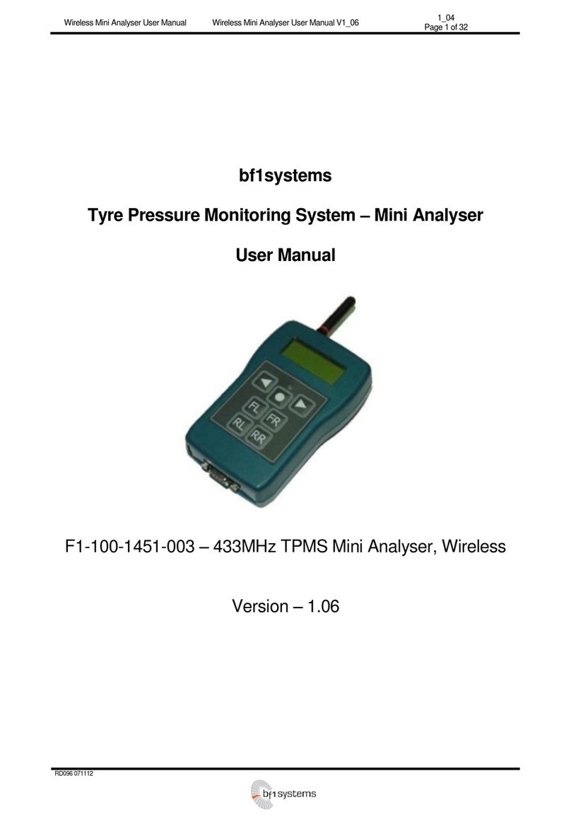
bf1 systems F1-100-1451-001 User manual

TPMS –Mini Analyser
Motorsport Mini Analyser Quick Start Guide -
V3_08.doc
3.08
Page 1 of 5
RD096 071112
bf1systems Ltd
TPMS –Mini Analyser
Quick Start Guide
F1-100-1451-001 –433MHz
F1-100-1451-002 –315MHz
Version –3.08

TPMS –Mini Analyser
Motorsport Mini Analyser Quick Start Guide -
V3_08.doc
3.08
Page 2 of 5
RD096 071112
1Analyser Overview –Button Functionality
1.1 Action Key
The Action Key is used to select menu options and to scroll through selection items. The Mini Analyser is also powered on and off
using the Action Key.
With the unit powered off, pressing and holding the Action Key will cause the unit to turn on. Depending upon configuration
settings the unit will display either the last page used or the main menu.
The unit can powered off from any screen by pressing and holding the Action Key.
1.2 Navigation Keys
The Navigation Keys are used for moving between screen display pages, and also for the selection of fields within pages
having multiple selectable items.
1.3 Position Assignment Keys
The position assignment keys are used to allocate sensors to given wheel positions as required for the generation of
wheel position and set data. Pressing a position assignment key immediately after the reception of a LF triggered datagram will
allocate the responding sensor to the selected position within the internally generated position (.pos) file. If a full set of wheel
sensors is learned consecutively then the user is prompted to assign the sensors as a wheel set. Position files generated within the
Mini Analyser can be uploaded to a PC and then transferred to the TPMS ECU.
1.4 Shortcuts
A number of keypad shortcuts are available to activate commonly used functions. These shortcuts operate from any Mini Analyser
display page.
1.5 Backlight
Simultaneously pressing the Navigation Keys toggles the display back light on and off.
1.6 Setup Menu
Simultaneously pressing the Left Navigation Key and the Action Key causes the analyser to enter the Setup Menu.

TPMS –Mini Analyser
Motorsport Mini Analyser Quick Start Guide -
V3_08.doc
3.08
Page 3 of 5
RD096 071112
1.7 Clear Set / Clear Positions
Simultaneously pressing the Position Assignment Keys will cause the Mini Analyser to clear any partially learned set data
held in temporary store. A splash screen is displayed to indicate the action has taken place.
Simultaneously pressing the Position Assignment Keys will cause the Mini Analyser to clear all position and set data held
within the unit. A splash screen is displayed to indicate the action has taken place.
2Permit List Upload
Before the Mini Analyser can be used it is a requirement that a permit list be loaded into the unit. bf1systems provide a permit list
whenever new wheel electronics are supplied. A permit list is transferred to the Mini Analyser using the PC DigiTyre utility in the
same manner for sending permit lists to the TPMS ECU on the car.
To connect the Mini Analyser to the PC software (DigiTyre Utility) follow the steps below:
Physically, connect the unit to the PC via an RS-232 cable
Power it on using the Action Key (see 2.3.1)
Run the DigiTyre utility. The Mini Analyser should be automatically connected via Comm Port 1. Also the software notifies the
user that the System is “Live” (see screenshot below).
The Mini Analyser will only recognise and display sensors contained within the loaded permit list. The use of permit lists prevents
other system owners interrogating sensors not belonging to them.
To load a permit list into the Mini Analyser, it should be connected to the PC. Using the < Update Permit List> page of the DigiTyre
utility the permit file (.pmt) is written to the analyser using the < Update TPMS> button at the bottom of the page.
Where ever possible bf1systems load a customer’s latest permit list prior to delivering a new Mini Analyser.

TPMS –Mini Analyser
Motorsport Mini Analyser Quick Start Guide -
V3_08.doc
3.08
Page 4 of 5
RD096 071112
RF [ MSport ] LF
Std :Mode: Std
9600 :Baud: 9600
Prev Toggle Next
3Setup Channel Config
The channel config options page allows the user to configure the Mini Analyser for different generations of bf1systems wheel
sensors. Changing this option affects the display pages of the < RF Receive> functions. Pressing the < Ok> button at the < Setup
Channel Config> page will enter the < Channel Config> options page.
Pressing the < Down> button whilst in the < Setup Channel Config> page will move to the < Setup Units> page. Pressing the < Up>
button whilst in the < Setup Channel Config> page will move to the < Setup Contrast> page.
Pressing the < Toggle> button cycles between the different types of wheels sensors that bf1systems manufacture.
Roche –Pharmaceutical application
IR –Single point IRTPTMS sensor
5PIXEL –5 points IRTPTMS sensor
5ChWTS –5channel rim temperature sensor
MSport –TPMS sensor
Auto –Not efficient due to the number of LF commands/RF data to encode/decode
Note: For V8 Supercars, “MSport” should be selected.
Once the required value has been set, holding down the Left Navigation Key returns to the < Setup Channel Config> page.
4RF Receive Menu –LF Setup
Depending on what state the Mini Analyser starts up in, press and hold the left hand arrow to return to the top level menu, when you
will see one of the screens shown below.
Press and release the left hand arrow until the <RF Receive> screen is selected, then press and release the centre button to enter the
RF Receive sub-menu. The first page you will enter onto is the individual sensor display.
The individual sensor display provides information regarding a single sensor. The Mini Analyser can be configured to display data
selectively based on the reported sensor mode, or to display data from any sensor that is received. This display page also provides a
facility to transmit selected LF codes and the means of allocating position and set data.
RFReceive
Up Ok Down
Setup
Up Ok Down
BatteryStatus
<##################>
Up Backlight Down

TPMS –Mini Analyser
Motorsport Mini Analyser Quick Start Guide -
V3_08.doc
3.08
Page 5 of 5
RD096 071112
4005294 BatOk 110
0.073bar STAT 51h
G1 19C 0 A R H M L
Up Tx:All Down
[ Trig : Always (3) ]
LF Trig
Gate Timeout:Off
Prev Toggle Next
4005294 - ID of received sensor
BatOk 110 - Sensor battery lifetime countdown (it starts at 120 and counts down with each internal process)
0.073bar - Uncompensated sensor pressure, bar/psi, gauge/abs set via <Setup Units> (see 2.7.1)
STAT 51h - Sensor operating mode
G1, G2, G3 - Sensor generation
19C - Sensor temperature reading, C/F selected via <Setup Units> (see 2.7.1)
0 - Sensor CRC
ARHML - Sensor mode flags
A –Auto transmit (no LF)
R –Roll switch active (moving)
H –Hardware error
M –Measurement error
L –LF triggered transmission
Pressing and releasing the centre key will cause the Mini Analyser to transmit the configured LF code. The LF settings are configured
via the <LF Setup> page. To enter the <LF Setup> page, hold down the right hand arrow.
The <LF Setup> page is used to configure the LF transmission of the Mini Analyser.
The <LF Setup> page should be set up as shown above. Once this is done, press and hold the left hand arrow key to return to the <RF
Receive> page.
With the <RF Receive> page selected, place the Mini Analyser within 30cm of a TPMS wheel sensor and press and release the centre
button to LF Trigger a wheel sensor and have the data from that wheel sensor displayed on the Mini Analyser’s screen like the one
below.
5250125 - ID of received sensor
BatOk 110 - Sensor battery lifetime countdown (it starts at 120 and counts down with each internal process)
T3= 45.5C - IR Tyre Temperature (single for the IR sensor or PIXEL3 for the 5PX). Rim temperature at point 3
when the 5ChWTS sensor is being used.
AMB=22.1C - Ambient temperature of the IR element. C/F selected via <Setup Units> (see 2.7.1)
5PX - Sensor generation
Pressing the< Up> or < Down> buttons navigate through to other <RF Receive> sub-menus to check other data transmitted from the
triggered sensor.
5250125 BatOk 110
T3= 45.5C AMB= 22.1C
5PX
Up Tx:All Down
Other manuals for F1-100-1451-001
1
This manual suits for next models
1
Table of contents
Other bf1 systems Measuring Instrument manuals
Popular Measuring Instrument manuals by other brands

Leica
Leica RANGEMASTER CRF 1000-R instructions

MONARCH INSTRUMENT
MONARCH INSTRUMENT Pocket Tach 99 instruction manual
Anritsu
Anritsu Field Master Pro Measurement guide
Siemens
Siemens SITRANS WF100 operating instructions

National Instruments
National Instruments NI PXI-6541 Getting started guide
Endress+Hauser
Endress+Hauser Proline Promag D 400 HART operating instructions
