English
Installation and operating instructions Wilo VR System 19
4 Description of the product and accessories
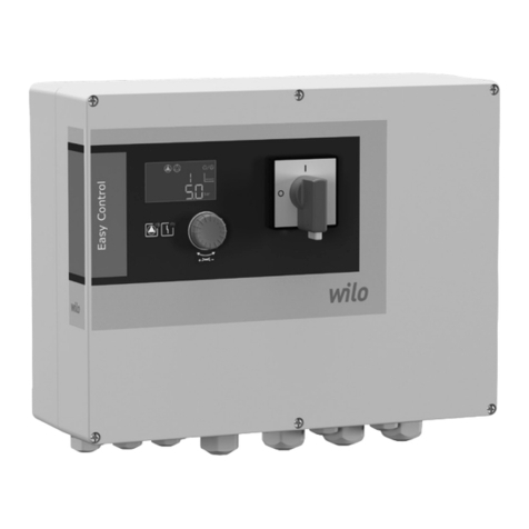
4.1 Description of the control device
4.1.1 Function description
The control device is for controlling and regulating
pressure boosting systems consisting of pumps
with integrated frequency converters or external
frequency converters. The pressure of a system is
controlled load-sensitively with appropriate signal
transmitters. The controller affects the frequency
converter which has an effect on the pump speed.
A change in speed changes the volume flow and
thus the rated motor power of the single pumps.
Depending on load requirements, pumps and asso-
ciated frequency converters are started or stopped.
The control device can control up to 4 pumps or
frequency converters.
4.1.2 Design of the control device
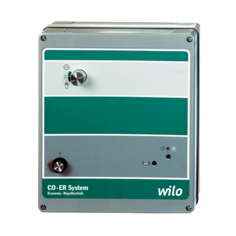
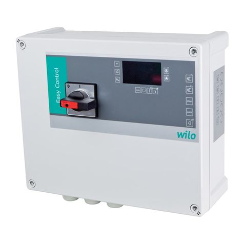
The standard control device consists of the fol-
lowing individual components (Fig. 2):
NOTE!
Fig. 2 merely shows an example.
The actual design may vary
according to the plant configuration.
The installations are in a sheet metal housing,
painted in RAL 7035 (textured):
•Main switch (item 1):
Disconnectsthe powersupply andis for connecting
the mains supply.
•Base board (item 2, design according to Fig. 3):
Power supply unit for the control device's low-
voltage part, fuses 6.3x32 (item 1), connector strip
forthedisplay board, microcontroller board (item 3)
and individualrun andfault messageboard (item 4).
In addition, connection terminals for the power
supply (Fig. 3, item 8) and for the external signals
(items 6+7), and slide switch (item 5) for every
pump for the system's emergency operation func-
tion and a potentiometer (item 5a) for setting the
speed.
•Microcontroller board (item 3):
Microprocessor and plug connections for the base
board and display board and DIP switches 1...8.
• Display board:
For LCD display, rotary knob and LEDs.
•Circuit breaker (item 5):
Fuse protection for the power supply of electronic
modules.
•Circuit breaker (item 4):
Fuse protection and connection of the single pumps
with frequency converter drives.
•Individual run and fault message board (item 6):
Optional, for the provisionof changeover contacts
for the run and fault signals of each pump and for
low water protection (see also Fig. 5).
Chapter 5 provides more information.
4.1.3 Operating modes of the system
Normal operation
An electronic pressure transducer provides the
actual system pressure value as 4 – 20 mA current
signal. Then the controller maintains the system
pressure constantly at the setpoint by means of
the comparison of the setpoint/actual value.
If there is no “External Off” signal and no fault, a
pump starts if required. The pump speed depends
on consumption.
If the required output cannot be covered by this
pump, another pump is started, the speed of which
is then controlled according to the reduction to
the pressure setpoint. Pumps, which are already
running, keep running at maximum speed. A zero-
flow test prevents the activation of a further pump,
provided there is no pressure drop.
If demand decreases to such an extent that the
controlling pump runs in its lowest performance
range and is not needed to cover demand, this
pump will be deactivated and the control function
is assigned to another pump which has previously
been working at maximum speed.
When the supply voltage is re-established after
deactivation or a power failure, the control device
is automatically switched to the previously set
operating mode.
Zero-flow cut-off
If only one pump is operated, whether a reduction
still applies is checked every 60 seconds. For this,
the pressure setpoint is increased slightly for a short
while and then reset again. If the actual system
pressure then remains at the higher level, there is
zero flow. The pump is then switched off after an
adjustable follow-up time, T2. If the pressure falls
below the setpoint, the system restarts. If T2 = 0
is set, zero-flow detection and deactivation are no
longer active.
Pump cycling
Two mechanisms are applied in order to ensure that
the loads on all pumps are distributed as evenly as
possible and to adjust the running times of the
pumps.
On the one hand, pump cycling is enforced after
a running time of 6 hours, including during normal
operation. For this, during peak-load operation,
the pump previously operated as peak-load pump
assumes the control function, which follows the
pump previously operated as base load (control)
pump. On the other hand, when the system is
restarted (e.g. after zero flow, “External Off”),
the pump that follows the pump last switched off
is started (provided there is no pump fault).
