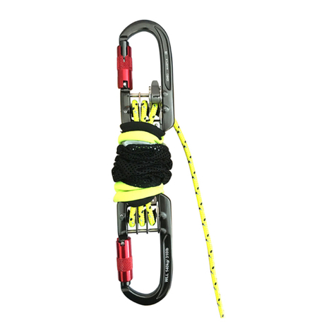
ISC D4 Instruction manual

1
RP88X series: Issue B - Feb 2018
DESCENDER
climb.work.rescue.
Work/Rescue Descender

2RP88X series: Issue B - Feb 2018
DESCENDER
+2
1
D4 PROtm Descender*D5 PROtm Descender*
D4tm Descender D5tm Descender
*[Q]
English
Český
Dansk
Deutsch
Español
Suomeski
Français
Italiano
Nederlands
Norsk
Polski
Português
Svenska
简体中文
日本語
General Instructions for Use
Obecnépokynykpoužití
Generelle brugerinstruktioner
Allgemeine Bedienungsanleitung
Instrucciones generales de uso
Yleinen käyttöohje
Instructions générales d’utilisation
Istruzioni generali d’uso
Algemene gebruiksinstructies
Generell bruksanvisning
Ogólneinstrukcjedotycząceużytkowania
Instruções gerais de utilização
Allmänna användarinstruktioner
的使用一般说明
使用のための一般的な手順
12
15
18
21
25
28
32
35
39
42
45
49
53
56
58
EN
CS
DA
DE
ES
FI
FR
IT
NL
NO
PL
PT
SV
ZH
JP

3
RP88X series: Issue B - Feb 2018
DESCENDER
Markings
A
NomenclatureB
Product name, brand
Rope size
Always read and follow the
instructions supplied by the
manufacturer.
Manufacturers
Part Code
controlling the
manufacture of
PPE.
S
tandards Year of manufacture/
Production batch/
Individual Serial number.
1
2
35
8
67
4
Moving side plate
Main Cam
Top Bobbin
Fixed side plate
Attachment point
Principal Materials:
Aluminium, Stainless Steel
Push button
Thumb Grip
Handle
7
1
2
3
5
6
4
8
YY/BBBBB/XX
Patent
GB1320103.3
Pending
RP880

4RP88X series: Issue B - Feb 2018
DESCENDER
Terminology
Cleaning
C
D
Max
30°
EN795
ANSI Z359.1
Brake hand Braking side of rope
AB
CAnchor

5
RP88X series: Issue B - Feb 2018
DESCENDER
Handle Position Inspection
E F
Installation on Rope
G
Operational Check
H
‘Click’
Primed
Descend
Panic
Park
4
1
2
3
R
e
s
e
t
5

6RP88X series: Issue B - Feb 2018
DESCENDER
Horizontal Movement
I
Foreseeable Misuse
J
Thumb grip

7
RP88X series: Issue B - Feb 2018
DESCENDER
Foreseeable Misuse
J

8RP88X series: Issue B - Feb 2018
DESCENDER
Work Positioning
Descent(work)
L
K
2m /per second
2m /per second
Click
Park

9
RP88X series: Issue B - Feb 2018
DESCENDER
(1)Expertuse(fortrainedoperators,withappropriateknowledgeandexperience)
M
RP220
Hand Ascender
Rigged for Rescue/Anchor
N
Ascending
PRIMED

10 RP88X series: Issue B - Feb 2018
DESCENDER
Pick off Rescue
O
RP890
REDtm Back-up Device RP209
Mini Ropegrab
Progress Capture/Horizontal Lines
P

11
RP88X series: Issue B - Feb 2018
DESCENDER
PRO Versions
Q
PRO
TM
0120
Primed
Descend
Park
1
2
3

12 RP88X series: Issue B - Feb 2018
DESCENDER
EN English
[D]Cleaning, inspection, and lubrication of descenders: After use, or at any time that the device
becomes soiled, cleaning may be effected by washing the device as follows:
Using warm <30°C water and mild household washing up detergent, use a soft cloth, or a nylon washing
up type brush for heavy soiling, to clean the exposed parts of the device.
Do not submerge the device completely in the detergent / water.
Rinse the device thoroughly in clean water, and allow to dry naturally, turning the device several times
during drying to ensure that trapped water is allowed to drain.
Apply a small quantity (i.e. 1 or 2 drops only) of light oil such as 3-in-1 oil as follows:
Push button: Open the moving side plate, depress the push button all the way in and apply a small
quantity of oil at the edge, depress and release several times ensure that the push button moves
smoothly and is not obstructed by debris, wipe of any excess oil with a rag.
Moving side frame: Apply a small quantity of oil under the edge of the rivet head, work the frame a few
times to distribute the oil, wipe off any excess oil with a rag.
Handle: Apply a small quantity of oil to the gap between the boss and the handle, rotate the handle
several times to distribute the oil, wipe off any excess oil with a rag.
Following cleaning carry out a pre use check as detailed in this manual.
If the device has been heavily soiled pay close attention to the motion of the parts to ensure that dirt and
foreign objects have not entered / compromised the mechanism.
If there is any doubt about the function of the unit it must be removed from use and serviced by a
competent person.
[E] Handle position: 1 - PARK, 2 - PRIMED, 3 - DESCEND, 4 - PANIC, 5 - RESET.
[F] Inspection: The wear indicator is a brass pin located-below the surface of the top bobbin. Ensure
this is not visible prior to use. If it is visible, the device should be removed from service.
Check for cracks, corrosion, sharp edges and deformation.
Check for loose fasteners / components.
Verify that the cam, when in PRIMED position, moves freely.
Ensure side plates align correctly.
Pay attention to the frame locking push button to ensure it engages fully into the moving side plate. You
will hear an audible ‘click’ when the frame seats correctly.
Verify that the handle rotates freely and that there are 3 audible ‘clicks’ during rotation. Check the
interaction of the cam and handle is fully functional. To do this:
1. Move the handle to the PRIMED position
2. Open the moving side plate to expose the cam
3. Apply and maintain pressure to the cam in the direction of the anchor
4. Pull the handle through DESCENT and into PANIC
While steps 3 and 4 are carried out the function of the handle and cam should move together. When the
handle reaches PANIC the cam must snap forwards in the direction of applied pressure.
[G] Installation on rope:
Connect the descender to your harness using a locking karabiner.
ISC recommend an Oval Karabiner.
Put the handle into PRIMED position to allow the cam to move freely.
Open the moving side plate
Insert the rope as indicated
Close the moving side plate
WARNING: The moving side plate must be properly engaged on the frame locking push button and the
karabiner must be tted through the attachment point of both frames. (See Fig J). Please be aware of
foreseeable misuse!
[H] Operational checks:Conduct all pre-use checks whilst using a backup safety system (recommended).
Before each use verify the correct installation of the rope.

13
RP88X series: Issue B - Feb 2018
DESCENDER
Ensure full handle rotation is not impeded or compromised.
WARNING: Do not let anything interfere with the correct operation of the descender or its components.
Ensure the handle of the descender and the gate of the connector do not come into contact with any
objects or surfaces which may impede its function or cause cross-loading – see misuse.
With the handle in the PRIMED position:
a. Try to pull the descender down the rope – it should not travel down the rope. If it does, check that the
rope is installed correctly, and that there is no sign of wear.
b. The descender should still travel up the rope.
Gradually put your weight on the descender, and with one hand holding the braking side of rope slowly
pull on the handle to allow the rope to slide through the descender. Ensure the movement can be
controlled and is smooth. If this does not work, check the installation of the rope.
Release the handle and check that the descender stops. If it does not stop do not continue to use the
descender.
[I] Horizontal movement / Traverse: On sloping or horizontal terrain, or with light loads the PANIC
brake activates easily. To enable you to travel smoothly, use the thumb-grip on the cam. NOTE: the
angle at which the device is held can affect the speed of the rope through the device.
[J] Forseeable misuse
[K]Descent(work):To control the descender in descent, your non-braking hand is used to control the
position of the handle, and your brake hand can be used on the braking side of rope, to give you extra
security and ne adjustment of speed control. If you pull the handle too far, whilst descending, the
descender will engage the PANIC function causing the descender to stop.
The PANIC function will be harder to engage if the braking side of rope is held rmly with the brake
hand, which is normal behaviour.
To RESET the descender, from the PANIC position, rotate the handle in the same direction (see Fig D).
This will allow you to continue your descent. Whilst it is not a requirement, if a second karabiner is used
to add friction to the system, you must ensure that it is located away from the main descender
attachment point – see Fig I.
[L] Work positioning: After stopping at your working position, lock the descender on the rope by
moving the handle in the opposite direction to that used for descent – ‘PUSH TO PARK’. Once you reach
the PARK position the handle will not travel any further in that direction (you should hear an audible
‘click’). To continue with your descent after completing your work, whilst holding the braking side of rope,
pull the handle to the PRIMED position and to begin your descent continue to rotate the handle.
[M] Ascending: With the descender in PRIMED position, using a hand ascender (RP220) take up slack
as you stand up. Never allow slack between the hand ascender and descender.
(1)Expertuse(fortrainedoperators,withappropriateknowledgeandexperience)
•It is important to fully understand the information provided in the ‘Expert use’ notice before using the
information provided.
•Mastering/carrying out these techniques requires training
•Consult with a professional before attempting to perform these techniques on your own for your safety.
[N] Rigged for rescue / Anchor: The handle of the descender must be in the PARK position. It must
be backed up using a suitable knot (e.g. Mule) with a suitable length of slack to allow slippage in the event
of overloading the system. In the event of a rescue, remove the knot and begin to lower.
Holding the braking side of rope, move the handle to PRIMED position, rotate the handle gradually to
allow the rope to slide through the descender. Control is aided by varying the grip on the braking side
of rope. To activate the self-braking function, release the handle. When the descender is lightly loaded,
if the PANIC function activates too easily, use the thumb-grip on the cam. Whilst it is not a requirement,
if a second karabiner is used to add friction to the system, you must ensure that it is located away from
the main descender attachment point – see Fig I.
[O] Pick-off rescue: The descender is rated for 240kg which allows for a variety of rescue scenarios.
Additional friction can be added if required, but is not always necessary.
[P] Progress capture/Horizontal lines: The descender can be used to capture the progress of a rope
at an anchor point of a horizontal line. With the handle in PRIMED position, the line can be tensioned,

14 RP88X series: Issue B - Feb 2018
DESCENDER
using a tensioning pulley and a ropegrab (RP209/RED) or by hand, until the desired tension is reached,
at which point the handle should be moved to the PARK position. It must be backed up using a suitable
knot (e.g. Mule) with a suitable length of slack to allow slippage in the event of overloading the system.
In the event of a rescue, remove the knot and begin to lower.
[Q] PRO Versions: The PRO versions of the D4 and D5 work rescue descenders are not equipped with a
panic brake feature.The user must descend at a suitable speed. All other functions remain the same.
Minimum approximate slip loads (to reduce impact forces):
D4 – 5kN*
D5 – 9kN*
*rope condition and/or size may affect these gures.
Extremecaremustbetakenwhenworkingwithhorizontallinessinceitispossibletocreate
excessiveforcesandoverloadingoftherope,anchors,andhardware–specialisttrainingand
knowledgeisrequiredtoensurethatthistypeofsystemisriggedandoperatedsafely.
When to retire your equipment
• If the descender is subjected to a load greater than the slip load, such as might be experienced in a
dynamic load event
• If the brass wear indicator in the top bobbin is visible
• It fails to pass inspection
• You do not know its full usage history
• If there is any doubt with the condition or reliability
• When it becomes obsolete due to changes in standards, legislation, technique or incompatibility with
other equipment
• If the rope path over the moving side frame has worn through completely.
Ensuretheequipmentisdestroyedtopreventfurtheruse.
Legislation
The ISC descender is an EN12841:2006 Type C rope adjustment descender. The primary function of the
descender is progression along the working line. The descender must be used in conjunction with a Type
A backup descender (e.g. ISC RED) on a second rope (safety rope). The descender is not suitable for use
in an EN363 fall arrest system. Certication testing was carried out at SATRA Technology Centre (NB0321)
and was performed using 240kg mass using Mammut Performance Static 10.5mm and BEAL Industrie
11.5mm ropes.
The descender must be used with an anchor point/system, located above the user, conforming with EN795
or in accordance with ANSI z359, or any other specic recognised International Standard or industry best
practice relating to the specic use, or a non-engineered anchor point capable of withstanding appropriate
loads.
To reduce the risk of a free fall, the rope between the rope adjuster and the anchor must always be taut.
Make sure that the anchor point is correctly positioned, in order to limit the risk and the length of a fall.
The anchor should be positioned such that the free movement of the system, and the fall path is
unobstructed. Work as closely to, directly below the anchorage point as is possible (maximum 30°from
vertical) to avoid swing-fall injury.
NotiedBodyhavingcarriedouttheCEtypetest(Art.10):SATRATechnologyCentre(0321),
Wyndham Way, Telford Way, Kettering, Northamptonshire, NN16 8SD. U.K.
Notied body responsible for production monitoring and inspection (Art. 11B): SGS United
KingdomLtd(0120),Unit202B,WorleParkway,WestonSuperMare.S226WA.U.K.

15
RP88X series: Issue B - Feb 2018
DESCENDER
Musíte si přečíst tyto pokyny společně s dodanými všeobecnými pokyny a plně porozumět
jejich obsahu.
[A] Značení.
1 - Název výrobku, značka DXtm
2 – Označení výrobce.
3 – Oznámený subjekt pověřený kontrolou výroby OOP.
4 – Vždy si přečtěte a dodržujte pokyny dodané výrobcem.
5 – Průměr a typ lana: RP880xx (D4) – EN 1891A (10,5–11,5 mm)
RP883xx (D5Y) – NFPA ‘T’ 7/16” Armortech (11,1–12 mm)
RP885xx (D5) – NFPA ‘G’ ½” (12,5–13 mm)
6 – Normy
7 – Sériové číslo: YY – rok, BBBBB – výrobní série, XX – individuální sériové číslo.
8 – Partcode.
[B]Pojmenovánísoučástí.
1 – pohyblivá bočnice, 2 – vačka, 3 – vrchní kladka, 4 – rukojeť, 5 – pevná bočnice, 6 – tlačítko, 7 -
závěsný otvor, 8 – palcová svěrka.
Hlavní materiály: Hliník, nerezová ocel
[C]Názvosloví: A - Brzdná ruka, B - brzdicí strana lana.
[D]Čištění,kontrolyamazáníslaňovacíchbrzd:Po použití nebo kdykoli v případě znečištění lze
zařízení vyčistit tak, že se omyje následujícím způsobem:
K čištění odkrytých částí zařízení použijte teplou vodu o teplotě <30 °C se slabým saponátem na nádobí,
měkkou látku nebo, v případě silného znečištění, nylonový kartáč na nádobí.
Neponořujte celé zařízení do saponátu/vody.
Důkladně opláchněte zařízení čistou vodou a nechte ho uschnout na vzduchu; během schnutí ho několikrát
obraťte, aby mohla vyschnout zachycená voda.
Na následující součásti naneste malé množství (tj. pouze jednu nebo dvě kapky) lehkého univerzálního
oleje:
Tlačítko: Otevřete pohyblivou bočnici, stiskněte tlačítko až na doraz, naneste na okraj malé množství
oleje, několikrát toto tlačítko stiskněte a uvolněte, abyste ověřili, zda se volně pohybuje a není blokováno
nečistotami, a nadbytečný olej setřete hadrem.
Pohyblivábočnice: Naneste malé množství oleje pod okraj hlavy nýtu, několikrát zahýbejte bočnicí,
aby se olej roznesl, a nadbytečný olej setřete hadrem
Rukojeť: Naneste malé množství oleje do mezery mezi výčnělkem a rukojetí, několikrát otočte rukojeť,
aby se olej roznesl, a nadbytečný olej setřete hadrem.
Po vyčištění proveďte kontrolu před použitím podle popisu v tomto návodu.
Pokud bylo zařízení silně znečištěné, věnujte pozornost pohybu součástí, abyste se ujistili, že do
mechanismu nevnikly nebo jej nenarušily nečistoty a cizí předměty.
Máte-li jakékoli pochybnosti týkající se funkčnosti zařízení, musíte ho vyřadit z provozu a předat způsobilé
osobě k servisní opravě.
[E] Polohy rukojeti – 1 - PARKOVÁNÍ, 2 - PŘIPRAVENO, 3 - SESTUP, 4 - PANIKA, 5 - REAKTIVOVAT.
[F] Kontrola: Jako indikátor opotřebení slouží mosazný kolík umístěný pod povrchem vrchní kladky. Před
použitím se ujistěte, že není vidět. Pokud je vidět, zařízení by se mělo vyřadit z provozu.
Zkontrolujte, zda na zařízení nejsou praskliny, koroze, ostré hrany a deformace.
Zkontrolujte upevňovací prvky/součásti, zda nejsou uvolněné.
Ověřte volný pohyb vačky v poloze PŘIPRAVENO.
Ujistěte se, že bočnice jsou správně vyrovnané.
Věnujte pozornost zajišťovacímu tlačítku rámu, abyste se ujistili, že se úplně zasune do pohyblivé
bočnice. Při správném usazení rámu se ozve slyšitelné „cvaknutí“.
1. Otočte rukojeť do polohy PŘIPRAVENO.
2. Otevřete pohyblivou bočnici, abyste odkryli vačku.
3. Zatlačte a udržujte tlak na vačku ve směru kotevního bodu.
4. Zatáhněte Běhemprováděníkroků3a4bysemělyrukojeťavačka
Český
CS

16 RP88X series: Issue B - Feb 2018
DESCENDER
Během provádění kroků 3 a 4 by se měly rukojeť a vačka pohybovat společně. Když rukojeť dosáhne
polohy PANIKA, vačka musí přeskočit dopředu ve směru působícího tlaku.
[G]Založenílana.
Připojte slaňovací brzdu pomocí karabiny se zámkem k postroji.
Společnost ISC doporučuje oválnou karabinu.
Umístěterukojeť do polohy PŘIPRAVENO, aby se mohla vačka volně pohybovat.
Otevřete pohyblivoubočnici.
Založte lano podle znázornění na obrázku.
Zavřete pohyblivoubočnici.
VAROVÁNÍ: Pohyblivá bočnice musí být správně spojena se zajišťovacím tlačítkem rámu a karabina musí
procházet závěsnými otvory obou rámů (viz obr. J). Pamatujte na možnost chybného použití!
[H]Kontrolyfunkčnosti: Proveďte všechny přípravné kontroly s použitím záložního bezpečnostního
systému (doporučeno).
Před každým použitím ověřte správné založení lana.
Ujistěte se, že nic nepřekáží ani nebrání úplnému otáčení rukojeti.
VAROVÁNÍ: Nedopusťte, aby cokoli narušilo správnou funkčnost slaňovací brzdy nebo jejích součástí.
Ujistěte se, že rukojeť slaňovací brzdy a uzávěr karabiny nejsou ve styku se žádnými předměty nebo
povrchy, které by mohly narušit jejich funkčnost nebo způsobit příčné zatížení – viz chybné použití.
SrukojetívpolozePŘIPRAVENO:
a. Zkuste zatáhnout slaňovací brzdu dolů po laně – neměla by se pohybovat dolů. Pokud se pohybuje
dolů, zkontrolujte, zda je správně založené lano a zda nejsou patrné žádné známky opotřebení.
b. Slaňovací brzda by se stále měla pohybovat po laně nahoru.
Postupně zatěžujte slaňovací brzdu a s jednou rukou držící brzdicístranulana pomalu zatáhněte za
rukojeť, aby mohlo lano prokluzovat slaňovací brzdou. Ujistěte se, že pohyb lze ovládat a je vyrovnaný.
Pokud to nefunguje, zkontrolujte založení lana
Uvolněte rukojeť a zkontrolujte, zda se slaňovací brzda zastaví. Pokud se nezastaví, již ji nepoužívejte
[I]Vodorovný/příčnýpohyb. Ve svažujícím se nebo vodorovném terénu nebo při lehkém zatížení
se snadno aktivuje funkce brzdy PANIKA. Použijtepalcovousvěrku na vačce, která vám umožní
vyrovnaný pohyb. POZNÁMKA: rychlost průchodu lana zařízením může být ovlivňován úhlem, ve kterém
se zařízení drží.
[J]dohlednézneužití
[K] Sestup (pracovní). Při sestupu se slaňovací brzda ovládá tak, že nebrzdná ruka slouží k ovládání
polohy rukojeti a brzdná ruka se používá na brzdicí straně lana za účelem zvýšení bezpečnosti a
jemného přizpůsobování rychlosti. Pokud během sestupu příliš zatáhnete za rukojeť, slaňovací brzda
aktivuje funkci PANIKA, která způsobí, že se brzda zastaví.
Pokud budete brzdnou rukou pevně držet brzdicístranulana, což je normální chování, funkce PANIKA
se nebude aktivovat tak snadno.
Chcete-li REAKTIVOVAT slaňovací brzdu z polohy PANIKA, otáčejte rukojeť stejným směrem (viz obr. D).
Pak budete moci pokračovat v sestupu. Není nutné používat druhou karabinu ke zvýšení tření v systému,
nicméně pokud se použije, musíte zajistit, aby se nacházela dále od závěsnéhootvoru hlavní slaňovací
brzdy – viz obr. I.
[L]Dosaženípracovnípolohy. Až se zastavíte v pracovní poloze, zajistěte slaňovací brzdu na laně tak,
že otočíte rukojeť opačným směrem než při sestupu – „ZATLAČENÍM ZAPARKUJTE“. Jakmile se dostane
rukojeť do polohy PARKOVÁNÍ, již se nebude pohybovat dále tímto směrem (mělo by se ozvat slyšitelné
„cvaknutí“). Chcete-li po dokončení práce pokračovat v sestupu, držte brzdicí stranu lana, zároveň
zatáhněte rukojeť do polohy PŘIPRAVENO a dalším otáčením rukojeti zahajte následný sestup.
[M] Vzestup: Se slaňovací brzdou v poloze PŘIPRAVENO naberte ve stoje pomocí ručního blokantu
(RP220) délku volného lana. Nikdy nedopusťte, aby bylo lano mezi ručním blokantem a slaňovací brzdou
volné.

17
RP88X series: Issue B - Feb 2018
DESCENDER
(1)Odbornépoužívání(prokvalikovanéosobysnáležitýmiznalostmiazkušenostmi)
• Před postupováním podle těchto informací je důležité plně porozumět informacím uvedeným v
upozornění Výjimečné způsoby používání.
• Ke zvládnutí/provádění těchto technik je nutný výcvik
• Než přistoupíte k provádění těchto technik, v zájmu vlastní bezpečnosti se poraďte s profesionálem.
[N]Záchranářskávýstroj/kotevníbod: Rukojeť slaňovací brzdy musí být v poloze PARKOVÁNÍ. Brzda
musí být jištěna vhodným uzlem (např. zajištěnou půllodní smyčkou)
s vhodnou délkou volného lana, které umožní skluz v případě přetížení systému. V případě záchrany
odstraňte uzel a zahajte spouštění.
Minimální přibližné kluzné zatížení (na snížení rázové síly):
D4 – 5 kN*
D5 – 9 kN*
*tyto hodnoty mohou být ovlivněny stavem a/nebo průměrem lana.
Zatímco budete držet brzdicí stranu lana, umístěte rukojeť do polohy PŘIPRAVENO a postupným
otáčením rukojeti nechte lano prokluzovat slaňovací brzdou. Změny sevření úchopu na brzdicístraně
lana pomohou lépe ovládat pohyb. Chcete-li aktivovat funkci samočinného brzdění, uvolněte rukojeť.
Pokud se příliš snadno aktivuje funkce PANIKA při lehkém zatížení slaňovací brzdy, použijte palcovou
svěrkuna vačce. Není nutné používat druhou karabinu ke zvýšení tření v systému, nicméně pokud se
použije, musíte zajistit, aby se nacházela dále od závěsnéhootvoru hlavní slaňovací brzdy – viz obr. I
[O]Záchrannévytahování: Slaňovací brzda je dimenzována na hmotnost 240 kg, proto ji lze používat
v různých záchranných situacích. V případě potřeby lze dále zvýšit tření, obvykle to však není nutné.
[P] Dobírání lana/vodorovná lana: Slaňovací brzdu lze použít k dobírání lana v kotevním bodě
vodorovného lana. S rukojetív poloze PŘIPRAVENO lze lano napínat pomocí napínací kladky a blokantu
(RP209/RED) nebo rukou, dokud se nedosáhne požadovaného napnutí; v tom okamžiku je třeba přemístit
rukojeť do polohy PARKOVÁNÍ. Brzda musí být jištěna vhodným uzlem (např. zajištěnou půllodní
smyčkou) s vhodnou délkou volného lana, které umožní skluz v případě přetížení systému. V případě
záchrany odstraňte uzel a zahajte spouštění.
[Q] PRO verze: PRO verze záchranářských slaňovacích brzd D4 a D5 nedisponují funkcí panika. Uživatelé
musí slaňovat přiměřenou rychlostí. Veškeré ostatní funkce zůstávají beze změny.
Při práci na vodorovných lanech je nutné dbát krajní opatrnosti, protože mohou vznikat
nadměrnésílyamůžedojítkpřetíženílana,kotevavybavení–vyžadujeseodbornéškolenía
znalosti,kterézaručíbezpečnésestaveníapoužívánísystémutohototypu.
Kdyvyřaditzařízení
• Pokud je slaňovací brzda vystavena většímu než předepsanému kluznému zatížení, k čemuž může dojít
v případě dynamického zatížení.
• Pokud je vidět mosazný indikátor opotřebení ve vrchníkladce.
• Pokud neprojde kontrolou.
• Jestliže neznáte jeho dosavadní historii používání.
• Pokud máte jakékoli pochybnosti o jeho stavu nebo spolehlivosti.
• Když zastará v důsledku změn v normách, právních předpisech či technikách nebo v důsledku
nekompatibility s ostatním vybavením.
• Pokud je dráha lana na pohyblivébočnici zcela opotřebená.
Zajistěte,abybylozařízenízničenoatímsepředešlojehodalšímupoužívání
Právní předpisy
Slaňovací brzda ISC je nastavovací zařízení lana typu C podle normy EN 12841:2006. Základní funkcí
slaňovací brzdy je pohyb po pracovním laně. Slaňovací brzda se musí používat společně se záložní
slaňovací brzdou typu A (např. ISC RED) na druhém (pojistném) laně. Tato slaňovací brzda není vhodná
k používání v systému ochrany osobproti pádu podle normy EN 363.

18 RP88X series: Issue B - Feb 2018
DESCENDER
Homologační zkouška byla provedena v Technologickém středisku SATRA (NB0321) s použitím 240kg
závaží a lan Mammut Performance Static 10,5 mm a BEAL Industrie 11,5 mm.
Tato slaňovací brzda se musí používat s kotvicím zařízením/systémem vyhovujícím normě EN 795,
předpisu ANSI Z359 nebo jakékoli jiné uznávané mezinárodní normě či osvědčeným postupům týkajícím
se daného způsobu používání, nebo s nestandardizovaným kotvicím zařízením, které dokáže vydržet
příslušné zatížení.
Skoba by měla být umístěna nad uživatelem, aby byl zajištěn volný pohyb systému a slaňovací dráhy.
Pracujte co nejblíže bodu ve kterém je umístěna skoba, abyste se vyhnuli zranění způsobeným kýváním
lana při slaňování (efekt kyvadla).
Vyvarujte se prověšení zajišťovacího vedení mezi uživatelem a kotvy
Denne brugsanvisning skal læses og forstås til fulde i forbindelse med de almindelige leverede
anvisninger.
[A] Markeringer.
1 - Produktnavn, mærke DXtm
2 – Fabrikantens ID.
3 - Bemyndiget organ der kontrollerer fremstillingen af PV.
4 - Læs og overhold altid de anvisninger, der er medgivet af fabrikanten.
5 - Rebstørrelse og -type: RP880xx (D4) – EN1891A (10.5 – 11.5mm)
RP883xx (D5Y) – NFPA ‘T’ 7/16” Armortech (11.1 – 12mm)
RP885xx (D5) – NFPA ‘G’ ½” (12.5 – 13mm)
6 - Standarder
7 - Serienummer: YY – år, BBBBB – Produktionsparti, XX – individuelt serienummer.
8 – del kode
[B] Systematisk fortegnelse over dele.
1 - Bevægeligt sideblik, 2 - Låsekam, 3 - Topspole, 4 - Håndtag, 5 - Stationært sideblik, 6. - Trykknap,
7 - Fastgørelsespunkt, 8 - Tommelngergreb
Primære materialer: Aluminium, rustfri stål.
[C] TERMINOLOGI: A - Bremsehånd, B - bremseside af reb.
[D] Rengøring, inspektion og smøring af descendere:
Efter brug, eller hver gang anordningen bliver snavset, kan den rengøres ved at vaske den som følger:
Under anvendelse af < 30 °C varmt vand og et mildt husholdningsopvaskemiddel skal du anvende en blød
(evt. nylon-) opvaskebørste til at fjerne grov snavs fra de udsatte steder på anordningen
Anordningen må ikke dyppes helt ned i rensemiddel /vand.
Skyl anordningen grundigt i rent vand, og lad den tørre i luften, og vend den ere gange under tørringen
for at sikre at vand, der gemmer sig indeni, kan løbe ud.
Påfør en lille smule (dvs. blot 1 eller 2 dråber) let olie, som f.eks. syrefri hobbyolie som følger:
Trykknap: Åbn det bevægelige sideblik, tryk trykknappen helt i bund, og påfør en lille smule olie på
kanten. Nedtryk og udløs trykknappen ere gange for at sikre, at den kan bevæges uhindret og ikke er
blokeret af urenheder. Tør evt. overskydende olie af med en klud.
Det bevægelige sideblik: Påfør en lille smule olie under kanten af nittehovedet, kør blikket et par
gange frem og tilbage for at fordele olien, og aftør evt. overskydende olie med en klud.
Håndtag: Påfør en lille smule olie i revnen mellem navet og håndtaget, og drej håndtaget ere gange
for at fordele olien, og aftør evt. overskydende olie med en klud.
Efter rengøring skal der udføres et tjek inden brug, som anvist i denne manual.
Hvis anordningen er blevet meget snavset, skal du være særlig opmærksom på, at delene kan bevæges
frit for at sikre, at snavs og fremmedlegemer ikke er trængt ind i / har gjort mekanismen upålidelig.
Hvis der er nogen som helst tvivl omkring enhedens funktion, skal den tages af brug og sendes til service
hos en kompetent person.
DA Dansk

19
RP88X series: Issue B - Feb 2018
DESCENDER
[E] Håndtagsposition: 1- PARKERET, 2 - KLAR, 3 - NEDFIRING, 4 - PANIK, 5 - NULSTIL.
[F] Inspektion: Slitageindikatoren er en messingpind, der bender sig nede under overaden på
topspolen. Forvis dig om, at den ikke er synlig inden brug. Hvis den kan ses, skal anordningen tages ud
af drift.
Tjek for revner, korrosion, skarpe kanter og deformation.
Tjek for løse strammere / komponenter.
Tjek at låsekammen, når den er i positionen KLAR, kan bevæges frit.
Sørg for at sideblikkene er korrekt ud for hinanden.
Vær opmærksom på trykknappen, der låser rammen, for at være sikker på, at den er helt i indgreb med
det bevægelige sideblik. Man kan høre et hørbart ‘klik’, når rammen går korrekt i hak.
Forvis dig om, at håndtaget kan drejes frit, og at der er 3 hørbare ‘klik’, når det drejes. Kontroller, at
låsekammen og håndtaget fungerer korrekt sammen. Det gøres således:
1. Drej håndtaget hen på positionen KLAR.
2. Åbn det bevægelige sideblik for at blotlægge låsekammen.
3. Anvend og hold tryk på låsekammen i retning af ankeret.
4. Træk håndtaget forbi NEDFIRING og hen på PANIK.
Under udførelsen af trin 3 og 4 skal håndtagets og låsekammens funktion være synkron. Når
håndtaget kommer hen på PANIK, skal låsekammen smutte fremad i retning af det anvendte tryk.
[G] Installation på rebet.
Sæt descenderen på dit seletøj vha. en karabinhage.
ISC anbefaler en oval karabinhage.
Før håndtaget hen på positionen KLAR for at låsekammen kan bevæges frit.
Åbn det bevægelige sideblik.
Indfør rebet som vist.
Luk det bevægelige sideblik.
ADVARSEL: Det bevægelige sideblik skal være korrekt i indgreb på rammens trykknap, og
karabinhagen skal være anbragt gennem begge rammers fastgørelsespunkt. (Se g. J). Vær
opmærksom på forkert brug, der kan forekomme!
[H] Betjeningstjek. Udfør alle tjek inden brug under anvendelse af et backup-sikkerhedssystem
(anbefales).
Inden hver brug skal det kontrolleres, at rebet er korrekt isat.
Forvis dig om, at håndtagets rotation ikke er hæmmet eller på anden måde forhindret.
ADVARSEL: Du må ikke tillade, at noget som helst forhindrer, at descenderen eller dens komponenter
fungerer korrekt. Pas på, at håndtaget på descenderen og konektorens åbning ikke kommer i kontakt
med nogen genstande eller overader, der kan hæmme dets funktion eller forårsage krydsbelastning - se
Forkert brug.
Med håndtaget i positionen KLAR:
a. Prøv at trække descenderen ned ad rebet - det må den ikke kunne! Hvis den kan trækes nedad, skal
du tjekke, at rebet er påsat korrekt, og at der ikke er tegn på slitage.
b. Descenderen skal stadig kunne bevæges op ad rebet.
Anlæg gradvist din vægt på descenderen, og mens du med den ene hånd holder fast på bremsesiden af
rebet, trækker du langsomt i håndtaget, så rebet kan glide gennem descenderen. Kontroller at bevæ-
gelsen kan styres og er jævn. Hvis dette ikke fungerer, skal du tjekke rebets installation.
Slip håndtaget, og tjek at descenderen stopper. Hvis den ikke stopper, må du ikke fortsætte med at
bruge descenderen.
[I] Horisontal bevægelse / travers. På skrånende eller horisontalt terræn eller ved lette belastninger
aktiveres PANIK-bremsen let. For at kunne bevæge sig jævnt, skal du bruge tommelngergrebet på
låsekammen. BEMÆRK: Den vinkel, hvormed anordningen holdes, kan have indydelse på, hvor hurtigt
rebet bevæger sig gennem anordningen.
[J] Forudses

20 RP88X series: Issue B - Feb 2018
DESCENDER
[K]Nedstigning(arbejde).Descenderen styres under nedstigning ved at bruge ikke-bremsehånden
til at kontrollere håndtagets position, og bruge bremsehånden på bremsesiden af rebet for at give
ekstra sikkerhed og njustering af hastighedskontrollen. Hvis du trækker håndtaget for langt rundt, går
descenderen i PANIK-funktionen, og descenderen stopper.
PANIK-funktionen går ikke så let i indgreb, hvis bremsesiden af rebet holdes fast med bremsehånden,
hvilket er normal adfærd.
Descenderen NULSTILLES fra PANIK-positionen ved at dreje håndtaget i samme retning (se g. D). Dette
vil lade dig fortsætte din nedstigning. Selvom det ikke er et krav, skal du, hvis endnu en karabinhage
bruges for at give friktion på systemet, sikre dig, at den ikke bender sig i nærheden af descenderens
hovedfastgørelsespunkt - se g. I.
[L] Arbejdsplacering. Efter at have stoppet i din arbejdsposition, skal du låse descenderen på rebet
ved at føre håndtaget i modsat retning af den, der benyttes til nedstigning - ‘SKUB FOR AT PARKERE’.
Når håndtaget går i PARKERINGS-position, kan det ikke drejes længere i den retning (man skal kunne
høre et hørbart ‘klik’). For at fortsætte nedstigningen efter at være blevet færdig med dit arbejde, skal
du, mens du holder fast på bremsesiden af rebet, trække håndtaget hen på KLAR-positionen og dreje
håndtaget videre for at fortsætte nedstigningen.
[M] Opstigning: Med descenderen i KLAR-position skal du ved brug af en hånd-ascender (RP220)
efterhånden som du stiger op. Der må aldrig være løst reb mellem ascenderen og descenderen.
(1)Ekspertbrug(fortrænedebrugere,medkorrektkendskabogerfaring)
• Det er vigtigt at forstå de informationer, der gives i notitsen Særlige anvendelser, helt, inden der gøres
brug af dem.
• Det kræver træning at mestre/udføre disse funktioner.
• Rådfør dig med en professionel klatrer, inden du begynder at udføre disse funktioner alene, for din
sikkerheds skyld.
[N] Rigget til til redning / anker: Håndtaget på nedstigningsanordningen skal være i PARKERET-
positionen. Det skal suppleres ved at bruge en passende knude (f.eks. en hornknast) med en passende
længde løst reb, der tillader glidning, hvis systemet overbelastes. Ved redning fjernes knuden, og
nedring påbegyndes.
Minimale omtrentlige glidningsbelastninger (til reducering af slagkræfter):
D4 – 5kN*
D5 – 9kN*
*rebets tilstand og/eller størrelse kan have indydelse på disse tal.
Mens du holder bremsesiden af rebet, føres håndtaget hen på KLAR-positionen, og drej håndtaget
gradvist, så rebet kan glide gennem descenderen. Kontrollen bistås ved at variere grebet om bremsesiden
af rebet. Self-bremsefunktionen aktiveres ved at slippe håndtaget. Hvis PANIK-funktionen aktiveres for
let, når descenderen kun er let belastet, skal du bruge tommelngergrebet på låsekammen. Selvom
det ikke er et krav, skal du, hvis endnu en karabinhage bruges for at give friktion på systemet, sikre dig,
at den ikke bender sig i nærheden af descenderens hovedfastgørelsespunkt - se g. I.
[O] Redning af enkeltmand: Descenderen er nomineret til 240 kg, hvilket giver mulighed for en
mangfoldighed af redningssituationer. Der kan tilføres ekstra friktion, hvis det kræves, men det er ikke
altid nødvendigt.
[P] Opfangning af reb/Horisontale liner: Descenderen kan bruges til at opfange et rebs fremgang
på et ankerpunkt til en horisontal line. Med håndtaget i KLAR-position kan linen strammes vha. en
strammerulle og en rebgriber (RP209/RED) eller manuelt, indtil den ønskede stramning er opnået,
på hvilket punkt håndtaget skal drejes om i PARKERET-position. Det skal suppleres ved at bruge en
passende knude (f.eks. en hornknast) med en passende længde løst reb, der tillader glidning, hvis
systemet overbelastes. Ved redning fjernes knuden, og nedring påbegyndes.
[Q] PRO-versioner: PRO-versionerne D4 og D5 arbejdsrednings-descenderne er ikke forsynet med en
panikbremsefunktion. Brugeren skal stige ned ved en passende hastighed. Alle andre funktioner er de
samme.
Other manuals for D4
1
This manual suits for next models
5
Table of contents
Languages:
Other ISC Security Sensor manuals
Popular Security Sensor manuals by other brands

Sundstrom
Sundstrom SR 540 EX Instructions for use

Fisher Research Labs
Fisher Research Labs XLT-17 operating manual

Visonic
Visonic Elpas Wiring guide

BubblyNet
BubblyNet steinel S-HT-C12-DRWH manual

Source Innovations
Source Innovations Cordless Teth-Air user manual

Kyongbo Electric
Kyongbo Electric GD8-L05A user manual

Becker
Becker Centronic SensorControl SC711A Assembly and operating instructions

AMC
AMC SS900 Installer manual

Balluff
Balluff BTL7-C/E509-M Series user guide

schmersal
schmersal BNS 260 AS operating instructions

Atsumi Electric
Atsumi Electric IR36EXA installation manual

C-LOGIC
C-LOGIC 760-SD instruction manual