2 Technical ata
SPECIFICATIONS NHR Standard NHR High Precision
Polarity electronically switchable
Floating principle Common Floating Ground
Potential difference 56 V channel/GND
Ripple and noise (f > 10 Hz) < 10 mV < 2- mV
Ripple and noise (f > 1 kHz) < mV < 2 mV
Ripple and noise (10 Hz – 0.1Hz) < 5-10 mV
Stability [ΔVout / ΔVin] 2 • 10-4 • Vmode 1
1 • 10
• 10-4
-4
•
• V
Vmode
mode
Stability - [ΔVout / ΔRload] 2 • 10-4 • Vmode 1
1 • 10
• 10-4
-4
•
• V
Vmode
mode
Temperature coefficient 50 ppm/K 0 ppm/K | 10 ppm/K (option TC)
Resolution voltage setting 2 • 10-6 • Vnom
Resolution current setting 2 • 10-6 • Inom
Resolution voltage measurement 2 • 10-6 • Vnom 1 • 10-6 • Vnom
Resolution current measurement - full range 2 • 10-6 • Inom 1 • 10 -6 • Inom
Resolution current measurement - 2nd range n/a 50 pA [Iout < 20 μA]
Accuracy voltage measurement ± (0.01 % • Vout +0.02 % • Vnom) ± (0.01 % • Vout +0.01 % • Vnom)
Accuracy current measurement - full range ± (0.01 % • Iout +0.02 % • Inom) ± (0.01 % • Iout +0.01 % • Inom)
Accuracy current measurement - 2nd range n/a ± (0.01 % • Iout + 4 nA)
Measurement accuracy - The measurement accuracy is guaranteed in the range 1% * Vmode < Vout < Vmode and for 1 year
Hardware limits Potentiometer per module [Vmax / Imax]; relative to Vnom / Inom
Voltage ramp 1*10-6 • Vmode/s up to 0.2 • Vmode / s | opt. up to 0.75 • Vmode / s
Digital Interface USB interface (potential free)
CAN interface (potential free)
Sample rates (SPS) 5, 10, 25, 50, 60, 100, 500
Digital filter averages 1, 16, 64, 256, 512, 1024
Power requirements of supply voltages ± 24 V: 1.5 A at full load (0.5 A with option L), 0.5 A with no load at Vnom
Operating mode Full module and channel control via: Front panel,
USB interface: iseg SCPI,
CAN interface: EDCP (Enhanced Device Control Protocol)
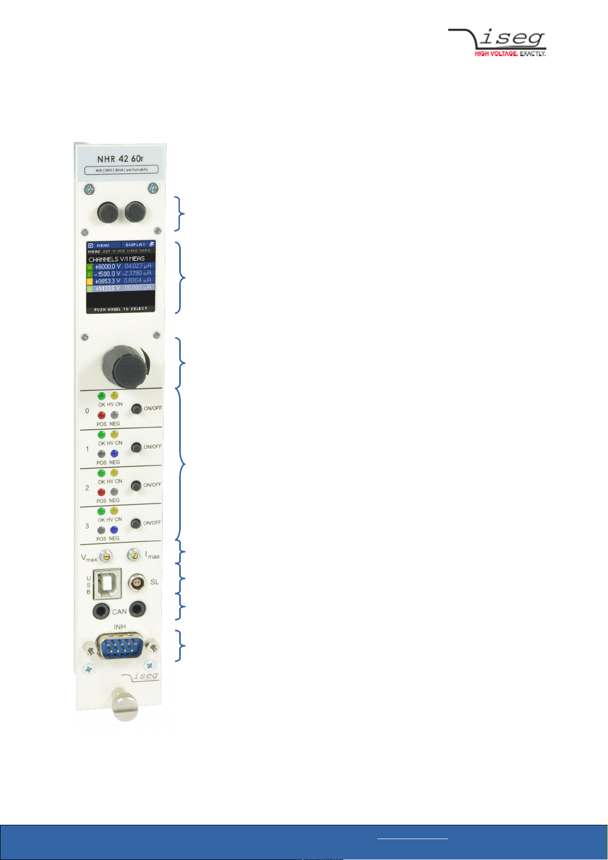
Module status green LED turns on if the channel has the status “Ready”
yellow LED turns on if the channel has the status “HV ON”
HV connector SHV
System connector NIM standard compliant connector
Safety Loop connector Lemo 2pole: FFA.0S. 02.CLAC
Safety Loop socket Lemo 2pole: ERA.0S. 02.CLL
Single channel inhibit connector SUB-D9 male
Protection INHIBIT, Safety loop, short circuit, overload, hardware V/I limits
Case 1/12 NIM standard cassette
Operating temperature 0 – 40 °C
Storage temperature -20 - 60 °C
Table 1: Technical data: Specifications