manuals.online logo
Brands
  1. Home
  2. •
  3. Brands
  4. •
  5. Festo
  6. •
  7. Industrial Equipment
  8. •
  9. Festo MS9-SV C Series User manual

Festo MS9-SV C Series User manual

MS9-SV-...-C
Soft start/quick exhaust valve
Festo SE & Co. KG
Ruiter Straße 82
73734 Esslingen
Deutschland
+49 711 347-0
www.festo.com
Operating instructions
8164018
2022-06a
[8164020]
Translation of the original instructions
© 2022 all rights reserved to Festo SE & Co. KG
1About this document
This document describes the use of the soft start/quick exhaust valve.
The document contains additional information for use of the product in safety-
related systems (safety handbook in accordance with IEC 61508).
1.1 Target group
The document is targeted towards individuals who mount and operate the
product. It is additionally targeted towards individuals who are entrusted with
the planning and application of the product in a safety-oriented system.
1.2 Applicable documents
–Assembly instructions for cover MS6/9-SV-C-MK/MH as tamper protection
All available documents for the product è www.festo.com/sp.
1.3 Specified standards
Version
EN 60204-1:2016-10 EN ISO 13849-2:2012-10
EN ISO 4414:2010-11 EN ISO 14118:2018-02
EN ISO 13849-1:2015-12
Tab. 1: Standards specified in the document
2 Safety
2.1 Safety instructions
–Only use the product in its original condition without unauthorised modifica-
tions.
–Only use the product if it is in perfect technical condition.
–Observe the identifications on the product.
–Take into account the ambient conditions at the location of use.
–Before working on the product, switch off the power supply and secure it
against being switched on again.
–Observe the tightening torques. Unless otherwise specified, the tolerance is
± 20%.
–Only use compressed air as an operating medium in accordance with the speci-
fication è 12 Technical data.
2.2 Intended use
The product is intended for mounting in machines or automation systems and is
only to be used as follows:
–in an industrial environment
–in its original condition, without unauthorised modifications
–in safety-related systems only with cover MS9-SV-MK as tamper protection
–in perfect technical condition
2.3 Foreseeable misuse
Foreseeable misuse includes:
–outdoor operation
–Bypassing of safety functions
–use in reversible operation with reversal of supply air and exhaust air
–use in "Low Demand Mode" according to EN 61511
–vacuum operation
2.4 Training of qualified personnel
Work on the product may only be carried out by qualified personnel who can
evaluate the work and detect dangers. The qualified personnel have skills and
experience in dealing with electropneumatic (open-loop) control technology.
3 Additional information
–Contact the regional Festo contact if you have technical problems
è www.festo.com.
–Accessories è www.festo.com/catalogue.
Designation Type
Silencer U-1-B
Cover, covers the manual override MS9-SV-MH
Cover, covers the adjustment elements for the pressure switching point, the
main flow control and the manual override
MS9-SV-MK
Tab. 2: Accessories
4 Product overview
4.1 Structure
4.1.1 Product design
1
2
3
4
5
6
7
8
9
Fig. 1: Operating elements and
connections
1
Pilot solenoid valve
2
Manual override at the soft-start/quick
exhaust valve
3
Pneumatic port 1 (compressed air
inlet)
4
Pneumatic port 3 (exhaust)
5
Silencer
6
Manual override at the pilot solenoid
valve
7
Flow control screw for setting the
filling time
8
Adjusting screw for setting the pres-
sure switch point
9
Pneumatic port 2 (compressed air
outlet port)
4.1.2 Product variants
The following table lists selected product characteristics and codes that are
necessary for understanding the instruction manual. Complete type code
è www.festo.com/catalogue.
Key features Code Description
Series MS Standard service unit
Size 9 Grid dimension 90 mm
Function -SV Soft-start/quick exhaust valve
Port size -3/4 Thread G 3/4
-1 Thread G 1
-AGD Sub-base G 1/2
-AGE Sub-base G 3/4
-AGF Sub-base G 1
-AGG Sub-base G 1 1/4
-AGH Sub-base G 1 1/2
-N3/4 Thread N 3/4
-N1 Thread N 1
-AQR Sub-base NPT 1/2
-AQS Sub-base NPT 3/4
-AQT Sub-base NPT 1
-AQU Sub-base NPT 1 1/4
-AQV Sub-base NPT 1 1/2
-G Module without connection thread, without sub-base
-NG Module without connection thread, without sub-base (port 3 in
NPT)
Performance Level -C in accordance with EN ISO 13849-1
Supply voltage -V24 24 V DC (plug pattern in accordance with EN 175301-803, type C)
-10V24P 24 V DC (M12 in accordance with IEC 61076-2-101)
-V110 110 V AC (plug pattern in accordance with EN 175301-803,
type C)
-V230 230 V AC (plug pattern in accordance with EN 175301-803,
type C)
Options -S Silencer
Tamper protection -MH Cover - manual override (HHB) only
-MK Cover – pressure switching point (DUP) and main flow control
valve (HD) adjusting screws, manual override (HHB)
Tab. 3: Product variants (selection)
4.2 Function
The MS9-SV-...-C electro-pneumatic pressure soft-start/quick exhaust valve is
intended for rapid pressure reduction and pressurisation in pneumatic line sys-
tems and terminal equipment in industry.
Circuit symbol Function
Soft-start/quick exhaust valve, electro-pneumatically actuated
Tab. 4: Circuit symbol for the function
4.3 Information on functional safety
4.3.1 Achievable safety rating
The product is suitable for use as an element in a safety-related system in accord-
ance with EN ISO 13849-1 up to category 1, performance level (PL) c.
NOTICE
The suitability for certain applications can only be determined in connection with
the assessment of further components of the subsystem. These must achieve the
same safety level.
4.3.2 Safety functions
The safety functions are:
–Exhausting in the downstream piping system and terminals
–Prevention of unexpected start-up (pressurisation)
The safety functions are triggered by switching off the power supply at the pilot
solenoid valve. As long as the voltage at the pilot solenoid valve remains switched
off, the connection between ports 2 and 3 is enabled è 4.2 Function.
This switching position represents the safe state.
4.3.3 Operating conditions
–General information on safe operation è 2 Safety
–Ambient conditions and additional technical specifications è 12 Technical
data.
NOTICE
Actuate the product at least once per month to ensure the safety function works
properly.
4.3.4 Limitations of use
The duration of use is limited to the maximum operating time T10d or is no more
than the mission time TM è 4.3.5 Characteristic values.
4.3.5 Characteristic values
Safety characteristics MS9-SV...-C
Safety function Exhaust
Prevention of unexpected start-up (pressurisation)
Note on forced checking
procedure1)
Switching frequency min. 1/month
Performance level (PL)
in accordance with
EN ISO 13849-1
Exhaust: up to category 1, PL c2)
Service life characteristic B10 0.35 mill. switching cycles
Service life TM [a] 20
Maximum operating time T10d [a] 2 x B10/nop or max. TM
Diagnostic coverage
(Diagnostic Coverage)
DC 0
Hardware fault tolerance
(Hardware Fault Tolerance)
HFT 0
Average probability of dan-
gerous failure per hour
(Average probability of dan-
gerous failure per hour)
PFHdè Fig. 2
Exhaust time [s] è 12.4 Exhaust time
CE marking, Declaration of conformity è www.festo.com/sp
1) Use in "low demand mode" is not permissible.
2) Applies up to the average number of actuations per year = 180,000
Tab. 5: Safety characteristics
Fig. 2: PFHd value, dependent on the average number of operations per year (nop)
5 Assembly
Information about mounting the module connector, connecting plate and
mounting bracket can be found in the instruction manual enclosed with the
relevant accessories.
5.1 Requirements
–Take appropriate measures to remove any particles in the supply lines.
5.2 Preparation
12
Fig. 3: Flow direction
1
Digit 1 for port 1
2
Digit 2 for port 2
–Place product as close as possible to the installation site.
–Place the product so that there is enough space for removing and installing the
silencer.
–Observe the flow direction from port 1 to port 2. The numbers 1 and 2 on the
housing of the MS9-SV-...-C serve as orientation.
5.3 Assembly with MS-series service unit components
WARNING
Loss of the safety function
If devices that impair the exhaust are placed behind the pneumatic connection 2
of the soft start/quick exhaust valve, this can result in loss of the safety function.
•Only place devices that do not impair the exhaust downstream of pneumatic
connection 2.
1 2
Fig. 4: Assembly
1
Seal
2
Module connector
1. Insert a seal 1 between the individual devices (module connector MS9-MV in
scope of delivery).
2. Place the module connector 2 in the slots of the separate devices.
3. Fasten the module connector with two screws (in scope of delivery of module
connector MS9-MV). Maximum tightening torque 1.2 Nm
6 Installation
6.1 Safety
WARNING
Risk of injury from compressed air.
• Before carrying out installation and maintenance work, switch off the com-
pressed air supply.
6.2 Pneumatic installation
Port 1 and 2
If using screw connectors:
ISO 228 NPT
MS9-…-3/4 18.5 mm MS9-…-N3/4 18.5 mm
MS9-…-1 18.5 mm MS9-…-N1 18.5 mm
MS9-…-AGD/AGE/AGF 18.5 mm MS9-…-AQR/AQS/AQT 18.5 mm
MS9-…-AGG/AGH 31.5 mm MS9-…-AQU/AQV 31.5 mm
Tab. 6: Max. screw-in depth
1. Note the permissible screw-in depth of the connector thread.
1.
2. Make sure that the compressed air lines are connected correctly.
3. Screw the fittings into the pneumatic ports using a suitable sealing material.
Port 3, thread size G 1 or NPT 1
Exhausting a system using the MS9-SV-...-C results in high noise levels.
• Recommendation: use silencer è www.festo.com/catalogue.
NOTICE
The U-1-B silencer listed in the accessories can only be retrofitted or replaced on
devices with a metric thread.
If the silencer is retrofitted on a device with an NPT thread at port 3, the cover of
the MS9-SV-...-C may be destroyed. An adequate silencer with NPT thread must be
used for the retrofit.
1. Screw the silencer into pneumatic port 3.
2. Make sure exhaust is unhindered: neither the silencer nor port 3 may be
blocked.
6.3 Electrical installation
MS9-SV-...-C-10V24P/-V24:
WARNING
Risk of injury due to electric shock.
• For the electrical power supply with extra-low voltages, use only PELV circuits
that guarantee a reinforced isolation from the mains network.
•Observe IEC 60204-1/EN 60204-1.
MS9-SV-...-C-V110/-V230:
WARNING
Risk of injury due to electric shock.
• Electrical connections must only be established when the voltage is discon-
nected and by qualified personnel.
•Use only voltage sources in accordance with IEC 60204-1/EN 60204-1.
•Connect the pilot solenoid valve. Accessories è www.festo.com/catalogue.
7Commissioning
7.1 Pressurising the product and piping system
1. Apply operating pressure p1 at MS9-SV-...-C.
2. Switch on supply voltage.
The outlet pressure p2 is built up slowly. The filling time "t" is set via the flow
control screw on the cover è 4.1.1 Product design. The output pressure rises
in accordance with the throttle position è 12.2 Pressurisation flow rate. If the
pre-set pressure switching point (PSP) is reached, the main seat of the valve
opens è 12.3 Pressure switching point (PSP).
ÄThe downstream piping system is pressurised.
If the cover is not mounted as tamper protection, the pressurisation process is
started with the soft-start function by actuation of one of the manual overrides
(è 4.1.1 Product design).
• Reset manual override è 7.3 Resetting the internal manual override.
7.2 Cover for tamper protection
Use:
–In a safety-related system, the setting and control elements must be equipped
with a cover for tamper protection è 3 Additional information.
If the cover is mounted as tamper protection, the manual overrides cannot be
actuated.
–In a non-safety-related system, use of the cover is optional.
7.3 Resetting the internal manual override
A reset will be required if the internal manual override at the soft-start/quick
exhaust valve 3 was previously actuated without the cover as tamper protection
being mounted. Reset can be performed through one of the following measures.
1
2
3
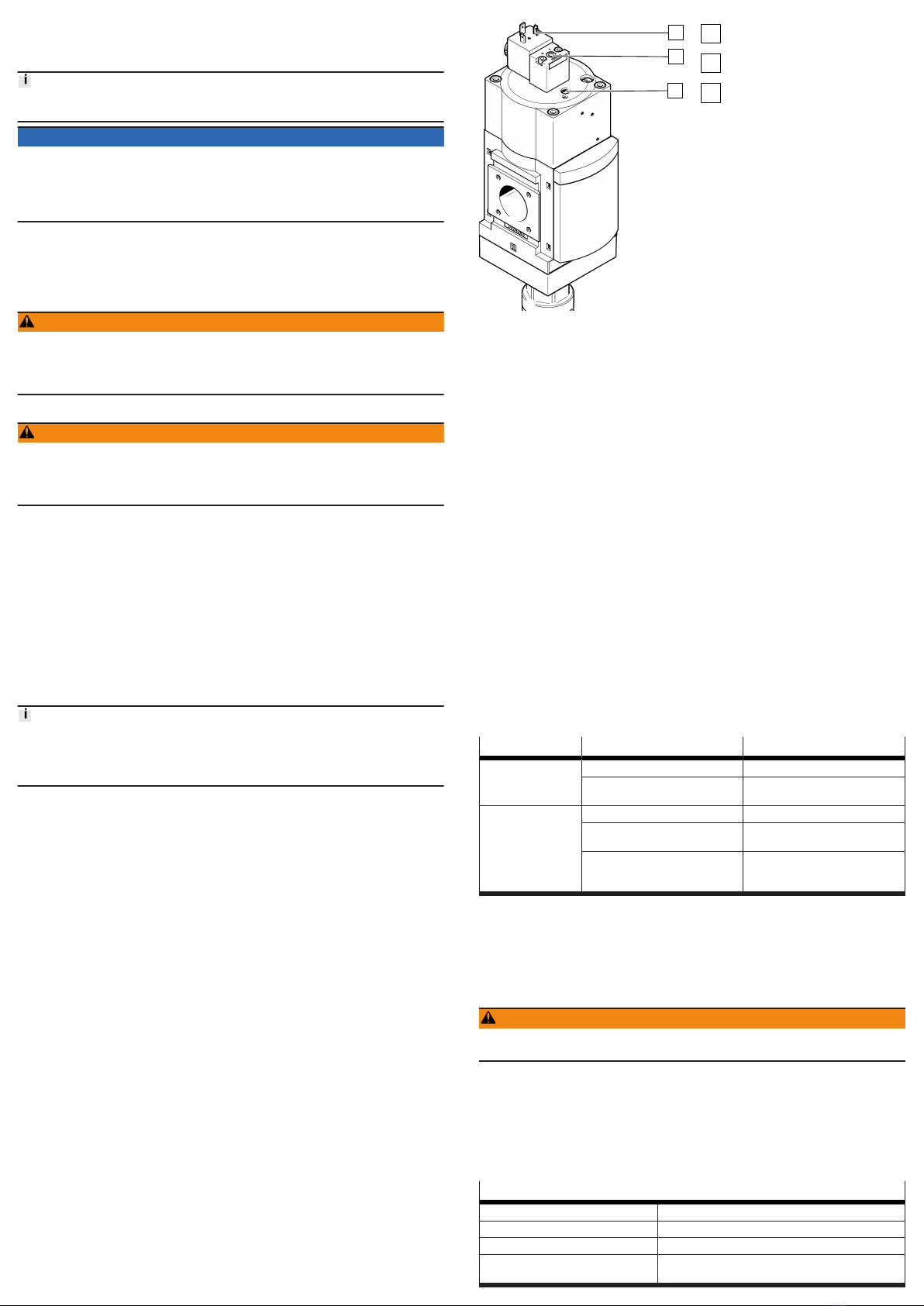
Fig. 5: Reset of the internal manual
override
1
Electrical connection of pilot control
solenoid valve
2
Manual override at the pilot solenoid
valve
3
Manual override at the soft-start/quick
exhaust valve
•Output of an electrical signal to pilot solenoid valve 1.
or
• Actuation of the manual override at the pilot solenoid valve 2.
8 Operating
If the voltage drops, for example because the power supply is switched off, the
product exhausts the downstream piping system è 4.2 Function.
After actuation of the internal manual override:
è 7.3 Resetting the internal manual override
9 Maintenance
9.1 Maintenance work
A dirty silencer can extend the time needed for exhausting the system and thus
restrict the safety function.
•Check the silencer regularly and replace if necessary.
9.2 Cleaning
1. Switch off energy sources:
–Operating voltage
–Compressed air
2. If necessary, clean the product on the outside. Soap suds (max. +50 °C),
petroleum ether and all non-abrasive cleaning agents may be used.
10 Malfunctions
10.1 Fault clearance
Malfunction Cause Remedy
Valve switches
abruptly.
Pressure switching point is too low. –Correct settings.
Main flow control valve (FCV) is
opened too far.
–Correct settings.
Valve does not switch. Pressure switching point is too high. –Correct settings.
Main flow control valve (FCV) is not
opened far enough.
–Correct settings.
Leakage in connected system too
high. The switching pressure is not
reached.
–Reduce leakage in system.
Tab. 7: Fault clearance
Repairs to the product are not permissible.
–In the event of malfunctions or failure: replace the product and let Festo know
about the failure.
–Return defective product to Festo.
11 Dismantling
WARNING
Risk of injury from compressed air.
• Before dismantling work, switch off the compressed air supply.
Switch off energy sources:
–Operating voltage
–Compressed air
2. Disconnect the relevant connections of the MS9-SV-...-C.
12 Technical data
12.1 General data
MS9-SV-...-C
Certificates, declaration of conformity è www.festo.com/sp
Pneumatic port 1 Port sizes è 4.1.2 Product variants
Pneumatic port 2 Port sizes è 4.1.2 Product variants
Pneumatic port 3 –G 1
–NPT 1
MS9-SV-...-C
Type of mounting –In-line installation
–with accessories
Mounting position Any
Design Piston gate valve
Actuation type Electric
Exhaust function Cannot be throttled
Type of control Pilot-controlled
Valve function –3/2-way valve, closed, monostable
–Adjustable soft-start function
Operating medium Compressed air to ISO 8573-1:2010 [7:4:4] and inert
gases
Information on operating
medium
Lubricated operation possible, in which case lubricated
operation will always be required
Operating pressure p1 [MPa] 0.35 … 1.0
-10V24P [bar] 3.5 … 10
[psi] 50.75 … 145
Operating pressure p1 [MPa] 0.35 … 1.6
-V24, -V110, -V230 [bar] 3.5 … 16
[psi] 50.75 … 232
Pressure switching point Adjustable è 12.3 Pressure switching point (PSP)
Pressurisation flow rate Adjustable by flow control valve è 12.4 Exhaust time
Standard nominal flow rate
1 } 2
[l/min] -3/4/-N3/4: 14150
-1/-N1: 14140
-N3/4: 14900
-N1: 14100
-AGD/-AQR: 16500
-AGE/-AQS: 14400
-AGF/-AQT: 13800
-AGG/-AQU: 13200
-AGH/-AQV: 13200
Electrical connection
-10V24P Plug, M12x1, 4-pin
-V24, -V110, -V230 Plug, square design, according to EN 175301-803, type A
Coil characteristics
-10V24P 24 V DC, 2.7 W
-V24 24 V DC, 8.4 W
-V110 110 V AC 50/60 Hz, pick-up power 14.5/12 VA, holding
power 10.5/7.6 VA
-V230 230 V AC, 50/60 Hz, pick-up power 14.5/12 VA, holding
power 10.5/7.6 VA
Permissible voltage fluctua-
tions
[%] 10
Operating and environmental conditions
Ambient temperature [°C] 0 … +60 (0 … +50 with pressure sensor)
Temperature of medium [°C] 0 … +60 (0 … +50 with pressure sensor)
Storage temperature [°C] 0 … +60 (0 … +50 with pressure sensor)
Shock resistance Shock test with severity level 1 in accordance with
FN 942017-5 and EN 60068-2-27
Vibration resistance Transport application test with severity level 1 in accord-
ance with FN 942017-4 and EN 60068-2-6
Sound pressure level [dB(A)] 93
Degree of protection IP65 with plug socket
Weight
without silencer [g] 2970
with silencer [g] 3200
Materials
Housing Die-cast aluminium
Cover Wrought aluminium alloy
Bottom cover PA
Seals NBR
Tab. 8: General technical data
Type of severity level (SL)
Vibration load
Frequency range [Hz] Acceleration [m/s2] Deflection [mm]
SL1 SL2 SL1 SG2 SL1 SL2
2 … 8 2 … 8 – – ±3.5 ±3.5
8 … 27 8 … 27 10 10 – –
27 … 58 27 … 60 – – ±0.15 ±0.35
58 … 160 60 … 160 20 50 – –
160 … 200 160 … 200 10 10 – –
Shock load
Acceleration [m/s2] Duration [ms] Shocks per direction
SL1 SL2 SL1 SL2 SL1 SL2
±150 ±300 11 11 5 5
Type of severity level (SL)
Continuous shock load
Acceleration [m/s2] Duration [ms] Shocks per direction
±150 6 1000
Tab. 9: Type of severity level (SL)
12.2 Pressurisation flow rate
Flow rate qn as a function of the number of revolutions n of the main flow control
valve screw (FCV)
p1 = 1.4 MPa (14 bar; 203 psi)
p1 = 1 MPa (10 bar; 145 psi)
p1 = 0.6 MPa (6 bar; 87 psi)
p1 = 0.3 MPa (3 bar; 43.5 psi)
Fig. 6: Flow rate qn depending on the revolutions n
Range up to 5 revolutions
p1 = 0.3 MPa (3 bar; 43.5 psi)
p1 = 0.6 MPa (6 bar; 87 psi)
p1 = 1 MPa (10 bar; 145 psi)
p1 = 1.4 MPa (14 bar; 203 psi)
Fig. 7: Flow rate qn up to 5 revolutions
12.3 Pressure switching point (PSP)
A slow pressure build-up of outlet pressure p2 is achieved with the main flow
control valve located in the cover. If the output pressure p2 has reached the
switch-through pressure, the valve opens and the complete operating pressure p1
is applied at the output. The pressure switching point (PSP) can be set by turning
the adjusting screw for the pressure switching point.
Maximum PSP
Minimum PSP
0
0.1
0.2
0.3
0.4
0.5
0.6
0.7
0,8
0.9
0.35
0.6
1
1.6
Fig. 8: Pressure switching point
Example:
At an operating pressure p1 = 6 bar, the pressure switching point can be set in a
range from 1.8 ... 5.5 bar.
12.4 Exhaust time
The following table shows the exhaust time in normal operation (N) with silencer
U-1-B at various volumes and operating pressures.
Normal operation N Exhaust time [s]
Operating pres-
sure
[MPa] 0.4 0.6 1 1.6
[bar] 4 6 10 16
[psi] 58 87 145 232
Exhaust to [MPa] 0.1 0.05 0.1 0.05 0.1 0.05 0.1 0.05
[bar] 1.0 0.5 1.0 0.5 1.0 0.5 1.0 0.5
[psi] 14.5 7.25 14.5 7.25 14.5 7.25 14.5 7.25
Volume [l] 10 0.53 0.62 0.65 0.75 0.8 0.9 0.93 1.03
20 0.69 0.89 0.9 1.08 1.13 1.31 1.37 1.56
40 1.17 1.55 1.62 2.02 2.02 2.44 2.56 3.02
150 3.48 4.87 4.66 6.1 6.49 8.11 8.33 10.09
Tab. 10: Exhaust time

Other Festo Industrial Equipment manuals

Festo HGRT Series User manual

Festo

Festo HGRT Series User manual

Festo DG Series Parts list manual

Festo

Festo DG Series Parts list manual

Festo KSK User manual

Festo

Festo KSK User manual

Festo SPC11 Series Operating and installation instructions

Festo

Festo SPC11 Series Operating and installation instructions

Festo DPA-***-10-***-CRVZS Series User manual

Festo

Festo DPA-***-10-***-CRVZS Series User manual

Festo DPA-***-A Series User manual

Festo

Festo DPA-***-A Series User manual

Festo EGC-TB-KF User manual

Festo

Festo EGC-TB-KF User manual

Festo CTEU-VN User manual

Festo

Festo CTEU-VN User manual

Festo OVEL A-RA1 Series User manual

Festo

Festo OVEL A-RA1 Series User manual

Festo FSS-F-12 User manual

Festo

Festo FSS-F-12 User manual

Festo CTEU-EC Operating and installation instructions

Festo

Festo CTEU-EC Operating and installation instructions

Festo SLTE Series User manual

Festo

Festo SLTE Series User manual

Festo DMES Series User manual

Festo

Festo DMES Series User manual

Festo DMES Series User manual

Festo

Festo DMES Series User manual

Festo ELGA-TB-G User manual

Festo

Festo ELGA-TB-G User manual

Festo CPV10-EX-VI User manual

Festo

Festo CPV10-EX-VI User manual

Festo MPS 8059892 Service manual

Festo

Festo MPS 8059892 Service manual

Festo ADN-KP Series Setup guide

Festo

Festo ADN-KP Series Setup guide

Festo 571816 User manual

Festo

Festo 571816 User manual

Festo VTEM User manual

Festo

Festo VTEM User manual

Festo EHPS LK Series User manual

Festo

Festo EHPS LK Series User manual

Festo ELGA-BS-KF-80 User manual

Festo

Festo ELGA-BS-KF-80 User manual

Festo CPX-FB37 User manual

Festo

Festo CPX-FB37 User manual

Festo OVEM-05 User manual

Festo

Festo OVEM-05 User manual

Popular Industrial Equipment manuals by other brands

Eaton P3 Z Series Instruction leaflet

Eaton

Eaton P3 Z Series Instruction leaflet

ABB HT563889 Operation manual

ABB

ABB HT563889 Operation manual

Carpenter MFG. Co., Inc. Compu-Strip 75 Operator's manual

Carpenter MFG. Co., Inc.

Carpenter MFG. Co., Inc. Compu-Strip 75 Operator's manual

MIYAWAKI SV1 user manual

MIYAWAKI

MIYAWAKI SV1 user manual

FLO-DYNAMICS TTCF-9A Quick start instructions

FLO-DYNAMICS

FLO-DYNAMICS TTCF-9A Quick start instructions

Ironwood BR23 user manual

Ironwood

Ironwood BR23 user manual

SMC Networks MGZ Series manual

SMC Networks

SMC Networks MGZ Series manual

DUUN PT280 instruction manual

DUUN

DUUN PT280 instruction manual

Toshiba VN-M1500HE installation manual

Toshiba

Toshiba VN-M1500HE installation manual

Promac JMDT-804516-DRO manual

Promac

Promac JMDT-804516-DRO manual

Enerpac CST271 instruction sheet

Enerpac

Enerpac CST271 instruction sheet

B DUTCH BD700.000043 installation guide

B DUTCH

B DUTCH BD700.000043 installation guide

Toro MH-400SH2 Operator's manual

Toro

Toro MH-400SH2 Operator's manual

SEW-Eurodrive DOP11B System manual

SEW-Eurodrive

SEW-Eurodrive DOP11B System manual

Nabtesco RV RD2 Series Operation manual

Nabtesco

Nabtesco RV RD2 Series Operation manual

Milnor M60SGH01AE manual

Milnor

Milnor M60SGH01AE manual

CRH Leviat Ancon 2000 installation guide

CRH

CRH Leviat Ancon 2000 installation guide

Nexen AIR CHAMP FMCBE 110-14 user manual

Nexen

Nexen AIR CHAMP FMCBE 110-14 user manual

manuals.online logo
manuals.online logoBrands
  • About & Mission
  • Contact us
  • Privacy Policy
  • Terms and Conditions

Copyright 2025 Manuals.Online. All Rights Reserved.