–8 –Copyright © Liberty Pumps, Inc. 2018 All rights reserved. 8337000G
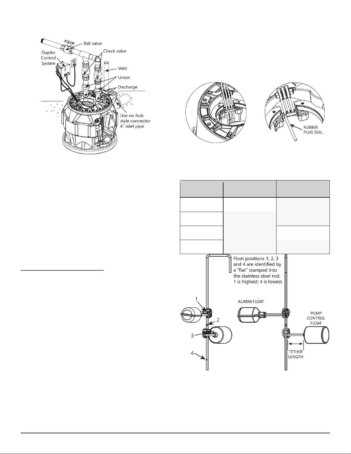
the flat. Tether length is the amount of cord between the clamp
and float.
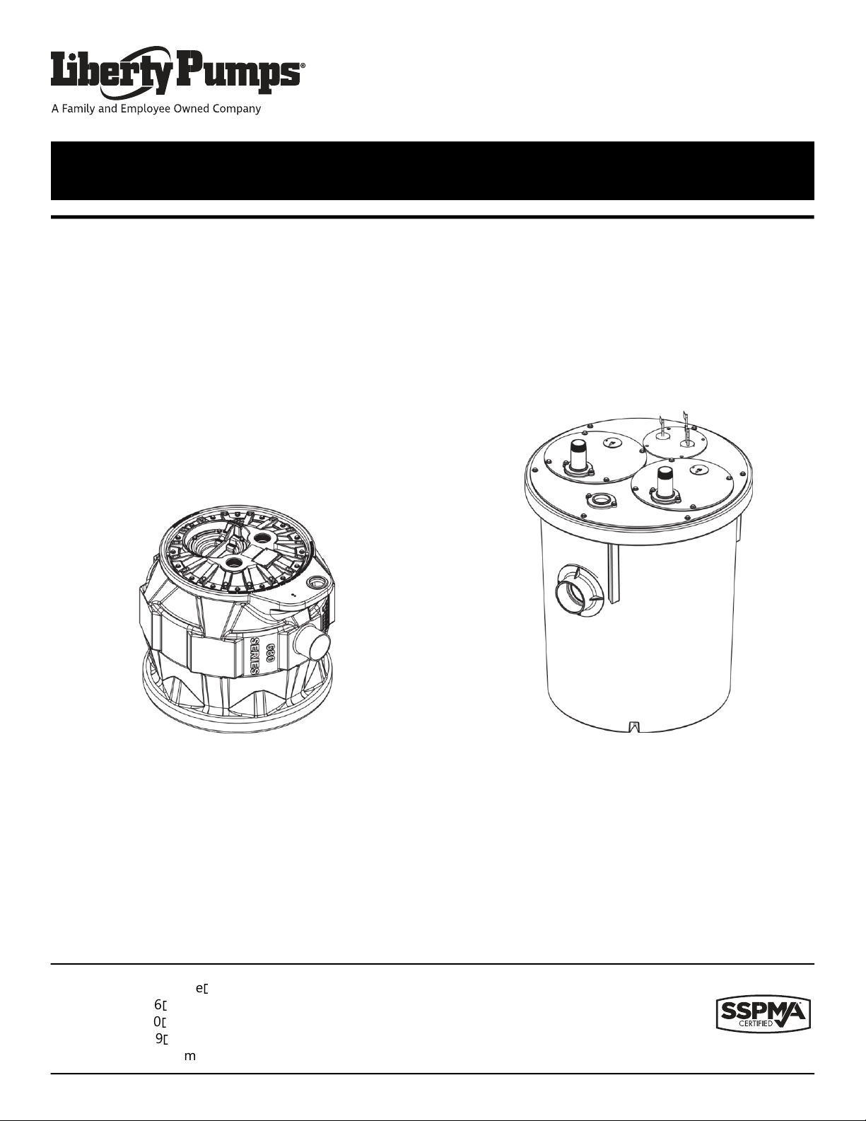
1100-Series Access Cover
The 1100-Series cover contains access to the float and alarm cord
entry/exit seals. Floats are pre-set and system may contain three
or four floats based on selected options.
◼Always disconnect pump(s) from power source(s) before
handling or making any adjustments to either the pump(s),
the pump system, or the control panel.
◼All installation and maintenance of pumps, controls,
protection devices, and general wiring shall be done by
qualified personnel.
◼Do not remove cord and strain relief, and do not connect
conduit to pump.
◼Pump shall be properly grounded using its supplied
grounding conductor. Do not bypass grounding wires or
remove ground prong from attachment plugs. Failure to
properly ground the pump system can cause all metal
portions of the pump and its surroundings to become
energized.
◼Do not handle or unplug the pump with wet hands, when
standing on damp surface, or in water unless wearing
Personal Protective Equipment.
◼Do not lift or carry a pump or a float assembly by its power
cord. This will damage the power cord, and could expose the
electrically live wires inside the power cord.
◼The electrical power supply shall be located within the length
limitations of the pump power cord, and for below grade
installations, it shall be at least 4 ft (1.22 m) above floor level.
◼Protect the power and control cords from the environment.
Unprotected power and control (switch) cords can allow
water to wick through ends into pump or switch housings,
causing surroundings to become energized.
◼Do not use an extension cord to power the product.
Extension cords can overload both the product and
extension cord supply wires. Overloaded wires will get very
hot and can catch on fire.
◼This product requires a separate, properly fused and
grounded branch circuit, sized for the voltage and amperage
requirements of the pump, as noted on the nameplate.
Overloaded branch circuit wires will get very hot and can
catch on fire.
◼Do not use this product with or near flammable or explosive
fluids such as gasoline, fuel oil, kerosene, etc. If rotating
elements inside pump strike any foreign object, sparks may
occur. Sparks could ignite flammable liquids.
◼Sewage and effluent systems produce and may contain
flammable and explosive gases. Prevent introduction of
foreign objects into basin as sparks could ignite these gases.
Use caution using tools and do not use electronic devices or
have live, exposed electrical circuits in or around basins,
open covers and vents.
◼These pumps are not to be installed in locations classified as
hazardous in accordance with the National Electric Code®,
ANSI/NFPA 70.
◼Do not modify the pump/pump system in any way.
Modifications may affect seals, change the electrical loading
of the pump, or damage the pump and its components.
◼All pump/pump system installations shall be in compliance
with all applicable Federal, State, and Local codes and
ordinances.
◼Vent basin in accordance with local code. Proper venting of
sewer gases alleviates poisonous gas buildup and reduces
the risk of explosion and fire from these flammable gases.
◼Wear adequate Personal Protective Equipment when
working on pumps or piping that have been exposed to
wastewater. Sump and sewage pumps often handle
materials which can transmit illness or disease upon contact
with skin and other tissues.
◼Do not remove any tags or labels from the pump or its cord.
◼Keep clear of suction and discharge openings. To prevent
injury, never insert fingers into pump while it is connected to
a power source.
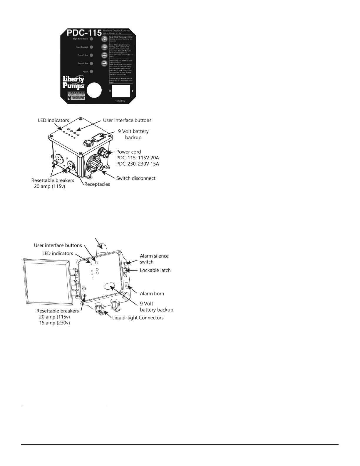
P680-Series System Controller
P680-Series systems are connected to a controller that monitors
the operation of the pumps. The controller will automatically
alternate between the two pumps each cycle to maintain equal
wear. It will also monitor for high water conditions and alarms if
necessary. The controller has visual indicators that show the
operation of the sump as well as operator controls to test
functionality. The controller will also identify a non-functioning
component. For complete operation, refer to the user manual for
the controller.
Liberty Pumps offers both an indoor (Figure 9) and outdoor
(Figure 10) version of the controller.
Note: The cord ends must be removed in order to wire the
outdoor controller.