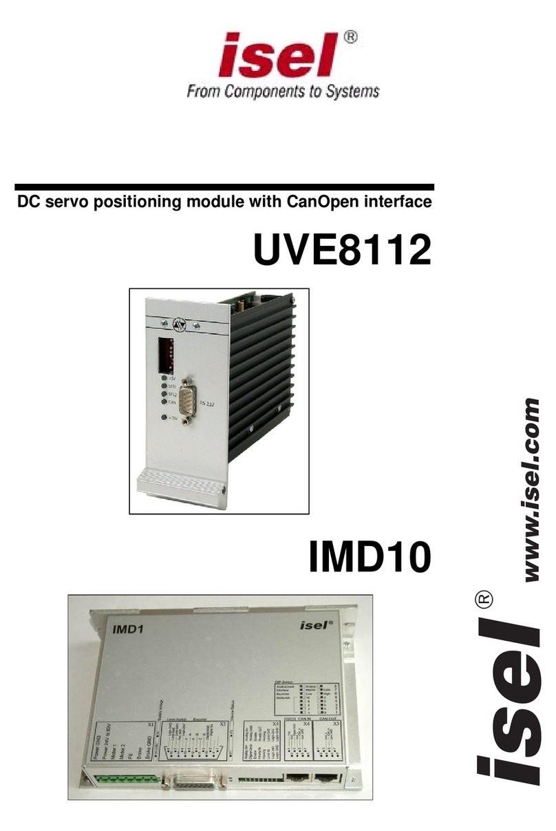
Isel IMD20 User manual

AC servo positioning module with CanOpen interface
IMD20
IMD40
www.isel.com
®

Positioning module IMD20, IMD40
espite t and other errors cannot be excluded.
you have any suggestions for improvements and hints as regards errors, don’t hesitate to contact us.
d,
n safe and EMC-compliant
stallation” starting on page 15.
o not try to install or commission the servo drive controller before carefully reading all safety notes for
lectrical drives and controllers contained in this document. These safety instructions and all other user
otes must be read prior to any work with the servo drive controller.
Tel.: (06659) 981-0
Fax: (06659) 981-776
email:
Remarks concerning this manual:
D the utmost care, prin
If
Company: isel Germany AG © 2009
All rights reserved.
Without the prior written content of isel Germany AG, no part of this publication may be reproduce
stored in a retrieval system or transmitted in any way whatsoever.
No responsibility is accepted for the correctness of the data contained in this manual. Isel Germany AG
company reserves the right to make changes to the contents hereof without prior notice.
Prior to the initial use of the servo drive controller you must read the chapters “Safety notes for
electrical drives and controllers” starting on page 8 and “Notes o
in
D
e
n
Manufacturer: isel Germany AG
Bürgermeister-Ebert-Straße 40
D-36124 Eichenzell
http://www.isel.com
Version: 10/20/2009

Positioning module IMD20, IMD40 Table of contents
Table of contents
Table of contents...........................................................................................3
Overview ........................................................................................................7
Features of the drive module........................................................................................................ 7
Scope of application..................................................................................................................... 7
Safety notes for electrical drives and controllers ......................................8
Used symbols............................................................................................................................... 8
General notes...............................................................................................................................8
Danger resulting from misuse......................................................................................................9
General safety notes...................................................................................................................10
Safety notes for assembly and maintenance...............................................................................11
Protection against contact with electrical parts..........................................................................12
Protection against electrical shock by means of protective extra-low voltage (PELV) .............13
Protection against dangerous movements..................................................................................13
Protection against contact with hot parts ...................................................................................14
Protection during handling and assembly.................................................................................. 14
Notes on safe and EMC-compliant installation.........................................15
Definition and terms ..................................................................................................................15
General information on EMC ....................................................................................................16
EMC-compliant cabling............................................................................................................. 16
Description of the drive module.................................................................18
Settings and status display......................................................................................................... 18
DIP switch...................................................................................................................... 18
Modes of operation.........................................................................................................18
LEDs IMD20.................................................................................................................. 19
LEDs IMD40.................................................................................................................. 20
Hardware description IMD20.................................................................................................... 21
Connectors...................................................................................................................... 21
Frame connector X1 – Connection of the operating voltage 40V-95V, motor and
brake................................................................................................................... 21
Frame connector X2 – 15-pin Sub-D – Connection of the encoder, hall sensors
and limit switch................................................................................................... 22
Frame connector X3 – 20 pin – System connection............................................ 22
Frame connector X4 – RJ45 - RS-232 and CAN IN ...........................................23
Frame connector X5 – RJ45 – CAN OUT .......................................................... 23
Jumper settings............................................................................................................... 23
Wiring of the inputs and outputs ....................................................................................23
Digital Inputs limit switch, Enable ..................................................................... 23
Digital output Ready...........................................................................................24
Digital output Homing........................................................................................24
Digital output Brake........................................................................................... 24
Digital output Limit switch chain ....................................................................... 25
Analogue input....................................................................................................25
Encoder connections........................................................................................... 25
CAN ....................................................................................................................26
Hardware description IMD40.................................................................................................... 27
Connectors...................................................................................................................... 27
Frame connector X1 – Connection of the operating voltage AC 220V, motor and
brake................................................................................................................... 27
Frame connector X2 –Connection of operating voltage 24V, temperature and
brake................................................................................................................... 28
3

Table of contents Positioning module IMD20, IMD40
Frame connector X3 – 15-pin Sub-D - Connection encoder, hall sensors, limit
switch..................................................................................................................28
Frame connector X4 – 20-pin – System connection............................................29
Frame connector X5 – RJ45 - RS-232 und CAN IN............................................29
Frame connector X6 – RJ45 – CAN OUT...........................................................29
Frame connector X7 – Brake resistor................................................................30
Jumper settings ...............................................................................................................30
Wiring of the inputs and outputs.....................................................................................31
Digital inputs limit switches, reference switch, enable.......................................31
Digital output Ready...........................................................................................31
Digital output Homing........................................................................................31
Digital output Brake ...........................................................................................31
Digital output Limit switch chain........................................................................32
Analogue input....................................................................................................32
Encoder connections...........................................................................................33
CAN ....................................................................................................................33
Data transfer...............................................................................................................................34
Commissioning ..........................................................................................................................36
Overview ........................................................................................................................36
Particularities as regards the commissioning of a gantry axis ........................................36
Examples for the motion control.....................................................................................36
Example 1:..........................................................................................................36
Example 2:..........................................................................................................37
Example 3:..........................................................................................................39
Fault states .................................................................................................................................40
ACSetup programme..................................................................................41
Menus.........................................................................................................................................41
Commands of the File menu...........................................................................................41
The New command (File menu)..........................................................................41
The Open command (File menu).........................................................................41
The Save command (File menu)..........................................................................41
The Save As command (File menu).....................................................................41
The 1, 2, 3, 4 commands (File menu)..................................................................41
The Exit command (File menu)...........................................................................41
Commands of the Connection menu...............................................................................42
The Online Mode On/Off command....................................................................42
The Active Connection / CAN command.............................................................42
The Active Connection / RS232 command..........................................................42
The RS232 Settings command.............................................................................42
The CAN Settings command................................................................................42
Commands of the Commissioning menu........................................................................43
The Step-by-Step Commissioning command.......................................................43
The Random Order command.............................................................................43
The Reset command ............................................................................................43
Commands of the Settings menu ....................................................................................43
The Object Directory command..........................................................................43
Commands of the Extra menu.........................................................................................43
The Extended Functions command.....................................................................43
Password.............................................................................................................43
The Firmware Update / Normal command.........................................................44
The Firmware Update / via Bootstrap Loader command ...................................44
Commands of the View menu.........................................................................................45
The Tool Bar command.......................................................................................45
The Status Bar command....................................................................................45
The Serial Interface command............................................................................45
The CAN Monitor command...............................................................................45
The Drive Status command.................................................................................45
The Language command.................................................................................................45
Commands of the ? menu ...............................................................................................45

Positioning module IMD20, IMD40 Table of contents
The Help Topics command ................................................................................. 45
The Info command.............................................................................................. 45
Programme user interface..........................................................................................................46
Tool bar .......................................................................................................................... 46
Status bar........................................................................................................................ 46
Drive status..................................................................................................................... 47
Monitor window for serial interface...............................................................................47
Monitor window for CAN communication ....................................................................48
Programme functions................................................................................................................. 49
Create a data connection................................................................................................. 49
Offline operation.................................................................................................49
Online operation................................................................................................. 49
Choose Active Connection.................................................................................. 49
RS-232 settings ...................................................................................................49
CAN settings....................................................................................................... 50
Commissioning / Adjustment of parameters...................................................................51
Step-by-step commissioning................................................................................51
Random order.....................................................................................................51
Connection dialogue box.................................................................................... 53
Mode of Operation dialogue box........................................................................54
Offset Calibration dialogue box ......................................................................... 55
Analogue Input dialogue box.............................................................................. 56
Brake dialogue box............................................................................................. 57
Current Controller dialogue box........................................................................58
Encoder dialogue box.........................................................................................60
Motor and Transmission dialogue box............................................................... 61
Velocity Controller dialogue box........................................................................ 63
Direction dialogue box.......................................................................................66
Acceleration dialogue box.................................................................................. 67
Velocity dialogue box ......................................................................................... 68
Position Controller dialogue box .......................................................................69
Can Interpolation dialogue box.......................................................................... 72
Inputs dialogue box ............................................................................................ 74
Reference Run dialogue box............................................................................... 75
Object Directory dialogue box........................................................................................ 76
Firmware update............................................................................................................. 78
CanOpen protocol.......................................................................................79
Overview....................................................................................................................................79
SDO ...........................................................................................................................................81
PDO ...........................................................................................................................................83
Mapping..........................................................................................................................83
Types of transfer............................................................................................................. 84
SYNC......................................................................................................................................... 85
EMCY........................................................................................................................................ 86
Network management - NMT.................................................................................................... 86
Status diagram................................................................................................................ 87
Boot-Up object ...............................................................................................................88
Monitoring – Guarding...................................................................................................88
Object Directory ........................................................................................................................ 90
Communications parameter............................................................................................90
General communications parameters................................................................. 90
PDO / Mapping parameters ............................................................................... 94
Device profile parameters............................................................................................... 99
Device control.....................................................................................................99
Mode of operation ............................................................................................ 101
Current control................................................................................................. 102
Profile Position Mode – position control with ramp profile............................. 105
Interpolated Position Mode – Position control with interpolation................... 107
Homing Mode – Reference run......................................................................... 109
5

Table of contents Positioning module IMD20, IMD40
Moving the axis out of a limit switch ................................................................111
Factor Group – Conversion factors..................................................................111
General parameters..........................................................................................113
Manufacturer-specific parameters ................................................................................120
EDS / DCF files .......................................................................................................................128
Appendix ...................................................................................................129
Connection of Motionking EC motor to the IMD20, IMD40..................................................129
Encoder connection.......................................................................................................129
Motor connection..........................................................................................................130
IMD20 basis connection...............................................................................................131
IMD20 system connection............................................................................................132
Glossary .................................................................................................... 133
Index ..........................................................................................................134

Positioning module IMD20, IMD40 Overview
Overview
The present manual contains all descriptions and documentations required for the wiring,
commissioning and control of the drive module.
It is intended for qualified personnel with basic knowledge of the control and automation technology
as well as of the CAN field bus.
Prior to the initial use of the servo drive controller you must read the chapters “Safety notes for
electrical drives and controllers” starting on page 8 and “Notes on safe and EMC-compliant
installation” starting on page 15.
Do not try to install or commission the servo drive controller before carefully reading all safety notes
for electrical drives and controllers contained in this document. These safety instructions and all other
user notes must be read prior to any work with the servo drive controller.
The basics of the CanOpen protocol are described in a separate chapter to the extent that they are
important to the drive process. This chapter also presents an overview of all CanOpen objects of this
module as well as a description of the drive functions.
The chapter “ACSetup programme” gives a description of the ACSetup programme and serves as a
guide to the commissioning of the drive.
The content of this manual is also provided as online help together with the setting programme.
Features of the drive module
• Supply voltage IMD20 40-95 V DC, IMD40 220 V AC
• Motor current IMD20 bis 25 A (continuous current 12 A), IMD40 bis 13 A
• CAN bus interface according to CanOpen DS301 V4.0 and DS402 V1.0
• RS232 interface
zAnalogue input (±10 V) mit 11-bit resolution
• Inputs for limit and reference switches
• Digital current, velocity and position control with high cycle times
• Brake control
• Gantry operation or synchronous control of 2 modules
• Monitoring of the motor current and encoder signals
• Monitoring of the software through the internal watchdog timer
• Galvanic isolation of processor, power section and I/Os
• Easy firmware update via RS232
Scope of application
The drive module is suited ideally for the control of small- and medium-power permanet magnet
motors. What has to be pointed out is the high torque even at small velocities and the outraging
synchronous characteristics even at low speeds. Thanks to five modes of operation and a high
diversity of adjustable parameters, a broad spectrum of the most diverse applications in the
automation technology and the mechanical engineering can be covered.
The CanOpen interface is an open interface which allows to build up a flexible, extensible plant
structure or to integrate the modules into existing plants.
7

Safety notes for electrical drives and controllers Positioning module IMD20, IMD40
Safety notes for electrical drives and controllers
Used symbols
Information
Important information and notes
Caution !
Nonobservance may result in severe property damages.
DANGER !
Nonobservance may result in property damages and in personal injuries.
Caution! Dangerous voltages.
The safety note indicates a possible perilous voltage.
General note
In the case of d
AG will assu e
s
amage resulting from non-compliance of the safety notes in this manual isel Germany
no liability.m
Prior to the initial use you must read the chapters “Safety notes for electrical drives
and controllers” starting on page 8 and “Notes on safe and EMC-compliant
installation” starting on page 15.
If
ythe documentation in the language at hand is not understood accurately, please contact and inform
our supplier. o drive controller requires proper and professional
A
in th
suffi he product
w
l
truction concerning the standards and accident prevention regulations for the
horisation to switch devices/systems on and off and to ground them as per the
standards of safety engineering and to efficiently label them as per the job demands.
Sound and safe operation of the serv
transportation, storage, assembly and installation as well as proper operation and maintenance. Only
trained and qualified personnel may handle electrical devices:
TR INED AND QUALIFIED PERSONNEL
e sense of this product manual or the safety notes on the product itself are persons who are
ciently familiar with the project, the setup, assembly, commissioning and operation of t
as ell as all warnings and precautions as per the instructions in this manual and who are sufficiently
qua ified in their field of expertise:
• Education and ins
application, or aut
8

Positioning module IMD20, IMD40 Safety notes for electrical drives and controllers
• Education and instruction as per the standards of safety engineering regarding the maintenance
and use of adequate safety equipment.
First aid training.
The follow f the system to prevent personal
injuries and
•
ing notes must be read prior to the initial operation o
/or property damages:
These safety notes must be complied with at all times.
Do not try to install or commission the servo drive controller before carefully reading all
safety notes for electrical drives and controllers contained in this document. These safety
instructions and all other user notes must be read prior to any work with the servo drive
controller.
In case you do not have any user notes for the servo drive controller, please contact your
n
responsible for the safe operation of the servo drive controller.
sales representative. Immediately demand these documents to be sent to the perso
If you sell, rent and/or otherwise make this device available to others, these safety notes
must also be included.
The user must not open the servo drive controller for safety and warranty reasons.
Pro
drive co er!
fessional control process design is a prerequisite for sound functioning of the servo
ntroll
DANGER!
Inappropriate handling of the servo drive controller and non-compliance of the
warnings as well as inappropriate intervention in the safety features may result
in property damage, personal injuries, electric shock or in extreme cases even
death.
Danger resulting from misuse
DANGER!
High electrical voltages and high load currents!
Danger to life or serious personal injury from electrical shock!
DANGER!
High electrical voltage caused by wrong connections!
Danger to life or serious personal injury from electrical shock!
9

Safety notes for electrical drives and controllers Positioning module IMD20, IMD40
DANGER!
Surfaces of device housing may be hot!
Risk of injury! Risk of burning!
DANGER!
Dangerous movements!
Danger to life, serious personal injury or property damage due to unintentional
movements of the motors!
General saf
ety notes
The servo drive controller corresponds to IP20 class of protection as well as pollution
level 1. Make sure that the environment corresponds to this class of protection and
pollution level.
Only use replacements parts and accessories approved by the manufacturer.
The devices must be connected to the mains supply as per EN regulations, so that they
can be cut off the mains supply by means of corresponding separation devices (e.g.
main switch, contactor, power switch).
The servo drive controller may be protected using an AC/DC sensitive 300mA fault
current protection switch (RCD = Residual Current protective Device).
Gold contacts or contacts with a high contact pressure should be used to switch the
con .trol contacts
Pre
conventive interference rejection measures should be taken for control panels, such as
necting contactors and relays using RC elements or diodes.
The safety rules and regulations of the country in which the device will be operated must
be complied with.
The environment conditions defined in the product documentation
critical applications are not allowed must be kept. Safety-
For notes on installation corresponding to EMC, please refer to chapter “Notes on safe
e limits required by
machine or system.
and EMC-compliant installation” (page15). The compliance with th
national regulations is the responsibility of the manufacturer of the
The technical data and the connection and installation conditions for the servo drive
controller are to be found in this product manual and must be met.
10

Positioning module IMD20, IMD40 Safety notes for electrical drives and controllers
DANGER!
The general setup and safety regulations for work on power installations (e.g. DIN,
VDE, EN, IEC or other national and international regulations) must be complied with.
Non-compliance may result in death, personal injury or serious property damages.
Without claiming completeness, the following regulations and others or standards apply:
VDE 0100 Regulations for the installation of high voltage (up to 1000 V) devices
chines
EN 50178 Electronic equipment for use in power installations
les for risk assessment
EN 7 art-up
EN 954- s
EN 60204-1 Electrical equipment of ma
EN ISO 12100 Safety of machinery - Basic terminology, general principles for design
EN 1050 Safety of machinery - Princip
103 Safety of machinery - Prevention of unexpected st
1 Safety-related parts of control system
Safety note
The appro cal safety regulations
and rules f e
plant engine
s for assembly and maintenance
iate DIN, VDE, EN and IEC regulations as well as all national and lopr
or the prevention of accidents apply for the assembly and maintenance of the system. Th
er or the operator is responsible for compliance with these regulations:
The ser y be operated, maintained and/or repaired by
personnel trained and qualified for working on or with electrical devices.
vo drive controller must onl
P evention
r of accidents, injuries and/or damages:
Additionally secure vertical axes against falling down or lowering after the motor has
been switched off, e.g. by means of:
• Mechanical locking of the vertical axle,
• External braking, catching or clamping devices or
• Sufficient balancing of the axle.
The motor holding brake supplied by default or an external motor holding brake driven
by the drive controller alone is not suitable for personal protection!
Render the electrical equipment voltage-free using the main switch and protect it from
being switched on again until the DC bus circuit is discharged, in the case of:
• Maintenance and repair work
• Cleaning
• Long machine shutdowns
Prior to carrying out maintenance work make sure that the power supply has been
turned off, locked and the DC bus circuit is discharged.
The external or internal brake resistor carries dangerous DC bus voltages during
operation of the servo drive controller and up to 5 minutes thereafter. Contact may result
in death or serious personal injury. Actual value of the DC bus voltages see CAN object
0x2072.
11

Safety notes for electrical drives and controllers Positioning module IMD20, IMD40
Be careful during the assembly. During the assembly and also later during operation of
the drive, make sure to prevent drill chips, metal dust or assembly parts (screws, nuts,
cable sections) from falling into the device.
Also make sure that the external power supply of the controller (24V) is switched off.
The DC bus circuit or the mains supply must always be switched off prior to switching off
the 24V controller supply.
Carry out work in the machine area only, if AC and/or DC supplies are switched off.
Sw tput stages or controller enablings are no suitable means of locking. In
the e drive may accidentally be put into action.
itched off ou
case of a malfunction th
e.g. due to the wrong direction of rotation.
Initial operation must be carried out with idle motors, to prevent mechanical damages
Electronic devices are never fail-safe. It is the user’s responsibility, in the case an
electrical device fails, to make sure the system is transferred into a secure state.
The servo drive controller and in particular the brake resistor, externally or internally, can
assume high temperatures, which may cause serious burns.
Protection against contact with electrical parts
This section t
with parts ca an 50 V can be dangerous for people and may cause electrical
shock. Du ng operation of electrical devices some parts of these devices will inevitably carry
dangerous v
only concerns devices and drive components carrying voltages exceeding 50 V. Contac
rrying voltages of more th
rioltages.
DANGER!
High electrical voltage!
Danger to life, danger due to electrical shock or serious personal injury!
The appropr ulations
and rules fo . The
plant engine
iate DIN, VDE, EN and IEC regulations as well as all national and local safety reg
r the prevention of accidents apply for the assembly and maintenance of the system
er or the operator is responsible for compliance with these regulations:
Before switching on the device, install the appropriate covers and protections agains
accidental contact. Rack-mounted devices must be protected against accidental contac
by means of a housing, e.g. a switch cabinet. The regulations VGB4 must be complie
t
t
d
with!
Always connect the ground conductor of the electrical equipment and devices securely
to the mains supply. Due to the integrated line filter the leakage current exceeds 3.5 mA!
12

Positioning module IMD20, IMD40 Safety notes for electrical drives and controllers
Comply with the minimum copper cross-section for the ground conductor over its entire
length as per EN60617!
Prior to the initial operation, even for short measuring or testing purposes, always
connect
cause electrical shock.
the ground conductor of all electrical devices as per the terminal diagram or
ound wire. Otherwise the housing may carry high voltages which canconnect it to the gr
Do not touch electrical connections of the components when switched on.
Prio eeding 50 Volts, disconnect the
device from the mains or power supply. Protect it from being switched on again.
r to accessing electrical parts carrying voltages exc
dimensioning and corresponding short-circuit protection.
For the installation the amount of DC bus voltage must be considered, particularly
regarding insulation and protective measures. Ensure proper grounding, wire
The servo drive controllers can carry voltage until up to 5 minutes a
off (residual capacitor charge). Actual value of D
fter being switched
C bus voltage see object 0x2072
Protection against electrical shock by means of protective extra-low
volta
A voltages between 5 and 50 Volts at the servo drive controller are
p e safe from contact in correspondence with the
fo
untries within the EU: EN 50178/1998, section 5.2.8.1.
ge (PELV)
ll connections and terminals with
rot ctive extra-low voltage, which are designed
llowing standards:
International: IEC 60364-4-41
European co
DANGER!
High electrical voltages due to wrong connections!
Danger to life, risk of injury due to electrical shock!
Only devices an nd wires with a protective extra low voltage (PELV) may be
connected to co
nly connect voltages and circuits with protection against dangerous voltages. Such protection may
Pro
• Improper or faulty wiring or cabling
• Error in sensor or transducer
d electrical components a
nnectors and terminals with voltages between 0 to 50 Volts.
O
be achieved by means of isolation transformers, safe optocouplers or battery operation.
tection against dangerous movements
Dangerous movements can be caused by faulty control of connected motors, for different reasons:
• Error in handling of components
13

Safety notes for electrical drives and controllers Positioning module IMD20, IMD40
• Defective or non-EMC-compliant components
• Error in software in superordinated control system
These errors c ng on the device or after an indeterminate time of
operation.
The monitors in the drive components for the most part rule out malfunctions in the connected drives.
view of personal protection, particularly the danger of personal injury and/or property damage, this
m y not be ements
must be tak erating
state..
an occur directly after switchi
Ina relied on exclusively. Until the built-in monitors come into effect, faulty drive mov
en into account; their magnitude depends on the type of control and on the op
DANGER!
Dangerous movements!
Danger to life, risk of injury, serious personal injuries or property damage!
For the reasons mentioned above, personal protection must be ensured by means of monitoring or
uperordinated measures on the device. These are installed in accordance with the specific data of
e system and a danger and error analysis by the manufacturer. The safety regulations applying to
the system are also taken into consideration. Random movements or other malfunctions may be
caused by switc tallations off, by bypassing them or by not activating them.
Protection ag
s
th
hing the safety ins
ainst contact with hot parts
DANGER!
Housing surfaces may be hot!
Risk of injury! Risk of burning!
Do not touch housing surfaces in the vicinity of heat sources! Danger of burning!
Before accessing devices let them cool down for 10 minutes after switching them off.
Touching hot parts of the equipment such as the housing, which contain heat sinks a
resistors, may cause burns! nd
Protection during handling and assembly
Handling and assembly of certain parts and components in an unsuitable manner may under adverse
conditions c
ause injuries.
14

Positioning module IMD20, IMD40 Notes on safe and EMC-compliant installation
DANGER!
Risk of injury due to improper handling!
Personal injury due to pinching, shearing, cutting, crushing!
Th o
e f llowing general safety notes apply:
Comply with the general setup and safety regulations on handling and assembly.
Use suitable assembly and transportation devices.
Prevent incarcerations and contusions by means of suitable protective measures.
Use suitable tools only. If specified, use special tools.
Use lifting devices and tools appropriately.
If necessary, use suitable protective equipment (e.g. goggles, protective footwear,
protective gloves).
Do not stand underneath hanging loads.
Re ing liquids on the floor immediately to prevent slipping.move leak
Notes on safe and EMC-compliant installation
es the following
Definition and terms
Electromagnetic compatibility (EMC) or electromagnetic interference (EMI) includ
requirements:
• Sufficient immunity of an electrical installation or an electrical device against outside
electrical, magnetic or electromagnetic interferences via cables or the ambient.
15

Notes on safe and EMC-compliant installation Positioning module IMD20, IMD40
• Sufficiently small unwanted emission of electrical, magnetic or electromagnetic interference
from an electrical installation or an electrical device to other devices in the vicinity via cables or
the ambient.
Gen
The
conc following components:
•
•
•
•
In o
posi omprises mains filters, so that it can be operated without additional
shielding and filtering devices.
eral information on EMC
interference emission and interference immunity of a device always depend on the entire drive
ept consisting of the
• Voltage supply
• Servo positioning controller
Motor
Electromechanics
Executiion and type of wiring
Superimposed control
rder to increase interference immunity and to decrease interference emissions the servo
tioning controller already c
In most cases no external filtering is required (see below).
Warning!
This product can cause high-frequency interference in residential areas, which could
require measures for radio interference suppression.
EMC-compliant cabling
The following must be considered for an EMC-compliant setup of the drive system:
• In order to keep the leakage currents and the losses in the motor connection cable as small as
possible, the servo positioning controller should be located as close to the motor as possible.
• Motor cable and angle encoder cable must be shielded.
• The shield of the motor cable is connected to the housing of the servo positioning controller. The
cable shield also has to be connected to the associated servo positioning controller so that the
leakage currents can flow back into the controller causing the leakage.
• The mains-end PE connection and the inner PE conductor of the motor is connected to the PE
connection point of the supply connection
• The signal lines must be as far away from the power cables as possible. They should not be
placed parallel. If intersections cannot be avoided, they should be perpendicular (i.e. at a 90°
angle), if possible.
16

Positioning module IMD20, IMD40 Notes on safe and EMC-compliant installation
• Unshielded signal and control lines should not be used. If t
least be twisted. heir use is inevitable they should at
• Even shielded cables will inevitably have short unshielded ends (unless shielded connector
e following applies:
corresponding pins of the connectors; Maximum length 40
- Connect the total shield on the motor side plane to the connector housing or motor housing;
um length 40 mm.
housings are used). In general, th
- Connect the inner shields to the
mm.
- Length of the unshielded cores 35 mm maximum.
- Connect the total shield on the controller side plane to the PE terminal; Maximum length 40
mm.
Maxim
DANGER!
For safety reasons, all PE ground conductors must be connected prior to initial
operation.
The EN 50178 regulations for protective earthing must be complied with during
installation!
17

Description of the drive module Positioning module IMD20, IMD40
De
Set 20) of the module, a DIP switch is provided for settings
bridge and CAN terminator. Furthermore, LEDs
DIP switch
T s only queried, when the n or after it was reset. During the
operation, a commutation of the switch does whatsoever.
•up the CanOpen node address. Possible node addresses
set, the drive module is started in the operation mode
put”. Comunic via serial interface.
•The switch S5 defines the baud te for n and the RS232 interface. In High
Speed Submode the CAN baud rate of the object Can Baud Rate
(2001) (see object directory, manufac t Can Baud Rate). Under
„Setting->Object directory->Man acture te->03 New High
Speed Submode“ of ACSetup you can c he module (double click on
the object). After switch off and switch s used. When you
change the baud rate of the module do nd
interpola aud rate of 250 kBit/s is needed, for
mal interpolation you need at least 125 kBit/s. Default is 1 Mbit/s..
In the state ON the switch S7 connects the both connectors Limit switch chain In and Limit switch
chain Out.
S8 terminates the CAN bus with a resistor of 120 Ohm.
scription of the drive module
tings and status display
On the front (IMD40) or on the side (IMD
concerning the node address, the baud rate, limit
show the current mode of operation.
he DIP switch i module is switched o
not have any effects
The switches S1 to S4 are u
are: 1to 15. If the Node
“velocity controller anlog in
sed to set
number 0 is ation is only possible
ra the CAN connectio
the module is determined by
turer specific objects, objec
uf r specific objects->2001 Can Baud Ra
hange the CAN baud rate of t
on of the modul the new baud rate i
not forget to change also the baud rate in ACSetup a
CANSet. For the tion with gantry axis at least a b
nor
•
• In the state ON the switch
12345678
NodeAddress
E.g. 1
Baud Rate
01
RS-232: 57,6 kBd
CAN: High Speed Submode
RS-232: 19,2 kBd
CAN: 20 kBit/s
RS-232 / CAN CAN RS-232
Limit Bridge OFF
ON
OFF
ON
CAN-Terminator
Modes of operation
Here, two groups of modes of operation are available differing from each other mainly in the type of
the controller release. In case of the CanOpen modes of operation, the internal state (state machine)
18

Positioning module IMD20, IMD40 Description of the drive module
is controlled via the Can bus or the serial interface, while there are only two states for the other
modes of operation (Enabled, Disabled) which are linked directly with the enabling signal (Input 4).
The active mode of operation of the drive module is defined through the settings of the DIP switch on
the front side and through the “Modes of operation” parameter ("Modes of Operation", 6060h).
See “Mode of operation” on page 101 .
When the module is switched on, the DIP switch is queried at first. If the node address is set to 0 at
the DIP switch the operation mode “velocity controller analogue input” is set. If the node address is
unequal 0 the parameter „modes of operation“ is evaluated.
Node address Mode of operation
Modes of
operation
1 Profile position mode
3 Profile velocity mode
6 Reference run (homing mode)
7 Interpolation (interpolated position mode)
-2 Velocity control, analogue input
Node addr
Mode of opess unequal 0.
eration is set by
the parameter „Modes of
operation“
-3 Moving the axis away from a limit switch
Node address equal 0 Velocity control, analogue input
LED
s IMD20
1
+5V
11
+40-95V
1
STS1
Via the LEDs on the front, it is possible to indicate the existence of the two main supply voltages.
Furthermore, the current state of the module can be viewed here (STS1 and STS2).
In case of a fault (Fault state), the two-digit error code of the current fault is given via a blinking code.
1st digit: number of blinking impulses of both status LEDs (STS1 und STS2).
2nd digit: number of blink impulses of LED STS2.
See "EMCY" on page 86 for the description of the error code.
19

Description of the drive module Positioning module IMD20, IMD40
+5V
40-95V
Drive status
Everything is in order
STS1
Blinking code in case of fault
Blinking interval about 0,5s
(No permanent simultaneous blinking)
No enabling signal (input 4)
Blinking interval about 1,5s
(permanent simultaneous blinking)
STS2
NMT status: STOPPED or
PRE-OPERATIONAL
Disturbance on the CAN bus
LEDs IMD40
STS2 220V
STS1
AC
+5V
Via th EDs on the fr ossible to indicate the existence of the two main supply voltages.
Furthe ore, the dule can be viewed here (STS1 and STS2).
case of a fault (Fault state), the two-digit error code of the current fault is given via a blinking code.
1st digit: number of blinking impulses of both status LEDs (STS1 und STS2).
2nd digit: number of blink impulses of LED STS2.
See "EMCY" on page 86 for the description of the error code.
In case of a missing enabling signal, all two LEDs (STS1, STS2) blink about once every 1.5 seconds.
e L ont, it is p
rm current state of the mo
In
+5V
40-95V
Drive status
Everything is in order
Blinking code in case of fault
Blinking interval about 0,5s
(No permanent simultaneous blinking)
No enabling signal (input 4)
Blinking interval about 1,5s
(permanent simultaneous blinking)
STS1
STS2
NMT status: STOPPED or
PRE-OPERATIONAL
Disturbance on the CAN bus
20
This manual suits for next models
1
Table of contents
Other Isel Control Unit manuals
Popular Control Unit manuals by other brands

Vaillant
Vaillant Mixer module VR 61 OPERATING AND INSTALLATION Manual

SLV
SLV 470820 Quick installation guide

Moog
Moog D661K Series operating instructions

SMC Networks
SMC Networks VM200-A Series Operation manual

Quectel
Quectel QuecOpen AG525R-GL Hardware design

Emerson
Emerson 8323G0 Series Installation & maintenance instructions