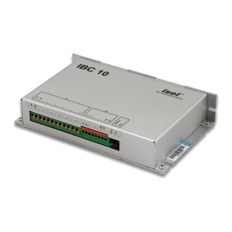
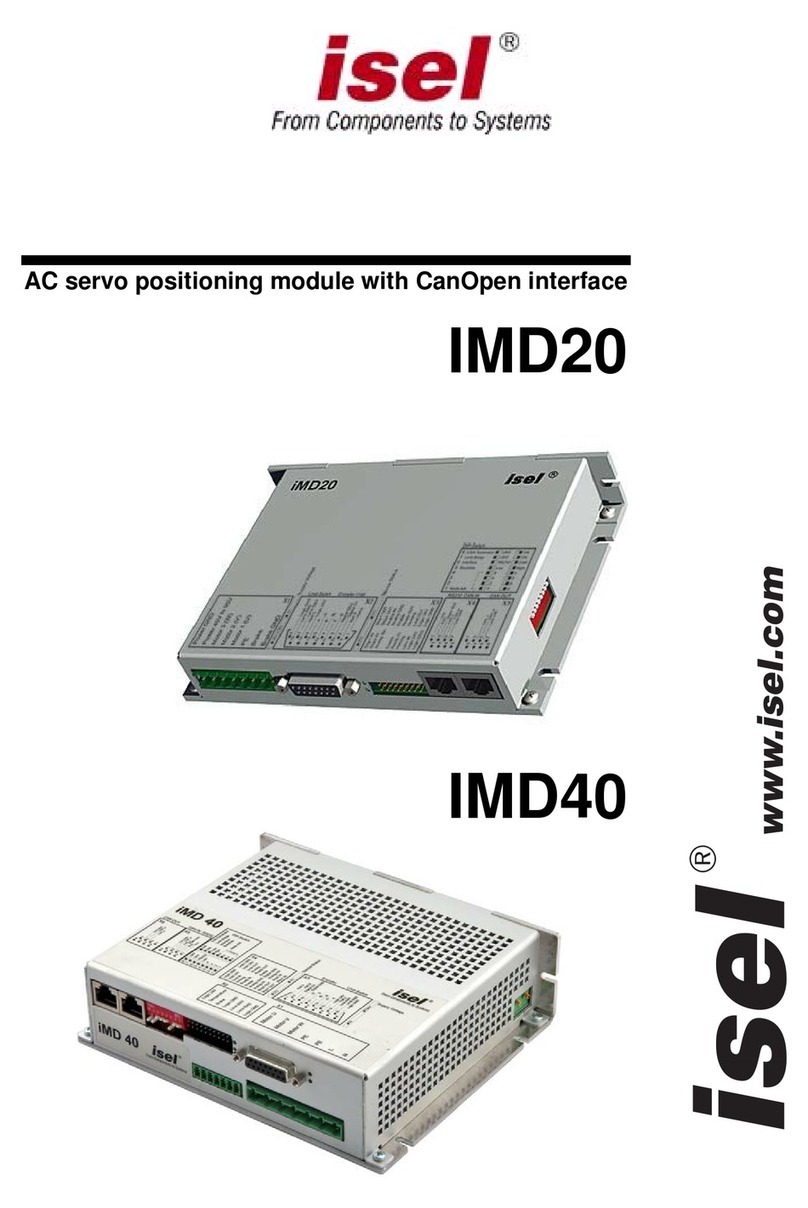
Isel IMD1 User manual

DC servo positioning module with CanOpen interface
UVE8112
IMD10
www.isel.com
®

Positioning module UVE8112, IMD10
Remarks concerning this manual:
Despite the utmost care, print and other errors cannot be excluded.
ithout the prior written content of isel Germany AG, no part of this publication may be reproduced,
tored in a retrieval system or transmitted in any way whatsoever.
o responsibility is accepted for the correctness of the data contained in this manual. Isel Germany AG
ompany reserves the right to make changes to the contents hereof without prior notice.
Telephone: +49-(0)-6659-981-0
Fax: +49-(0)-6659-981-776
If you have any suggestions for improvements and hints as regards errors, don’t hesitate to contact us.
Company: isel Germany AG 2009
All rights reserved.
W
s
N
c
Manufacturer: isel Germany AG
Bürgermeister-Ebert-Straße 40
36124 Eichenzell
Germany
http://www.isel.com
Last Updated: 05/18/2010
2

Positioning module UVE8112, IMD10 Table of contents
Table of contents
Table of contents...........................................................................................3
Overview ........................................................................................................6
Features of the drive module........................................................................................................ 6
Scope of application..................................................................................................................... 6
Operational environment .............................................................................................................7
Description of the drive module...................................................................8
Settings and status display...........................................................................................................8
DIP switch........................................................................................................................ 8
Modes of operation...........................................................................................................9
LEDs UVE8112.............................................................................................................. 10
LEDs IMD10..................................................................................................................11
Hardware description UVE8112................................................................................................12
Connector UVE8112 ...................................................................................................... 12
Frame connector on the rear side of the module................................................ 12
Sub-D9 plug for RS-232......................................................................................12
Jumper settings............................................................................................................... 13
Wiring of the inputs and outputs ....................................................................................14
Digital inputs 1 to 4............................................................................................ 14
Digital outputs 1 to 3..........................................................................................14
Analogue input....................................................................................................14
Encoder connections........................................................................................... 15
CAN ....................................................................................................................15
Hardware description IMD10.................................................................................................... 17
Connectors...................................................................................................................... 17
Frame connector X1 – Connection of the operating voltage 24 V-80 V, motor
and brake............................................................................................................ 17
Frame connector X2 – 15-pin Sub-D – Connection of the encoder, limit switch
and brake............................................................................................................ 17
Frame connector X3 – 20-pin system connection...............................................18
Frame connector X4 – RJ45 - RS-232 and CAN IN ...........................................18
Frame connector X5 – RJ45 – CAN OUT .......................................................... 18
Jumper settings............................................................................................................... 19
Wiring of the inputs and outputs ....................................................................................20
Digital inputs, limit switches, reference switches, Enable..................................20
Digital Ready output........................................................................................... 20
Digital Homing output........................................................................................20
Digital Brake output...........................................................................................20
Digital Limit Switch Chain output...................................................................... 21
Analogue input....................................................................................................21
Encoder connections........................................................................................... 22
CAN ....................................................................................................................22
Data transfer...............................................................................................................................24
Commissioning..........................................................................................................................26
Overview ........................................................................................................................26
Particularities as regards the commissioning of a gantry axis........................................ 26
Examples for the motion control ....................................................................................26
Example 1:..........................................................................................................26
Example 2:..........................................................................................................28
Example 3:..........................................................................................................29
Fault states................................................................................................................................. 30
DcSetup programme...................................................................................31
3

Table of contents Positioning module UVE8112, IMD10
Menus.........................................................................................................................................31
Commands of the File menu...........................................................................................31
The New command (File menu)..........................................................................31
The Open command (File menu).........................................................................31
The Save command (File menu)..........................................................................31
The Save As command (File menu).....................................................................31
The 1, 2, 3, 4 commands (File menu)..................................................................31
The Exit command (File menu)...........................................................................31
Commands of the Connection menu...............................................................................32
The Online Mode On/Off command....................................................................32
The Active Connection / CAN command.............................................................32
The Active Connection / RS232 command..........................................................32
The RS232 Settings command.............................................................................32
The CAN Settings command................................................................................32
Commands of the Commissioning menu........................................................................33
The Step-by-Step Commissioning command.......................................................33
The Random Order command.............................................................................33
The Reset command ............................................................................................33
Commands of the Settings menu ....................................................................................33
The Object Directory command..........................................................................33
Commands of the Tools menu........................................................................................33
The Extended Functions command.....................................................................33
Password.............................................................................................................33
The Firmware Update / Normal command.........................................................34
The Firmware Update / via Bootstrap Loader command ...................................34
Commands of the View menu.........................................................................................35
The Tool Bar command.......................................................................................35
The Status Bar command....................................................................................35
The Serial Interface command............................................................................35
The CAN Monitor command...............................................................................35
The Drive Status command.................................................................................35
The Language command.................................................................................................35
Commands of the ? menu ...............................................................................................35
The Help Topics command..................................................................................35
The Info command ..............................................................................................35
Programme user interface ..........................................................................................................36
Tool bar...........................................................................................................................36
Status bar ........................................................................................................................36
Drive status.....................................................................................................................37
Monitor window for serial interface...............................................................................37
Monitor window for CAN communication.....................................................................38
Programme functions.................................................................................................................39
Create a data connection.................................................................................................39
Offline operation.................................................................................................39
Online operation.................................................................................................39
Choose Active Connection..................................................................................39
RS-232 settings ...................................................................................................39
CAN settings .......................................................................................................40
Commissioning / Adjustment of parameters...................................................................41
Step-by-step commissioning................................................................................41
Random order.....................................................................................................41
Connection dialogue box....................................................................................43
Operation Mode dialogue box............................................................................44
Offset Calibration dialogue box..........................................................................45
Analogue Input dialogue box..............................................................................46
Brake dialogue box.............................................................................................47
Current Settings dialogue box ............................................................................48
Current Controller dialogue box ........................................................................49
Encoder dialogue box.........................................................................................51
Transmission dialogue box .................................................................................52
4

Positioning module UVE8112, IMD10 Table of contents
Velocity Controller dialogue box........................................................................ 54
Direction dialogue box....................................................................................... 56
Acceleration dialogue box.................................................................................. 57
Velocity dialogue box ......................................................................................... 58
Position Controller dialogue box .......................................................................59
Can Interpolation dialogue box.......................................................................... 62
Inputs dialogue box ............................................................................................ 63
Reference Run dialogue box............................................................................... 64
Object Directory dialogue box........................................................................................ 65
Firmware update............................................................................................................. 67
CanOpen protocol.......................................................................................68
Overview....................................................................................................................................68
SDO ...........................................................................................................................................70
PDO ...........................................................................................................................................72
Mapping..........................................................................................................................72
Types of transfer............................................................................................................. 73
SYNC......................................................................................................................................... 74
EMCY........................................................................................................................................ 74
Network management - NMT.................................................................................................... 75
Status diagram................................................................................................................ 75
Boot-Up object ...............................................................................................................76
Monitoring – Guarding................................................................................................... 76
Object Directory ........................................................................................................................ 78
Communications parameter............................................................................................ 78
General communications parameters.................................................................78
PDO / Mapping parameters ...............................................................................82
Device profile parameters............................................................................................... 87
Device control.....................................................................................................87
Mode of operation ..............................................................................................89
Current control...................................................................................................90
Profile Velocity Mode – velocity control with ramp profile ...............................91
Profile Position Mode – position control with ramp profile............................... 92
Interpolated Position Mode – Position control with interpolation.....................95
Homing Mode – Reference run........................................................................... 96
Moving the axis out of a limit switch..................................................................98
Factor Group – Conversion factors.................................................................... 99
General parameters.......................................................................................... 101
Manufacturer-specific parameters ................................................................................ 105
EDS / DCF files....................................................................................................................... 112
Appendix....................................................................................................113
UVE8112 package dimensions..................................................................................... 113
IMD10 package dimensions......................................................................................... 114
Glossary.....................................................................................................115
Index...........................................................................................................116
5

Overview Positioning module UVE8112, IMD10
Overview
The present manual contains all descriptions and documentations required for the wiring,
commissioning and control of the drive module.
It is intended for qualified personnel with basic knowledge of the control and automation technology
as well as of the CAN field bus.
The basics of the CanOpen protocol are described in a separate chapter to the extent that they are
important to the drive process. This chapter also presents an overview of all CanOpen objects of this
module as well as a description of the drive functions.
The 3rd chapter gives a description of the DcSetup programme and serves as a guide to the
commissioning of the drive.
The content of this manual is also provided as online help together with the setting programme.
Features of the drive module
• Supply voltage: 40-95 V (DC)
• Motor current up to 25 A (continuous current: 12 A)
• CAN bus interface according to CanOpen DS301 V4.0 and DS402 V1.0
• RS232 interface
• Analogue input (±10 V) with 11-bit resolution
• Inputs for limit and reference switches
• Digital current, velocity and position control with high cycle times of 100, 244 and 488 µs
(in the mode of operation “CAN bus current control” with a cycle time of up to 70 µs possible)
see Current Controller dialogue box on page 49 and Position Controller dialogue box on page 59
• Brake control
• Gantry operation or synchronous control of 2 modules
• Monitoring of the motor current and encoder signals
• Monitoring of the software through the internal watchdog timer
• Galvanic isolation of processor, power section and I/Os
• Easy firmware update via RS232
Scope of application
The drive module is suited ideally for the control of small- and medium-power brush-type DC motors.
What has to be pointed out is the high torque even at small velocities and the outraging synchronous
characteristics even at low speeds. Thanks to six modes of operation and a high diversity of
adjustable parameters, a broad spectrum of the most diverse applications in the automation
technology and the mechanical engineering can be covered.
The CanOpen interface is an open interface which allows to build up a flexible, extensible plant
structure or to integrate the modules into existing plants.
6

Positioning module UVE8112, IMD10 Overview
Operational environment
To get the full functionality of the drive module the following environmental conditions should be
ensured
• Ambient temperature during operation: from +5oC to 40oC
• Temperature during transport and storage: from -25oC to 55oC and at 70oC for maximum 24
hours
• Maximum height of installation: about 1000m above sea level
• Maximum humidity 50% at 40oC, 90% at 20oC
• Vertical mounting position with appropriate distance each other to allow adequate air circulation
• Shielded motor cable with maximum lenght of 25m and minimal thickness of 1,5mm²
• Protection in power supply
Positioning module UVE8112, IMD10Fehler! Kein Text mit angegebener Formatvorlage im Dokument. •7

Description of the drive module Positioning module UVE8112, IMD10
Description of the drive module
Settings and status display
On the front (UVE8112) or on the side (IMD10) of the module, a DIP switch is provided for settings
concerning the node address, the baud rate and the mode of communication / operation.
Furthermore, LEDs show the current mode of operation.
DIP switch
The DIP switch is only queried, when the module is switched on or after it was reset. During the
operation, a commutation of the switch does not have any effects whatsoever.
• The switches S1 to S5 are used to set up the CanOpen node address. Possible node addresses
are: 1to 30.
! If the Node number 0 is set, Address 1 is used automatically, since 0 is reserved for the
CanOpen master.
! The setting of Node number 31 is provided for the operation of a single-axis control with a
special SPS. The node address is set automatically to Address 6.
• The switch S6 defines the baud rate for the CAN connection and the RS232 interface. In High
Speed Submode the CAN baud rate of the module is determined by the object Can Baud Rate
(2001) (see object directory, manufacturer specific objects, object Can Baud Rate). Under
„Setting->Object directory->Manufacturer specific objects->2001 Can Baud Rate->03 New High
Speed Submode“ of DCSetup you can change the CAN baud rate of the moduel (double click on
the object). After switch off and switch on of the modul the new baud rate is used. When you
change the baud rate of the module do not forget to change also the baud rate in DCSetup and
CANSet. For the interpolation with gantry axis at least a baud rate of 250 kBit/s is needed, for
normal interpolation you need at least 125 kBit/s. Default is 1 Mbit/s.
• The two switches S7 and S8 determine which communication channel has priority (CAN, RS232
or analogue input). In case of an analogue input, one of two set modes of operation is chosen
(current or velocity control).
See "Data transfer" on Page 24.
12345678
Node address
E.g. 17
Baud rate
01
RS-232: 57.6 kBd
CAN: Highspeed Submode
RS-232: 19.2 kBd
CAN: 20 kBit/s
Analogue input
RS-232 / CAN CAN RS-232
Analogue input
(current control) Analogue input
(velocity control)
8

Positioning module UVE8112, IMD10 Description of the drive module
Modes of operation
Here, two groups of modes of operation are available differing from each other mainly in the type of
the controller release. In case of the CanOpen modes of operation, the internal state (state machine)
is controlled via the Can bus or the serial interface, while there are only two states for the other
modes of operation (Enabled, Disabled) which are linked directly with the enabling signal (Input 4).
CanOpen modes of operation
(Release via Can or RS232)
Other modes of operation
(Release via input 4)
Positioning (profile position mode)
Velocity control with ramps (profile velocity mode)
Reference run (homing mode)
Interpolation (interpolated position mode)
Current control (analogue input)
Velocity control (analogue input)
Current control (analogue input)
Velocity control (analogue input)
The active mode of operation of the drive module is defined through the settings of the DIP switch on
the front side and through the “Modes of operation” parameter ("Modes of Operation", 6060h).
See “Mode of operation” on page 89.
When the module is switched on, the DIP switch is queried at first. The switch S8 defines whether the
“Mode of operation” parameter is evaluated or whether a set mode of operation is used.
S8 Mode of operation
Modes of
operation
1 Profile position mode (profile position mode)
3 Profile velocity mode (profile velocity mode)
6 Reference run (homing mode)
7 Interpolation (interpolated position mode)
-1 Current control, analogue input
-2 Velocity control, analogue input
0 The mode of operation is
defined by the “Modes of
operation” parameter.
-3 Moving the axis away from a limit switch
S7
1 Current control, analogue input
1 The mode of operation is set
firmly (depending on S7).
0 Velocity control, analogue input
9

Description of the drive module Positioning module UVE8112, IMD10
LEDs UVE8112
Via the LEDs on the front, it is possible to indicate the existence of the two main supply voltages.
Furthermore, the current mode of operation of the module can be viewed here (STS1 and STS2).
For this, see: "Status diagram" on page 75 and "Device control" on page 87.
In the Operation Enable state, the two related LEDs (STS1 and STS2) are used to show the current
motor current in the negative and positive direction. Concerning this, the maximum brightness
corresponds to the peak current.
In case of a fault (Fault state), the two-digit error code of the current fault is given via a blinking code.
1st digit: number of blinking impulses of both status LEDs.
2nd digit: number of blink impulses of LED STS2.
See "EMCY" on page 74 for the description of the error code.
In case of a missing enabling signal, all three LEDs (STS1, STS2 and CAN) blink about once every
1.5 seconds.
+5V
+70V
Drive status
Switch On Disabled
Ready To Switch On
Switched On
Operation Enable
NMT state OPERATIONAL
Fault
Blinking interval about 0.5 s
CAN warning
No enabling signal (Input 4)
Blinking interval about 1.5 s
STS1
STS2
CAN
NMT state PRE-OPERATIONAL
10

Positioning module UVE8112, IMD10 Description of the drive module
LEDs IMD10
1
10
5V
24V-80V
STS1
STS2
1
With the help of the LEDs on the front side, it is possible to indicate the existence of the two main
supply voltages. Furthermore, the current mode of operation of the module can be viewed here
(STS1 and STS2).
For this, see "Status diagram" on page 75 and Device control" on page 87.
In the Operation Enable state, the two related LEDs (STS1 and STS2) are used to show the current
motor current in the negative and positive direction. Concerning this, the maximum brightness
corresponds to the peak current.
In case of a fault (Fault state), the two-digit error code of the current fault is given via a blink code.
1st digit: number of blink impulses of both state LEDs.
2nd digit: number of blink impulses of LED STS2.
See "EMCY" on page 74 for the description of the error code.
In case of a missing release signal, all three LEDs (STS1, STS2 and CAN) blink about once every
1.5 seconds.
+5V
+ 24V - 80V
Drive status
Switch On Disabled
Ready To Switch On
Switched On
Operation Enable
Fault
Blinking interval about 0.5 s No enabling signal (input 4)
Blinking inteval about 1.5 s
STS1
STS2
11

Description of the drive module Positioning module UVE8112, IMD10
Hardware description UVE8112
Connector UVE8112
Frame connector on the rear side of the module
dbz
2
4
6
8
10
12
14
16
20
22
26
30
24
28
32
D b Z
2 ←Output 2 ←Output 1 →+24 V (for outputs)
4→Input 2 →Input 1 24 V GND
6→Input 4 →Input 3 Output 3
8↔CAN Low ↔CAN High CAN GND
10 →Analogue GND →Analogue input + →Analogue input -
12 ←Encoder voltage 5 V - Encoder GND
14 →Encoder /Z →Encoder /B →Encoder /A
16 →Encoder Z →Encoder B →Encoder A
20 →VSS_W (Processor section: 18-30 V)
22 →VSS_M (Power section: 40-95 V)
24 ←Motor output A
26 ←Motor output B
28 -
30 GND_W (Processor section)
32 GND_M (Power section)
Sub-D9 plug for RS-232
Pin 1 2 3 4 5 6 7 8 9
Signal - RxD TxD - GND - - - -
12

Positioning module UVE8112, IMD10 Description of the drive module
Jumper settings
For the normal operation, no settings via jumpers are required. Only for the loading process of a new
software version by means of the bootstrap loader, the corresponding jumper has to be connected.
See also "The Firmware Update / via Bootstrap Loader command" on page 34.
Processor
Bootstrap jumper
NMI
Reset
+ 5V
Gnd
P1.0
P1.1
P1.2
P1.3
Frame connector
DIP switch
13

Description of the drive module Positioning module UVE8112, IMD10
Wiring of the inputs and outputs
Digital inputs 1 to 4
The evaluation of the inputs can be set by means of software.
See “Inputs dialogue box” on page 63.
Input 1 ... 4
V
CC
3
4
56
Digital outputs 1 to 3
• Output 1 indicates the operational readiness of the module and is set only, if the module
software works correctly (monitoring through internal watchdog timer).
• Output 2 can be used to shunt the limit switch in the safety circuit. It is set during the
reference run (on the limit switch).
• Output 3 is used for the brake control. The way in which the brake is controlled can be
defined by means of the software.
+24V
Output 1 ... 2
2
1
3
BSP30-SOT223
10K A
K
1N4002-SMD
1
23
4
GND 24V
TLP124
10K
Analogue input
The analogue input is preset for a voltage level in the area of -10 V … +10 V. The signal can either
be connected to the positive input (+) or to the inverting input (-). The reference potential is always
Analogue GND.
31
LM324SO
10K
10K
10K
10K
10K
10K
100PF
100PF
100PF
100PF
2-
+
Analogue input +
Analogue input -
Analogue GND
14

Positioning module UVE8112, IMD10 Description of the drive module
Encoder connections
The drive module is preset for the connection of a quadrature incremental encoder with index signal.
The transfer of the signals is carried out according to the RS422 specification. It is recommended to
use shielded cables twisted in pairs for the encoder wiring.
The voltage supply of the encoder (5 volt) is provided by the drive module. The maximum supply
current amounts to 100 mA.
VCC VCC
3
5
13
11
4
9
10
15
14
7
6
1
2
12
Y1
Y2
Y3
Y4
En1
B4
A4
B3
A3
B2
A2
B1
A1 En2
LTC489-SOL16
120
120
2K2
2K2
2K2
2K2
2K2
2K2
120
Encoder A
Encoder B
Encoder Z
Encoder /A
Encoder /B
Encoder /Z
+5V Encoder
Encoder GND
VCC
CAN
The structure of the Can network is to be realised so as to guarantee that a 120 ohm terminating
resistor is provided on both sides. The drive module itself does not possess a terminating resistor.
The stub lines leading from the bus to the individual modules should not be longer than 50 cm in
case of a baud rate of 1 Mbit/s.
120
120
Axis 1 Axis n…
Device X
CAN High
CAN Low
CAN GND
15

Description of the drive module Positioning module UVE8112, IMD10
For the CAN wiring, it is recommended to use twisted shielded cables with a characteristic
impedance of 108 to 132 ohms. In case of very small network extensions, it may be possible to
dispense with the connection of the reference potential (CAN ground) (not recommended).
16

Positioning module UVE8112, IMD10 Description of the drive module
Hardware description IMD10
Connectors
All connectors are provided on the front of the drive module.
1
9
1
X1 X2 X3 X4 X5
Frame connector X1 – Connection of the operating voltage 24 V-80 V, motor and brake
Pin Signal
1 GND_M (power section)
2→VSS_M (power section: 40–95 V)
3←motor output A
4←motor output B
5ground
6←brake
7GND_24V
Frame connector X2 – 15-pin Sub-D – Connection of the encoder, limit switch and brake
Pin Signal
1 not connected
2←encoder voltage: 5 V
3→encoder /Z
4→encoder /B
5→encoder /A
6+24 V
7→limit switch 1
8 GND_24V
9 not connected
10 encoder GND
11 →encoder Z
12 →encoder B
13 →encoder A
14 →reference switch
15 →limit switch 2
17

Description of the drive module Positioning module UVE8112, IMD10
Frame connector X3 – 20-pin system connection
Attention technical modification: This frame connector is expanded from 16 to 20 pins. The plug
connection is not valid for the 16 pin connector. The standstill monitoring is added (see object index
0x6510 subindex B)
Pin Signal
1 Stop 1 IN: standstill monitoring channel 1 input
2 Stop 2 IN: standstill monitoring channel 2 input
3 →analogue input +
4digital GND
5→Enable input
6→Ready In input
7←Homing output
8→limit switch chain input In
9+24 V
10 GND_24 V
11 Stop 1 OUT: standstill monitoring channel 1 output
12 Stop 2 OUT: standstill monitoring channel 2 output
13 →analogue input -
14 →analogue GND
15 →Enable input
16 ←Ready Out output
17 ←Homing output
18 ←limit switch chain output Out
19 +24 V
20 GND_24 V
Frame connector X4 – RJ45 - RS-232 and CAN IN
Pin 1 2 3 4 5 6 7 8
Signal RS232
TxD RS232
RxD RS232
GND
↔
CAN
Low
↔
CAN
High
CAN
GND
- -
Frame connector X5 – RJ45 – CAN OUT
Pin 1 2 3 4 5 6 7 8
Signal
-
-
-
↔
CAN
Low
↔
CAN
High
CAN
GND
-
-
18

Positioning module UVE8112, IMD10 Description of the drive module
Jumper settings
For the normal operation, no settings via jumpers are required. Only for the loading process of a new
software version by means of the bootstrap loader, the bootstrap jumper has to be connected.
See also "The Firmware Update / via Bootstrap Loader command" on page 34.
Every drive module comprises a 120 ohm terminating resistor, which is activated through the
connection of the terminating resistor jumper. See also “Wiring of the inputs and outputs – CAN“ on
page.
Bootstrap jumper
Terminating resistor
jumper
19

Description of the drive module Positioning module UVE8112, IMD10
Wiring of the inputs and outputs
Digital inputs, limit switches, reference switches, Enable
The evaluation of the inputs can be set by means of software.
See “Inputs dialogue box” on page 63.
P2.0
GND 24V
Input
VCC
4K7 1
2
4K7
10K
2K2
3
4
TLP124
10NF 56
74HCT14SO
Digital Ready output
The Ready output is designed as a potential-free contact. It indicates the operational readiness of
the module and is only set, if the module software works correctly (monitoring through internal
watchdog timer). The design as a potential-free contact makes it possible to easily link several
Ready outputs. This sum signal can be processed e.g. in the safety circuit.
12
4
1
2
3
+24V
REL1 REL1
Ready In
Ready Out
Digital Homing output
The Homing output can be used to shunt the limit switch in the safety circuit. It is set during the
reference run (on limit switch).
DGND
1
23
4
K
A
12
TLP124
+24V
Homing output
Digital Brake output
The Brake output is used for the brake control. The way in which the brake is controlled can be
defined by means of the software.
20
This manual suits for next models
1
Table of contents
Other Isel Control Unit manuals