●Structuraldrawings
●Installation
(1)Usepaintthinnerorothermeanstowipeoffany
corrosion,dirt,orothersubstancefromthesurfaceof
theshaft,thenapplyalightcoatofoil.
(2)Applyalightcoatofoiltothecouplinginnerdiameter
parts,taperedparts,andthethreadsandheadseatsof
thelockbolts.
(2)Removetheclampboltsfromthediscpartofthe
provisionallyinstalledcoupling,andseparatethebody
anddisc.Onlythenecessarynumbersofwashers,bolts,
andotherpartsareprovided.Becarefulnottoloseany
ofthem.
(3)Setthedistancebetweenflangesurfaces(Table1)
accordingtothemodel.(Figure2)
◇Usingtheproductafterunpackagingwithoutapplyingoil
toitmaycauseadecreaseinallowabletorque.
(3)Machinethemotormountpartaccuratelysothatthe
misalignmentbetweenthe2shaftsisatorbelowthe
tolerancevalue.
CouplingInstructionManual
ASeries(AS,AT,AD,AL)
Forsafeuseoftheproduct
ThankyouforyourpurchaseofanISELproduct.
Inordertousetheproductsafelyandobtainthe
designatedfullperformance,pleasebesuretoreadthe
followingitems.
◎Readthisinstructionmanualcarefullyandunderstand
thecontentsbeforeusingtheproduct,andbesureto
observeallinstructionsinthemanualandusethe
productcorrectly.
◎Besurethatyoufullyunderstandtheinformationrelated
tothedeviceandsafetybeforeusingtheproduct.
◎Afterreading,besuretostorethismanualcarefullyso
thatitcanbereferredtoatanytimewhenneeded
duringuse.
Thismanualclassifiesimportantprecautionsintotwo
categories:DANGERandWARNING.
◇Checkthattheproductistheoneyouorderedandthat
thereisnodamagetoit.Iftheproductisnottheone
youorderedorisdamaged,thereistheriskofinjuryto
operators,damagetoequipment,andotherdamage.
◇Neverusemolybdenumoiloroilwhichcontainsan
extreme-pressureadditive.Doingsomaycausealarge
decreaseinallowabletorque,resultinginslipping.
◇Iftheshaftincludesakeygroove,itcanbeusedas
longasthegroovewidthisasprescribedintheJIS
standard.Howeverthemaximumallowabletorqueis
reducedby15%-20%.Removeanyburrsonthekey
TheASandATSeriesareflexible-typecouplingsthat
permitadeflectionanglebetweenthe2shafts,while
theADandALSeriesareflexible-typecouplingsthat
permitbothcenterdeviationandadeflectionangle
betweenthe2shafts.Theshafttolerances,surface
roughness,centeringaccuracy,andcorrecttighteningof
thelockboltsareveryimportantfactorsinorderto
obtainfullperformancefromeachseries.Ifyouhave
anyquestions,pleasecontactadealerorourcompany.
DANGER
WARNING
WARNING
Incorrectuseorhandling
willproducedangerous
conditionsthatmayresult
indeathorseriousinjury.
Incorrectuseorhandling
willproducedangerous
conditionsthatmayresult
ininjury.
Thereisalsotheriskof
propertydamage.
DANGER WARNING
◆Whenusingthisproduct,besurethatthenecessary
mechanisms(covers,enclosures,etc.)forensuringthe
safetyoflifeandhealthareinstalledontheequipment.
◆Wearclothingandprotectivegearthatissuitableforthe
work.
◆Keeptheworkareacleanandorderly,andworksafely
inordertopreventsecondaryaccidents.
◆Intheenvironmentwheretheproductoperates,install
safetymechanismsontoallpartswhichmaybea
dangertotheoperator.
◆Whenperformingmaintenanceorinspections,turnOFF
themotorpower(powersupply)andcheckthatthe
machinehasfullystoppedbeforebeginningwork.
◆Beforeusingliftequipment,installsafetymeasureson
theequipmenttopreventfalling.Thereistheriskof
deathorinjury,aswellasdamagetotheequipment,if
theliftpartfalls.
◆Iftheproductisusedfortransportingpersons,installthe
necessaryequipmentforsafety.
◆Donottouchtheproductwhileitisoperating.Doingso
mayresultininjury,damagetotheproduct,orother
damage.
◆Donotusetheproductforanypurposeotherthanthe
designatedpurpose,anddonotmodifytheproduct.
Thereistheriskthatthedesignatedaccuracyand
performancewillnotbepossible.
◆Ifabnormalnoiseorvibrationoccursduringwork,
immediatelydiscontinueoperationandinspectthe
equipmentandthisproduct.Ifuseiscontinuedwithout
inspecting,thereistheriskofinjurytooperators,
damagetoequipment,andotherdamage.
groovebeforeusing.
◇Iftheproductisreused,checkthatthereisno
deformation,damage,orotherproblemwiththeproduct
oranyofitscomponentsbeforeuse.Ifthereisdamage,
deformation,orotherproblem,replacewithanew
product.
◇Whentighteninglockbolts,besuretouseatorque
wrenchthatincludesatorqueadjustmentscale,and
tightenatthedesignatedtighteningtorque.Useofa
plate-typetorquewrenchmaycauseslipping,
deformation,andothertroublebecauseitisdifficultto
checkthedesignatedtorque.
◇Neveruseanyboltotherthanthedesignatedbolt.There
istheriskofdamagetothebolt,resultinginan
accident.
◇Inordertoensurethedesignatedperformance,an
oppositeshaftwithtolerancegradeh7andsurface
roughnessofRa1.6orlessisrecommended.
◇Inthecaseofahollowshaft(pipe),dependingonthe
thicknessitmaynotbepossibletoobtainsufficient
surfacepressure.Pleasecontactourcompany.
◇Installwithinthetolerancevaluesforcenterdeviation,
deflectionangle,andendplay.Thereistheriskof
damagetotheproduct.Inparticular,centeringaccuracy
hasaneffectonvibrationandthelifetimeofthe
coupling.
◇Itisrecommendedthattheproductbeusedwithin1/2
orlessofthedisplacementtolerancevalues.
◇Iftheproducthasspecialspecifications,itmaydifferin
partsfromthecontentsofthisinstructionmanual.
Pleasecontactadealerorourcompany.
◇Iftheboltsaretightenedwhenthecouplingisnot
connectedtoanything,thecouplingmaybecome
deformedandberenderedunusable.Thereforecheck
thattheshaftisfullyinsertedintothecouplingwhen
tighteningthebolts.
◇Duetothecouplingstructure,thereistheriskofinjuryif
theusergraspsthecornersordiscpart.Therefore
exercisesufficientcautionwhenhandling.
LL
48756 3 1 2
6 5 4 3 1 7 2
ASSeries
ALSeries
6 2 3 75 41A 1B
ATSeries
4
6 5 3 7 8 4 1 2
ADSeries
1.Body 4.Washer
1A.BodyA5.Clampingscrew
1B.BodyB6.Lockingscrew
2.Sidering 7.Unut
3.Disk 8.Spacer
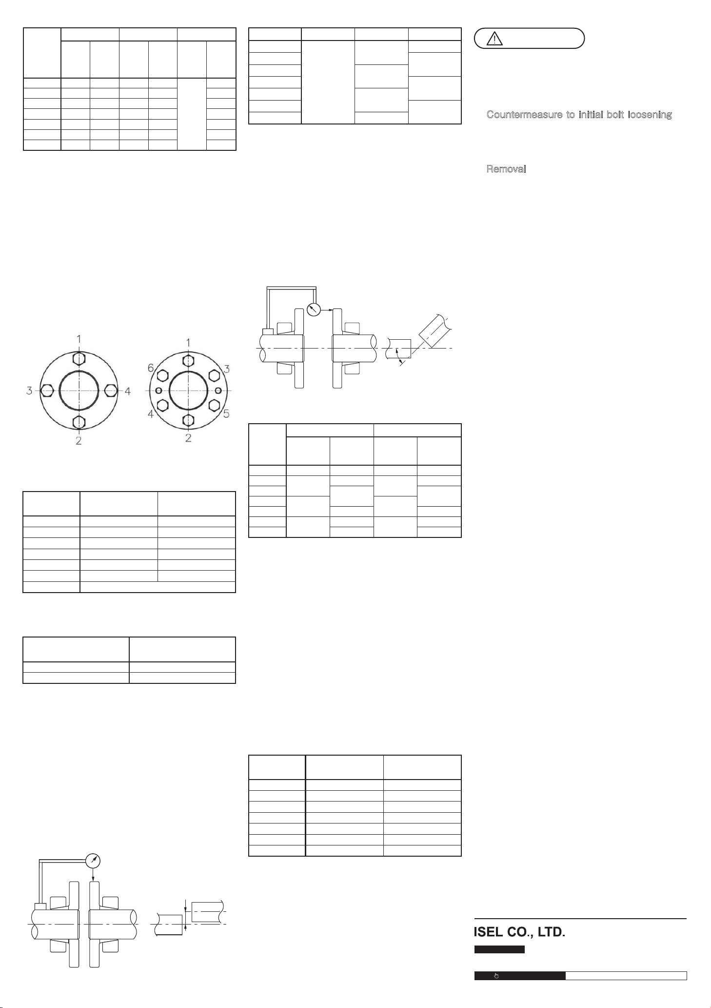
●Installationprocedure
(1)Checkoutputmotorshaftcenteringaccuracy.
Confirmcenteringaccuracybymeasuringtheoutput
motorshaftbeforeinstallingthecoupling.
Setthegaugeasshowninordertomeasuremotor
shaftoff-centering(Figure.1).
Precautions:Themotorshaftoff-centeringamountis
establishedbyeachmanufacturerbutmay
alreadyhaveoccurredatthisstage.
(Figure1)
(Figure2)
Motor