ISHIDA OMNi-4000 Use and care manual

OMNi-4000
Film Feeder Replacement Manual
Revision 4, June 2009
IMPORTANT
• Do not carry out replacement and related operation and services
until thoroughly understanding the contents of this manual.
• Keep this manual available at all times.
Manual No. 98076 ISHIDA CO., LTD

OUTLINE
■Purpose of this manual
This manual is used for reference when removing or replacing the Film Feeder.
■Symbols in the description
Warning symbols
Symbol Meaning
WARNING Indicates information that, if not avoided, may result in loss of life or
serious injury.
CAUTION Indicates information that, if not avoided, could result in relatively
serious or minor injury, damage to the machine or faulty operation.
Explanatory symbols
Symbol Meaning
NOTE Indicates information to call or emphasize for attention to the note.
■Readers of this manual
This manual is written for use by qualified service personnel to perform maintenance
services for the machine.
• Use by anyone except the above personnel is not permitted.
• This manual may be revised in accordance with modifications made to the machine.
• Copying any part of this manual is prohibited without written permission from Ishida Co.,
Ltd.
© ISHIDA CO., LTD. 2004-2009 All rights are reserved.
OMNi-4000 Film Feeder Replacement Manual ii

CONTENTS
OUTLINE..............................................................................................................ii
1. OVERVIEW.......................................................................................................1
Disassembly...................................................................................................................... 1
Time ................................................................................................................................... 1
Personnel .......................................................................................................................... 1
Required Tools and Materials ......................................................................................... 1
2. DISASSEMBLY PROCEDURES......................................................................2
3. REPLACING FEEDER BELT.........................................................................11
4. ASSEMBLY PROCEDURES..........................................................................11
5. BELT TENSIONING PROCEDURES.............................................................11
OMNi-4000 Film Feeder Replacement Manual iii

1. OVERVIEW
Follow the instructions in this manual to replace one or both of the Film Feed Belts.
To replace the Film Feed Belt(s) the Film Feeder Unit(s) must be removed from the OMNi.
Disassembly
This basic disassembly order is:
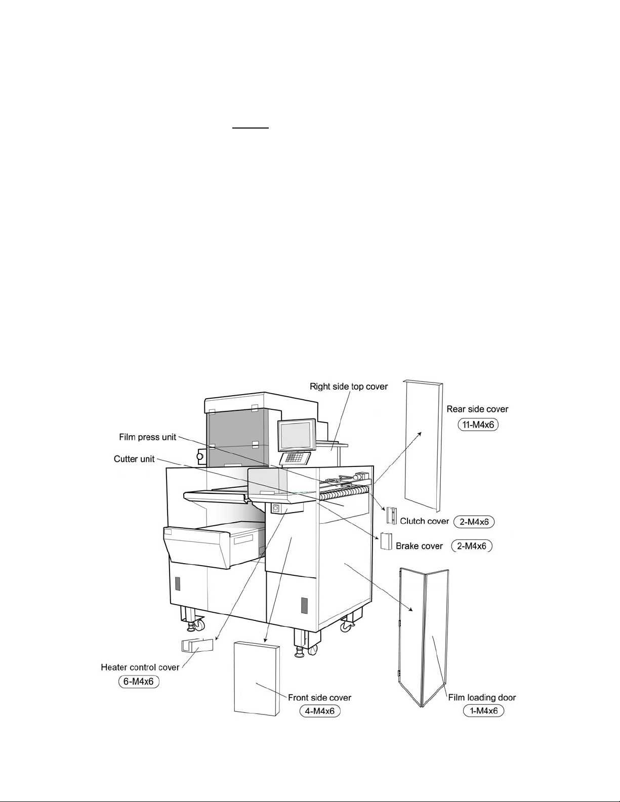
a. Remove right side outer covers: front, side, and rear.
b. Disconnect right side Film Press Unit and Cutter Unit wiring.
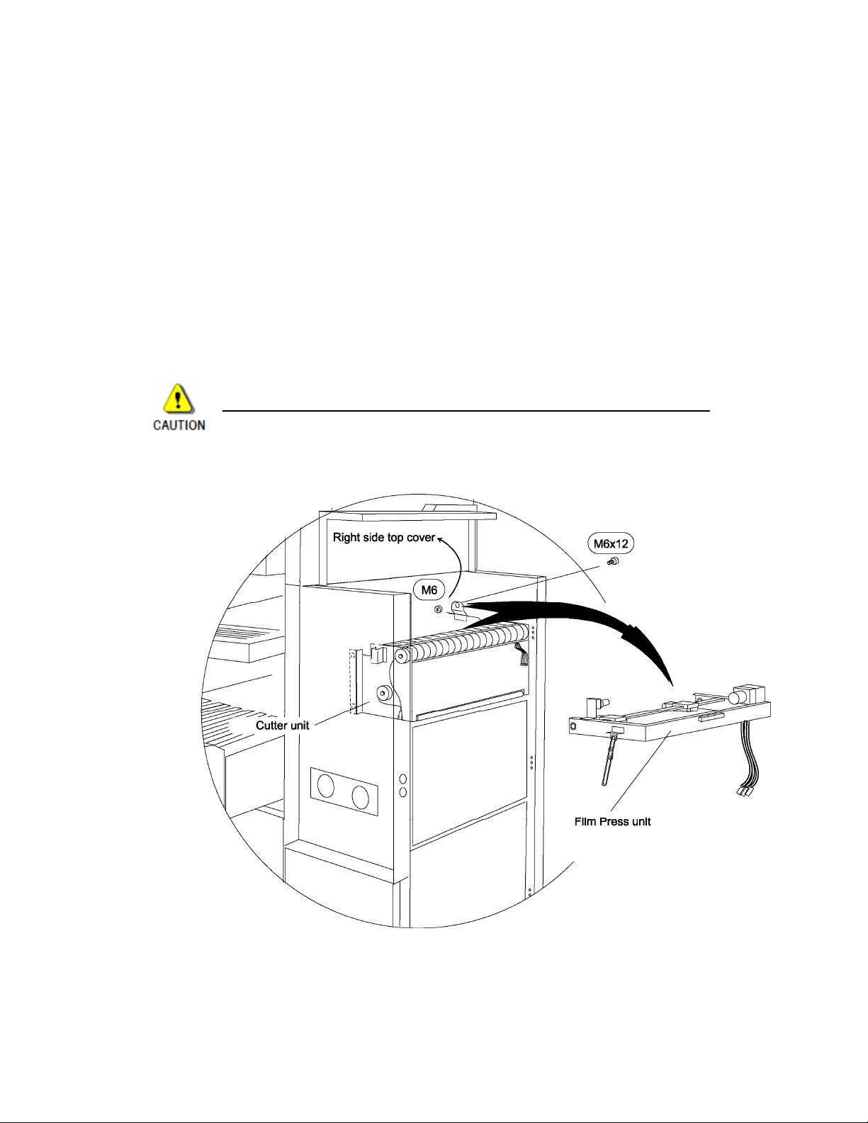
c. Remove right side Film Press Unit.
d. Remove right side Cutter Unit.
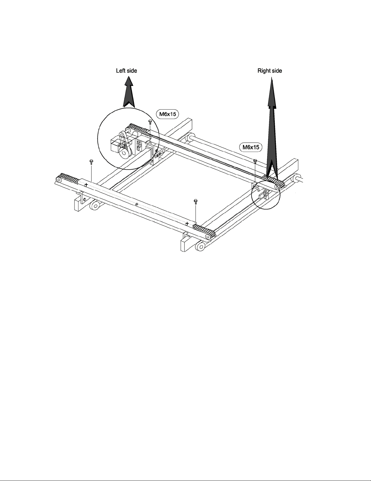
e. Disconnect right and left side Film Feeder Unit wiring.
f. Dismount and remove Film Feeder Unit(s).
g. Replace Film Feed Belt(s).
h. Reassemble the above components.
The procedures for these steps are listed in detail in the following pages.
Time
Allow three hours to replace one Film Feed Belt. Allow four hours to replace both belts.
Personnel
Removing the Film Feeder Units to replace the film belts is a complicated task that is best
performed by two service technicians.
Required Tools and Materials
1. Wrench set, open end, metric
2. Socket set, metric
3. Screw drivers, straight and cross
4. Pliers
5. Diagonal cutters
6. Hexagonal (Allen) wrench set, metric
7. Cable ties, plastic
8. Threadlock [Loctite®model 242 or 248 (blue)]
OMNi-4000 Film Feeder Replacement Manual 1

2. DISASSEMBLY PROCEDURES
In order to remove the Film Feeder unit, disassemble the wrapper in the following order.
(After the removal, reassemble the machine in the reverse order.)
1. Perform a Roll Set for the left side.
NOTE: The rear Film Feeder may be pushed forward or back when the power is
disconnected.
2 Turn off the power switch and disconnect the power plug.
3. Unthread film from both sides.
For steps 4 - 9, see Fig. 1.
4. Remove front covers:
• Remove Heat Belt temperature control cover - 6 screws, M4x6.
• Remove front right side cover - 4 screws, M4x6.
5. Remove Rear side cover - 11 screws, M4x6.
6. Raise the Right side top cover.
7. Remove the M4x8 truss headed screw securing the ground wire on the right-side bi-fold
Film loading door. Remove the door by lifting off the hinges.
8. Loosen two M4x6 truss headed screws to take off the Brake cover.
9. Loosen two M4x6 truss headed screws to take off the Clutch cover.
Fig. 1
OMNi-4000 Film Feeder Replacement Manual 2

For steps 10 - 12, see Fig. 2.
10. Disconnect the following wires on the rear side after cutting the cable tie fasteners and
release each of the harnesses from the clamps.
• Wire No. ring [D0B]
• Wire No. ring [D1B]
• Wire No. ring [S5B]: Disconnect the cable from the Cutter home position photo sensor.
(NOTE: No in-line connector is provided.)
• Ground wire (secured by cross screw)
11. Disconnect the following wires on the front side after releasing each of the wires from the
clamps. These wire connections are located under the Exit Heater Conveyor.
• Wire No. ring [D2B]
• Wire No. ring [D3B]
• Wire No. ring [B2]
• Wire No. ring [B4]
• Wire No. ring [DC0]
• Wire No. ring [DC1]
Fig. 2
OMNi-4000 Film Feeder Replacement Manual 3

For step 12, see Fig. 3.
12. Before removing the Film Press unit, check if Nylock®nuts (M6) are installed on the two
M6x12 socket head pivot bolts. If present remove one nut each from the front and rear
bolts.
NOTE: Remove the Nylock®nuts (M6) from above using a socket wrench. The Film
Press must be in the up (not selected) position to access the nuts. If the right
side Film Press unit is lying flat, the Nylock®nuts can be removed from the
bottom side using an open end wrench.
For step 13, see Fig. 2.
13. Remove two of the M4x8 flat-head Philips screws of the Film Press unit Latch Bracket.
CAUTION: do not lose the spacer washers.
For steps 14 - 15, see Fig. 3.
14. Remove the rear M6x12 socket head bolt at the pivot point of the Film Press unit using a
5mm hexagonal wrench. Slide the Film Press unit up and to the rear and off the front
socket head bolt.
Take care not to lose or damage the Film Press unit plastic pivot bushings.
15. Remove the Film Press unit from the main body.
Fig. 3
OMNi-4000 Film Feeder Replacement Manual 4

For steps 16 - 18, see Fig. 4.
16. Loosen the M13 inside shaft / M10 bolt to slide the Tension pulley as shown in Fig.4.
17. Remove the timing belt “Belt-AT5” from the Roll and Cutter pulleys.
18. Remove four of the M6x15 bolts and pull out the Cutter unit from the main body (10mm
wrench).
Fig. 4
OMNi-4000 Film Feeder Replacement Manual 5

For steps 19 - 25, see Fig. 5.
19. Raise the Film Press unit on the left side of the main body.
20. Disconnect the following connectors on the right and left sides.
RIGHT LEFT
FRONT • FCFR • FCFL
REAR • FCBR • FCBL
• Ground wire [NOTE: Rear Film Feeder unit, right side only]
21. Remove the following bracket parts on the left side of the main body.
• Bracket: Fan by removing two of the M4x8 bolts.
• Bracket: Plate (non-reflective black) by removing two of the M4x8 bolts (8mm wrench).
• Bracket: Socket plate by removing two of the M4x10 bolts (8mm wrench).
NOTE: If it is possible to "walk" the Timing belt “375L” on and off the pulley move to step 25.
If this is not possible proceed from step 22.
22. Remove the cover above the Film Roll to expose the circuit boards - 6 screws.
23. Remove the Film Pieces catch tray and tray support plate from left side - 4 bolts.
NOTE: Cover the exposed circuit boards with a sheet of film to catch any dropped
screws, etc.
24. Loosen the M4 bolt (8mm wrench) to slide the Tension pulley.
25. Remove the Timing belt “375L” from the drive pulley of the Film Feeder unit.
Fig. 5
OMNi-4000 Film Feeder Replacement Manual 6

For step 26, see Fig. 6
26. Remove the two M6x15 bolts fastening the Film Feeder to the mounting blocks - two
bolts per each Film Feeder unit.
Fig. 6
OMNi-4000 Film Feeder Replacement Manual 7

For steps 27 - 29, see Fig. 7
27. Dismount the Film Feeder unit by the following steps:
• Pull the right and left wrapping plates inwards before removing the Film Feeder.
• Pull up the left end of the Film Feeder to disengage from the pulley slot.
• Slide the Film Feeder off the two mounting blocks.
28. Rotate the Film Feeder unit 90 degrees toward the back (white belt faces to the rear).
29. Remove the Film Feeder from right side of the wrapper.
Be careful not to damage any of the loose components
on the left side of the Film Feeder unit during removal.
Fig. 7
OMNi-4000 Film Feeder Replacement Manual 8

For steps 30 - 35, see Fig. 8
30. Remove two Covers:
• Upper cover (stainless) - remove two M4x6 cross screws.
• Lower cover (anodized) - remove four M4x6 cross screws.
31. Remove two solenoid bracket plates (one at each end) - four M4x8 bolts each.
32. Dismount the following parts from the right end of the Film Feeder unit:
• Bracket: Plate (non-reflective, black) - two M4x8 bolts (8mm wrench).
• Bracket: Connector socket plate - two M4x8 bolts (8mm wrench).
• Bracket: Fan - two M4x8 bolts.
33. Remove the green film feed belt (optional).
(It provides less resistance during installation of the new white Film Feeder Belt).
34. Loosen the M4 inside tensioner nuts on the idler pulley.
35. Remove the tensioner bracket from the inner side of the idler pulley.
NOTE: The side where the Film Clamps open and where the white Film Feeder belt will
be removed is the inner side of the Film Feeder.
OMNi-4000 Film Feeder Replacement Manual 9

Fig. 8
OMNi-4000 Film Feeder Replacement Manual 10

3. REPLACING FEEDER BELT
1. Cut or walk off the old white Film Feeder Belt (DT5).
2. Check for and remove any film pieces on the gears, pulleys, solenoids, etc.
3. Put on a new Film Feeder Belt (DT5), starting from the fixed pulley end and finally
walking on to the tensioned pulley end.
IMPORTANT: New white Film Feeder Belts (DT5) are supplied with one edge beveled at 45
degrees. This edge must be placed to the top, outside. See Fig. 9
Front Rear
View from side
Fig. 9
4. ASSEMBLY PROCEDURES
Go through steps 1 - 35 of the disassembly procedures listed in the Section 2 in the reverse
order.
5. BELT TENSIONING PROCEDURES
See Fig. 10
1. Return the tensioner nuts to the original positions.
2. After the Film Feeder Unit has been reinstalled, enter the Test Menu, section
Wrapper/Applicator Adjust and perform step 9: Film Feed (Left) to check the belt
tracking. If a belt is not centered, adjust the tensioners as needed.
Example: If the belt tracks to the left, slowly tighten the left tensioner until the belt is
centered. It is acceptable for the belt to “walk” from side to side on the
pulley.
Fig. 10
OMNi-4000 Film Feeder Replacement Manual 11

44 SANNO-CHO, SHOGOIN, SAKYO-KU Rice Lake Weighing Systems
KYOTO, 606-8392 JAPAN 230 West Coleman Street
PHONE: 81-75-771-4141 Rice Lake, WI 54868
FACSIMILE: 81-75-751-1634 (715) 234-9171
www.ishidajapan.com www.ricelake.com/retail
Table of contents
Other ISHIDA Industrial Equipment manuals
Popular Industrial Equipment manuals by other brands

B&R
B&R Power Panel 500 Series user manual

Pittsburgh Automotive
Pittsburgh Automotive 95979 Owner's manual & safety instructions

ABB
ABB Relion 670 series Applications manual

schmersal
schmersal AZM400Z-ST-I2-1P2P-T manual

hager
hager univers Z ZU VT APZ2 Series Mounting instructions

ABB
ABB HT575645 Operation manual