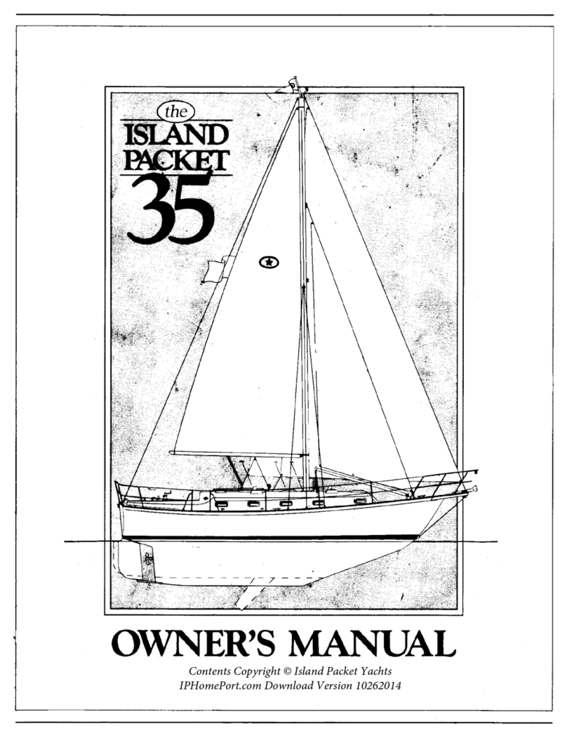
ISLAND PACKET Cat 35 User manual

I
I
I
I •
'~
I
i
I ,
.J
I
,,
, I
I
,.
.
t '
..
~-j.____,-_~_;--0~_-_-
___
·_;
~~~~--
j
~
_
-
:
_______
--_--_-~__,
\ I
~
.t._
-
-_,..
- - - - -
~
·
,_'
""'\
-
.,-,
.;,..
"!'"
' - " v
~
\
'"----
-----
...
.I
OWNER'S
MANUAL
- - 1
I
I
I
.I
I
I
I
i
i
----·
------------
-
----------
·
---
.-
--
Contents Copyright © Island Packet Yachts
IPHomePort.com Download Version 090716

I
l
Hello!
Congratulations
on
the
purchase
of
your
Packet
Cat
and
welcome
to
our
distinctive
family
of
owners
.
We
take
great
pride
in
our
yachts
and
appreciate
your
endorsement
of
our
efforts
by
select-
ing
the
Packet
Cat.
This
manual
is
intended
to
help
you
understand
and
enjoy
your
new
yacht
more
thoroughly
and
to
assist
in
maintaining
and
operating
it
in
a
safe
and
efficient
manner.
Individual
instruction
man-
uals
from
the
various
manufacturers
of
installed
equipment
may
be
found
in
your
owner's
package
for
more
in-depth
information
if
required.
Also
your
authorized
Packet
Cat
dealer
should
be
able
to
answer
additional
questions
you
may
have,
or
feel
free
to
call
our
manufacturing
facility
for
further
assistance
.
We
wish
you
years
of
pleasurable
sailing
experiences
with
your
new
yacht,
and
hope
that
your
enthusiasm
and
pride
of
ownership
of
your
Packet
Cat
will
continue
to
grow
with
every
season
.
Best
regards,
Robert:
on
President
------
/
cl
Island
Pa
cket
Yc~chts
1979
Wild
Acres Road •
Lar
go
. Florida
USA
34641

ll
INTRODUCTION
This
manual
has
been
compiled
for
your
Packet
Cat
to
help
you
to
operate
your
yacht
with
safety
and
pleasure.
It
contains
details
of
the
craft,
the
equipment
supplied
or
fitted,
its
systems
and
information
on
its
operation
and
maintenance.
Please
read
it
carefully,
and
famil~arize
yourself
with
the
yacht
before
using
it.
If
this
is
your
first
yacht
or
you
are
changing
to
a
type
of
craft
you
are
not
familiar
with,
for
your
own
comfort
and
safety
please
ensure
that
you
obtain
handling
and
operating
experience
before
"assuming
command".
Your
dealer
or
national
sailing
fed-
eration
or
yacht
club
will
be
pleased
to
advise
you
of
local
sea
schools
or
competent
instructors.
PLEASE
KEEP
THIS
MANUAL
IN A
SECURE
PLACE,
AND
HAND
IT
OVER
TO
THE
NEW
OWNER
IF
YOU
SELL
THE
YACHT.
Your
Packet
Cat
is
certified
by
the
National
Marine
Manufactur-
er's
Association
(NMMA)
as
conforming
to
standards
for
many
aspects
of
construction,
design
and
materials
.
These
standards
cover
electrical,
plumbing,
and
fuel
systems
and
many
of
the
pro-
ducts
used
in
construction
(pumps,
navigation
lights,
tanks,
etc.).
For
more
information
contact
the
NMMA,
at
401
N.
Michigan
Avenue,
Chicago,
IL
60611,
Tel:
(312)
836-4747.

iii
PACKET
CAT
35 OWNER'S
MANUAL
TABLE
OF
CONTENTS
I.
Construction
Page
No.
a.
Hull
I-1
b.
Deck
I-1
c.
Interior
I-2
d.
Deck
to
Hull
Assembly
I-2
e.
Rudder
and
Steering
I-3
~
II.
Spars
and
Rigging
r
a.
Spars
II-1
b.
Standing
Rigging
II-1
J
~
c .
Running
Rigging
II-2
d .
Tuning
the
Rig
II-2
e.
Genoa
Roller
Furling
System
II-4
f.
Mainsail
Furling
Boom
II-5
III.
Sails
a.
Sail
Selection
III-1
~
b.
Sailing
your
Packet
Cat
III-1
I V. Mo
toring
your
Island
Packet
IV-1
n
Operation/Maintenance
v •
J
a.
Fiberglass
V-1
~
b.
Bottom
Paint3.
V-1
c.
Wood
V-3
d.
Engine
System
V-3
~
e.
Plumbing
V-6
f.
Electrical
System
V-8
g.
LPG
V-10
h.
Deck
Hardware
V-11
i .
Windlass
1.
V-12
J •
Sail
Care
V-12
k.
Rigging
V-13

VI.
VII.
PACKET
CAT
35
OWNER
1S
MANUAL
TABLE
OF
CONTENTS
1.
Roller
Furling
System
2.
m.
Upholstery
n.
Carpeting
o.
Settee/Berth
and
tables
Maintenance
Charts
and
Winterizing
a.
Maintenance
charts
b.
Winterizing
Technical
Drawings
1st
Printing
June
1993
Page
No.
V-13
V-14
V-15
V-15
VI-1
VI-7
VII-1
1.
Revised
2.
Revised
9/93;
9/93;
Hull
#17
and
subsequent
Hulls
#19,
21
through
35
3.
Revised
9/94
lll

I.CONSTRUCTION
I.
a.
Hull
The
hull
of
the
Packet
Cat
is
molded
as
a
single
unit
of
fiber-
glass
laminate
consisting
of
alternating
layers
of
hand
laid
mat
and
triaxial
roving
saturated
with
polyester
resin.
Triaxial
roving
is
an
advanced
fiberglass
reinforcement
that
is
signif
i-
cantly
stronger
than
conventional
woven
roving
materials.
In
addition,
a
stringer
reinforcement
system
is
glassed
inside
of
both
hulls,
further
increasing
both
panel
strength
and
rigidity.
A
solid.fiberglass
(vs.
cored)
laminate
is
used
for
all
Packet
Cat
hulls
because
of
its
superior
impact
strength
and
resistance
to
puncture,
factors
of
vital
importance
to
the
cruising
sailor
.
The
hull
of
the
Packet
Cat
35
is
designed
to
meet
or
exceed
American
Bureau
of
Shipping
(ABS)
offshore
standards
for
fiber-
glass
vessels.
The
exterior
finish
of
the
hull
is
a
premium
ISO/ORTHO/NPG
type
gel
coat
which
has
superior
gloss
and
color
retention,
with
max-
imum
resistance
to
osmotic
blistering
(see
the
Packet
Cat
war-
ranty
and
section
V.b
of
this
manual).
The
boot
and
sheer
stripes
are
painted
on
with
a
high
grade
urethane
acrylic
paint.
The
anchor
platform
structure
is
molded
integrally
with
both
the
hull
and
deck
and
becomes
a
unit
structure
during
the
join-
ing
of
the
deck
to
hull.
It
has
fiberglass
laminates
on
all
sides
with
a
solid
core
of
multiple
layers
of
plywood.
[.
b.
Deck
The
deck
is
also
designed
to
ABS
offshore
standards
and
utilizes
cored
laminate
construction
for
the
advantages
of
lighter
weight,
increased
stiffness,
and
improved
insulation.
The
entire
deck,
cabintop
and
cockpit
are
molded
as
a
single
unit
with
a
hand
laid
fiberglass
laminate
consisting
of
layers
of
mat
and
biaxial
roving,
saturated
with
polyester
resin,
on
either
side
of
a
core
of
PolyCore'R,
a
matrix
of
glass
microspheres
and
polyester
resins.
PolyCoreR
is,
in
our
opinion,
the
finest
deck
core
material
avail-
able.
It
is
impervious
to
rot,
highly
resistant
to
delaminati
on
and
has
exceptional
physical
properties.
I-1

I.e.
I.d.
The
exterior
deck
~inish
is
also
molded
with
a
high
quality
ISO/ORTHO/NPG
gel
coat
similar
to
the
hull,
but
is
blended
to
have
additional
flexibility.
The
contrasting
tan,
coarse
dia-
mond
pattern
slip-resistant
areas
are
integrally
molded
with
the
deck
in
a
two
step
process.
The
interior
of
the
deck
is
finished
off
with
a
molded
fiber-
glass
headliner
made
of
hand
laminated
biaxial
roving
and
mat.
This
is
a
separately
molded
part
bonded
to
the
underside
of
the
deck
structure
during
the
molding
process.
The
result
is
an
interior
surface
that
is
attractive,
practical
and
durable.
Interior
The
interior
construction
is
based
on
an
engineered
molded
fi-
ber
glass
structural
component
that
is
unified
with
the
hull
to
produce
an
immensely
strong,
rigid
unit.
This
component
forms
all
sole
areas,
berth
and
cabinet
base
surfaces
and
is
joined
to
the
hull
with
a
grid
and
stringer
system
of
marine
plywood
and
fiberglass
reinforcing
webs.
The
full
perimeter
of
this
component
and
the
entire
gridwork
of
reinforcing
webs
are
bond-
ed
directly
to
the
interior
of
the
hull
with
multiple
laminates
of
biaxial
roving
and
mat
plus
a
tenacious
fiberglass
bonding
putty.
All
large
structural
bulkheads
and
various
furniture
assemblies
are
then
installed,
attaching
directly
to
both
the
component
and/or
the
interior
hull
surfaces
using
multiple
lam-
inates
of
biaxial
roving,
mat
and/or
mechanical
fasteners.
It
is
far
more
labor
and
material
intensive
to
build
an
interior
with
the
structural
grid
system,
as
in
the
Packet
Cat,
and
re-
quires
considerably
more
investment
in
engineering,
molds
and
assembly
fixtures,
but
we
feel
it
produces
a
superior
structural
assembly
compared
to
any
other
system.
Deck
to
Hull
Assembly
The
assembly
of
the
deck
to
hull
is
one
of
the
most
important
steps
in
the
construction
of
a
yacht.
The
method
used
on
the
Packet
Cat
is
simple,
extremely
strong
and
reliable.
The
hull
is
molded
with
an
integral
vertical
flange
around
the
I-2

perimeter
of
the
hu
l
l.
The
deck
fits
tightly
over
this
flange,
much
like
a
shoebox
lid,
and
is
first
fastened
together
using
stainless
steel
screws
and
3M's
5200,
a
resilient
urethane
adhesive
sealant.
Once
cured,
the
5200
provides
a
bond
ac-
tually
stronger
than
the
surrounding
layers
of
fiberglass.
The
screws
are
then
removed,
and
are
replaced
with
stainless
steel
bolts,
washers
and
lock
nuts
. FIGURE
15
in
the
tech-
nical
drawing
section
at
the
end
of
this
manual
shows
this
assembly
in
detail
.
A
full
perimeter,
rigid
vinyl
rubrail,
finished
off
with
a
stainless
steel
striker,
finishes
the
hull
to
deck
joint,
covering
the
small
seam
where
the
two
parts
meet.
A
similar
rubrail
with
stainless
striker,
located
below
the
opening
ports,
provides
further
protection
from
pilings,
docks
and
other
hazards.
Deck
hardware,
such
as
genoa
tracks,
stanchions,
winches,
turn-
ing
blocks
and
cleats
are
bolted
through
the
deck,
either
into
threaded
1/2"
aluminum
plates
embedded
in
the
deck
laminate,
or
through
1/4"
aluminum
back-up
plates
with
stainless
steel
washers
and
lock
nuts.
The
high
g
rade
acrylic
windshield
is
attached
to
the
deck
using
a
thick
lay
e r
of
a
resilent
silicone
bonding
compound.
Joints
are
provided
at
intervals
around
the
windshield
to
allow
for
the
expansion
and
contraction
of
the
acr
y
lic
.
See
important
main-
tenance
information
regarding
this
acrylic
surface
elsewhere
in
your
owner's
package
.
. e .
Rudders
and
Steering
Both
rudders
are
made
of
two
fiberglass
half
"shells"
and
a
solid
stainless
steel
shaft
with
welded
steel
blade,
interlocked
with
a
core
of
high
density,
structural
grade
ur
e
thane
foam.
The
rudder
"shells"
are
molded
of
laye
rs
of
f.iberglass
roving
and
mat
saturated
with
polyester
resin,
a
nd
are
bonded
together
by
th
e
foam
coring
and
additional
fibe
rg
lass
clo
th
covering
the
seam.
I - 3

Note:
While
unlikely,
a
slight
opening
may
appear
on
the
centerline
seam
of
the
rudder,
especially
when
the
rudder
is
painted
a
dark
color
and
exposed
to
direct
sunlight.
This
is
due
to
a
slight
expansion
of
the
core
material
and
in
no
way
affects
the
integrity
of
the
rudder.
However,
we
do
recommend
that
if
this
occurs,
it
be
filled
with
a
high
grade
waterproof
flexible
sealant.
The
rudders
are
supported
by
bronze
bearings
and
a
skeg
mounted
bronze
gudgeon.
The
bearing
built
into
the
hull
immediately
above
the
rudder
is
a
combination
packing
box
and
bearing.
Rou-
tine
inspection
and
adjustment,
if
required,
of
this
packing
box
should
be
made
to
ensure
a
continued
watertight
seal
of
the
packing
material.
Repacking
of
this
requires
1/4"
square
pack-
ing
material.
Access
to
this
area
is
aft
through
either
engine
room;
a dome
light
is
conveniently
located
over
each
rudder
shaft.
Your
Packet
Cat
35
is
equipped
with
a
console
mounted
Edson
ra-
dial
drive
steering
system.
Routine
maintenance
should
include
at
least
annual
lubrication
of
all
cables
and
chains.
Access
to
th~
steering
system
is
through
the
top
cover
of
the
pedestal
and
through
either
engine
room.
Grease
fittings
are
provided
on
the
cables
in
both
engine
rooms
and
the
use
of
a
high
quality
teflon
lube
(available
from
Edson)
is
recommended
for
its
ex-
ceptional
lubrication
properties.
Over
a
period
of
time,
especially
with
a
new
yacht,
some
"play''
will
develop
in
the
steering
system
due
to
normal
stretching
of
the
cables.
Threaded
studs,
equipped
with
lock
nuts
and
located
on
the
ends
of
the
cables
at
each
quadrant,
are
used
to
remove
slack
from
the
system.
It
is
important
when
adjusting
the
cables
to
ensure
that
the
two
rudders
remain
parallel
to
each
other.
It
is
possible
to
tighten
the
cables
unevenly
and
throw
the
rudders
out
of
alignment.
See
FIGURE 16
for
maintenance
and
lubrication
I-4

guidelines.
An
emergency
tiller
is
provided
that
fits
over
the
top
of
either
rudder
shaft
through
access
covers
in
the
transom
stor-
age
lockers.
The
tiller
should
be
stowed
in
either
stern
locker.
Note:
A
nylon
messenger
has
been
provided
in
the
console
to
facilitate
installation
of
pedestal
mounted
electronics.
The
single
lever
shift
controls
should
also
be
inspected
at
regular
intervals
for
proper
cable
attachments
and
mounting
bolt
tightness,
etc.
I-5

II.SPARS
AND
RIGGING
II.a.
Spars
II.b.
All
spars
are
extruded
aluminum
6061-T6
alloy
with
a
heavy
clear
anodized
coating
applied
after
all
welding
for
maximum
corrosion
resistance.
An
internal
mast
guide
secures
all
wires
and
prevents
unwanted
slapping
against
the
mast
inter-
ior.
A
nylon
messenger
is
provided
in
both
the
mast
and
interior
to
run
additional
wires.
A
radio
antenna
coax
cable
wire
has
also
been
installed
in
the
mast
(and
from
mast
step
to
nav
station),
which
is
ready
for
dealer/owner
instal-
lation
of
end
fittings
and
antenna.
The
mast
of
the
Packet
Cat
35
is
stepped
on
deck
in
a
cast
aluminum
base
plate
bolted
to
a
stainless
steel
compression
post
which
provides
additional
support
directly
under
the
step.
All
mast
wire
connections
are
concealed
inside
the
base
of
the
mast,
with
access
through
a
removable
side
plate
on
the
mast.
When
installing
or
removing
and
replacing
any
fasteners
from
the
spar,
we
recommend
using
a
silicone
grease
applied
to
each
fastener
and
all
contacting
hardware
surfaces
to
minimize
elec-
trolytic
corrosion
and
facilitate
removal
at
a
later
date.
Standing
Rigging
Standing
rigging
includes
all
fixed
wires
which
support
the
mast.
All
Packet
Cat
standing
rigging
is
made
of
premium
U.S
.
manufactured
1 x
19
stainless
steel
alloy
wire
with
ro-
tary
swedged
terminals
for
maximum
strength
and
durability
.
A
standing
rigging
specification
list
is
included
in
the
tech-
nical
drawing
section
for
your
reference.
See
FIGURE
17.
The
shroud
chainplates
are
directly
bolted
to
interior
stain-
less
steel
tie
rods
that
extend
to
the
cabin
sole.
The
rod
tension
is
set
at
the
factory
and
should
be
checked
periodi-
cally
by
backing
off
the
shroud
turnbuckles
and
then
checking
the
tierods.
There
should
be
no
play
in
the
tierods
when
the
shrouds
are
loose
.
Tighten
as
required
and
repin
to
secure
II-1

II.c.
II.d.
rod.
A
welded,
stainless
steel
"box
beam"
is
installed
below
the
sole
with
a
combination
of
fiberglass
bonding
and
structural
interlock
and
serves
to
distribute
the
chainplate
stresses
over
a
large
area
of
the
yacht.
FIGURE
15
in
the
technical
drawing
section
at
the
end
of
this
manual
shows
this
installation
in
detail.
The
twin
backstay
chainplates
are
installed
in
a
similar
fashion
except
that
they
are
individual
units
not
needing
the
tie
rods.
Twin
backstays
are
used
(vs.
a
single
backstay)
on
all
Packet
Cats
because
they
provide
exceptional
mast
support,
an
open
cen-
tral
area
aft
for
easy
stern
boarding,
and
unrestricted
helm
seating.
A
welded
stain1es5-
s_teel
stemheg.ct
_
as
_
s~rnb.Ly
.i_$.
p9J
_
t~
_Ci
_
~
t;I1r:91JgJ::J.
the
deck
and
hull
structure
to
a
welded
stainless
steel
backup
plate/
gusset
assembly
located
directly
under
the
anchor
platform.
The
backstay
is
designed
to
provide
forward
support
for
the
middle
of
the
mast.
Do
not
try
to
induce
mast
bend
with
this
stay.
It
should
be
set
just
tight
enough
to
prevent
"pumping"
of
the
mast.
Running
Rigging
Running
rigging
refers
to
all
lines
that
are
used
to
hoist
or
control
sails.
Examples
include
halyards,
sheets,
reefing/fur-
ling
lines,
etc.
All
running
rigging
has
been
color
coded
for
your
convenience.
See
FIGURE
18.
Tuning
the
Rig
The
shrouds
and
stays
supporting
your
rig
will
require
periodic
inspection
and
adjustment
to
keep
the
mast
straight
and
proper-
1
.
ly
supported
and
the
headstay
adequately
tensioned
for
good
upwind
performance.
It
is
recommended
that
a
slight
aft
mast
rake
(one
mast
width
from
top
to
bottom)
be
maintained
at
the
factory
specifica-
tion.
Helm
balance
will
be
at
its
optimum
at
this
setting
and
engagement
of
the
mast
base
in
its
cast
step
will
be
uniform.
The
mast
step
is
preset
at
the
factory
during
installation
to
II-2

assure
correct
mast
rake
. As
long
as
the
.
mast
is
not
bowed
fore
and
aft
(check
by
sighting
up
the
mast
from
deck
level)
,
and
the
mast
base
is
uniformly
engaged
to
the
mast
step,
proper
rake
will
be
obtained.
Tuning
of
your
rigging
will
be
periodically
required,
especially
with
a
new
yacht
after
a
sail
in
heavy
air.
If
you
are
not
experienced
with
tuning
a
rig,
it
is
recommended
that
you
have
a
qualified
person
show
you
the
techniques
involved.
Consult
your
Packet
Cat
dealer
for
assistance
here.
Tuning
is
somewhat
of
an
art,
with
development
of
a
"feel"
required
to
properly
set
up
and
maintain
a
proper
tune.
However,
it
is
not
difficult
to
learn.
Initial
tuning
begins
at
the
dock.
With
the
rigging
attached
and
snugged
up,
make
sure
the
mast
is
raked
properly
and
is
straight
both
fore
and
aft
and
side
to
side.
Sight
up
the
mast
by
putting
your
eye
at
deck
level
and
looking
up
along
the
spar
as
if
you
were
aiming
a
gun.
When
you
are
satisfied
that
the
mast
is
straight
and
raked
aft
approximately
one
mast
width,
tighten
the
headstay
and
the
backstays
equally.
They
should
be
taut
but
by
no
means
straining.
The
average
person
should
be
able
to
deflect
the
wire
1-1/2"
to
2"
by
grasping
the
wire
at
shoulder
level
and
leaning
back,
using
their
own
weight.
Next,
check
that
the
mast
is
amidships
and
begin
to
tighten
the
lower
shrouds.
Think
of
the
spar
as
2
individual
masts
ending
at
the
spreaders
and
the
masthead.
When
the
bottom
section
is
vertical
amidships
and
tensioned
equally,
move
to
the
top
section
and
upper
shrouds.
At
this
stage
all
the
shrouds
should
have
equal
tension.
wire
and
tape.
Secure
each
shroud
to
the
spreader
tip
with
Fine
tuning
must
take
place
under
sail
-
twel
ve
to
fifteen
knots
of
wind
is
ideal.
Trim
th
e
sails
c
lo
s e a
nd
sight
up
th
e
mast.
Both
se
ctions
of
m
ast
must
r
ema
i n
in
c o
lumn.
If
an
ad-
justment
is
ne
cessary,
first
ease
th
e
sh
ee
ts
off
completely
to
remove
tension
from
the
rig
and
adjust
both
port
and
starboard
I I
-3

II.e.
equally.
If
after
a
series
of
adjustments
you've
made
a
mis-
take,
go
back
to
where
you
started
and
retune.
Note
that
the
leeward
shrouds,
particularly
when
the
boat
is
close
hauled
in
a
strong
breeze,
will
be
slack.
This
is
normal
(the
mast
is
supported
solely
by
the
windward
shrouds)
but
the
mast
must
remain
in
column
to
get
maximum
performance.
A
few
other
key
points
to
remember
regarding
setting
up
and
tun-
ing
the
rig:
1)
Never
over-tighten
rigging
with
large
pry
bars.
2)
Too
much
tension
could
damage
fittings
or
the
yacht
itself.
Cb5=
_
~_K
th~
_
tuning
under
sail
on
both
tacks.
. -
--
--
-
---
·-
--"-
--
-
--
The
mast
on
the
Packet
Cat
is
designed
to
stand
as
a
straight
column.
No
"pre-bend"
is
necessary.
3)
Proper
headstay
tension
is
essential
for
good
upwind
performance.
Too
little
tension
will
cause
excessive
luff
sag
and
noticeably
reduce
pointing
ability
and
performance.
Too
tight
and
the
"slot"
for
the
genoa
may
be
reduced,
making
it
difficult
to
properly
trim
in
light
to
moderate
conditions.
Note:
See
Section
V.k.
for
further
information
concerning
maintenance
of
your
rigging.
Genoa
Roller
Furling
System
Your
Packet
Cat
is
equipped
with
a
Harken®
genoa
roller
furl-
ing
system.
This
unit
was
selected
for
its
ease
of
use,
high
quality
workmanship,
and
simple
maintenance.
Full
details
on
the
installation,
use
and
care
of
your
Harken
furling
unit
is
contained
within
the
Harken
Owner's
Manual
provided
with
your
ship's
papers.
(A
surruuary
is
in
Section
V
.1.)
. ·
Briefly,
to
use
your
system:
A. To
unfurl
the
sail
1.
Release
the
furling
line
from
its
cleat,
II-4
r
I
l

care
to
lightly
snub
the
furling
line
to
prevent
the
sail
from
unfurling
fast-
er
than
it
is
hoisted,
and
monitor
the
the
luff
entering
the
mast
groove
to
ensure
proper
engagement
.
.
3.
Complete
hoisting
and
adjust
halyard
and
sail
luff
tension
by
using
the
winch.
4.
Close
the
stoppers
to
secure
the
main
halyard
and
furling
line,
coil
and
stow
excess
line.
B.
To
furl
or
reef
the
main
1.
Place
one
turn
of
the
halyard
around
the
winch
to
keep
some
drag
on
the
line
and
prevent
the
sail
from
falling
down
too
quickly.
Release
the
main
halyard
stop-
er.
2.
Pull
in
on
the
furling
line
to
roll
the
desired
amount
of
sail
into
the
boom.
For
best
sail
shape
when
reefing,
it
is
recommended
that
the
sail
be
furled
to
a
point
where
one
of
the
full
length
3 •
battens
just
rolls
into
the
boom.
Then
secure
the
furling
line
sheet
stopper
and
retighten
the
main
halyard
as
necessary.
The
entire
mainsail
stows
completely
within
the
boom.
The
headboard
can
remain
out
for
ease
of
attachment
to
the
halyard,
but
if
you
will
not
be
using
the
yacht
again
for
some
time
it
is
recommended
that
the
head-
board
be
secured
inside
the
boom
and
the
entire
sail
covered
with
the
full
length
cover
panel
provided.
There
is
a
pin
on
the
vang
that
is
inserted
into
one
of
three
holes
to
set
spring
pressure.
The
lowest
hole
gives
the
highest
pressure
and
we
recommend
using
this
position.
If
the
pin
is
changed
to
one
of
the
other
two
holes,
the
II-6
L
~
f
I
L
r
LJ
r~
L,

fore
and
aft
position
of
the
top
of
the
vang
on
the
boom
must
be
adjusted
to
maintain
the
correct
boom
angle.
The
Sailtainer
literature
in
the
owner's
package
details
how
this
works.
II
-7

III.SAILS
,-
i
III.a.
Sail
Selection
l
I
The
Packet
Cat
35
is
sloop
rigged
and
may
be
sailed
with
different
sail
combinations
to
suit
weather
conditions.
Light
air
sailing
off
the
wind
will
be
markedly
improved
with
the
use
of
a
(optional)
cruising
spinnaker.
III.b.
Sailing
your
Packet
Cat
Assuming
one
has
competence
in
basic
sailing
and
yacht
hand-
ling
skills,
a
few
comments
pertaining
to
sailing
a
catamaran
in
general,
and
the
Packet
Cat
specifically,
are
important
to
review.
Sailing
characteristics
of
catamarans
differ
significantly
from
ballasted
keel-type
monohull
designs.
It
is
important
to
understand
the
nature
of
these
differences
to
operate
the
Packet
Cat
(or
any
cruising
catamaran)
in
a
safe
and
prudent
manner.
The
safety
record
of
cruising
catamarans
is
out-
standing,
and
the
Packet
Cat
design
offers
further
irnprov-
ments
in
both
safety
and
seakeeping.
Ultimately,
operator
knowledge,
prudent
seamanship
and
conservative
sailing
deter-
mine
the
safety
of
any
craft.
It
is
important
for
the
operator
to
understand
the
limits
of
any
craft
to
ensure
safe
operation,
whether
it
is
a
sailing
yacht,
ship,
or
airplane.
Catamarans'
resistance
to
heel
increases
rapidly
at
very
low
heel
angles,
allowing
them
to
sail
virtually
upright
compared
to
ballasted
monohulls.
Once
the
maximum
resistance
to
heel
is
reached,
at
about
the
point
where
the
windward
hull
just
lifts
clear
of
•
the
water,
resistance
to
heel
will
begin
to
diminish
with
further
increase
.in
heel
angle.
If
the
heeling
force
on
the
yacht
continues
to
increase,
it
will
eventually
overcome
the
resistance
to
heel,
and
a
capsized
condition
will
result.
Unlike
heavily
ballasted
monohull
designs,
catamaran
hull
forms
will
not
self-right
from
a
knockdown
(mast
just
entering
the
water)
and
will
remain
in
a
capsized
position
once
this
oc
c
urs.
In
this
highly
unlikely
eve
nt,
an
intact,
undamaged
Packet
Cat
will
re
ma
in
afloat
due
to
the
int
e
gral
III-1

flotation
chambers
constructed
in
the
yacht
.
The
Packet
Cat
utilizes
foam
filled
chambers
(instead
of
air
chambers)
for
an
added
degree
of
security
and
safety,
and
reduced
mainte-
nance.
It
is
therefore
extremely
important
to
always
limit
heeling
to
prevent
the
windward
hull
from
lifting
above
the
surface.
A
safe
heel
angle
for
the
Packet
Cat
is
10
degrees
or
less.
This
leaves
a
substantial
margin
of
reserve
stability
and
corresponds
to
a
wind
limit
of
20
knots
(in
relatively
steady
conditions)
for
carrying
full
sail.
In
gusty
conditions
it
will
be
necessary
to
reduce
sail
at
even
lower
average
wind
speeds
to
ensure
a
margin
of
safety
in
gusts
.
You
will
find
that
by
reefing
early
and
keeping
the
Packet
Cat
sailing
flat,
you
will
lose
very
little,
if
any,
speed,
and
sailing
control
will
not
be
reduced
.
In
fact,
unlike
"Hobie
Cats"
and
other
"racing
cats",
heeling
the
Packet
Cat
beyond
10
degrees
will
decrease
its
sailing
performance
.
Note:
IN
CONDITIONS
WHERE
SQUALL
TYPE
WEATHER
EXISTS
WITH
THE
LIKELIHOOD
OF
SUDDEN
HIGH VELOCITY
WIND
BURSTS,
IT
IS
RECOMMENDED
TO
DRASTICALLY
REDUCE
OR
FURL
ALL
SAILS
AND/OR
OPERATE
UNDER
POWER
UNTIL
CONDITIONS IMPROVE .
THIS
IS
PARTICULARLY IMPORTANT
AT
NIGHT
WHEN
WIND
PATTERNS
AND
SQUALLS
CANNOT
BE
READILY OBSERVED.
In
all
cases,
however,
sail
area
must
be
reduced
above
20
knots
of
true
wind
speed
to
ensure
safety
and
control.
This
limit
is
especially
important
to
observe
when
sailing
off
the
wind,
or
directly
downwind,
because
the
apparent
wind
will
be
relatively
low
compared
to
the
true
wind
speed.
For
example,
if
the
yacht
is
doing
ten
knots
before
a
true
wind
of
twenty
five
knots,
the
apparent
wind
speed
w
ill
be
a
relatively
comfortable
fifteen
knots.
If
one
w
ere
to
suddenly
change
course
and
turn
to
a
beam
r e
ach
without
prior
sail
area
re-
duction,
the
full
effect
of
the
twenty
five
knot
breeze
I I
I-2
{

would
quickly
become
apparent
.
Given
this
scenario,
reef
the
Packet
Cat
and
reduce
the
sail
area
before
changing
course
when
sailing
before
the
wind.
With
time
an
experienced
skipper
will
develop
a
feel
for
sea,
wind
and
weather
condition
that
dictate
reducing
sail
area
to
maintain
suitable
comfort
and
safety.
The
adage
that
"it's
time
to
reef
when
you
first
think
about
it"
is
a
good
guide-
line,
but
any
time
the
true
wind
speed
exceeds
20
knots
one
should
begin
to
reduce
sail
area,
PARTICULARLY
IN
GUSTY
CON-
DITIONS.
When
running
before
the
wind,
the
genoa
should
furl
without
difficulty,
however,
the
mainsail
may
require
special
atten-
tion.
To
reef
the
main
while
running
with
the
standard
Sailtainer
Boom:
1.
Loosen
the
halyard
slightly
and
have
it
ready
to
release.
2.
Tighten
the
mainsheet
to
bring
the
boom
as
close
to
centerline
as
possible.
a
gybe.
Be
careful
to
control
3.
Releasing
the
halyard
slowly,
pull
in
on
the
furl-
ing
line
as
much
as
possible.
A
gradual
easing
of
the
mainsheet,
coordin&ted
with
the
pull
of
the
furling
line
will
make
this
a
bit
easier.
4.
Continue
until
it
is
no
longer
possible
to
pull
in
on
the
furling
line,
then
repeat
steps
2
and
3
again
as
needed.
This
may
be
a
painstaking
process
depending
on
the
amount
of
actual
breeze.
If
sea
conditions
allow,
head
up
and
allow
the
main
to
luff
while
trimming
the
jib
to
maintain
way,
then
reef
or
furl
the
main,
followed
by
the
jib.
If
necessary,
start
an
engine
to
maintain
way
and
steerag
e ,
change
course
into
the
wind,
and
then
reef.
If
your
yacht
is
equipped
with
the
(optional)
single
line
III-3

reefing
boom
the
process
to
reef
the
mainsail
while
run-
ning
down
wind
is
virtually
the
same.
However,
the
lack
of
rigid
vang
allows
one
to
raise
the
boom
to
the
sail
rather
than
lowering
the
sail
to
the
boom.
1
..
Loosen
the
halyard
slightly
and
have
it
ready
to
release.
2.
Tighten
the
rnainsheet
to
bring
the
boom
as
close
to
centerline
as
possible.
to
control
a
gybe.
Be
careful
3.
Release
the
halyard
slowly
while
pulling
in
on
the
reefing
line.
A
loosening
of
the
mainsheet
will
allow
the
boom
to
raise
up,
aiding
the
process.
4.
Continue
the
process
until
leach
twist
be-
comes
excessive
or
the
sail
is
in
contact
with
the
rigging.
Then
repeat
steps
2
and
3
again
as
needed.
5.
Secure
the
reefing
line
and
re-tension
the
halyard.
A
few
miscellaneous
notes
on
sailing
your
Packet
Cat:
best
windward
performance
will
be
achieved
by
sailing
"full
and
by"
as
opposed
to
pinching.
By
allowing
an
extra
five
to
ten
degrees
on
your
angle
to
the
wind,
it
is
possible
to
greatly
improve
boat
speed,
and
thus
gain
a
better
"speed
made
good"
over
the
bottom
toward
a
windward
point.
-
proper
jib
halyard
and
headstay
tension
are
both
vitally
important
for
good
windward
performance.
A
loose
and
sag-
-..J._
ging
headstay
will
quickly
rob
both
pointing
ability
and
windward
speed.
-
while
the
full
rocker
of
the
hulls
with
the
counterbalanced
skeg
hung
rudders
help
provide
a
quick
and
easy
tacking
mo-
tion,
one
may
find
it
possible
to
"get
in
irons"
if
the
wheel
is
put
over
too
rapidly,
thus
causing
a
"braking
III-4
Table of contents
Other ISLAND PACKET Boat manuals
Popular Boat manuals by other brands

Yamaha
Yamaha FX High Output WaveRunner 2008 Owner's/operator's manual

Chaparral
Chaparral 18 H20 Sport Owner's/operator's manual

Pakboats
Pakboats Puffin Kayak User information

PURSUIT
PURSUIT 2855 Express Fisherman owner's manual

Corsair Marine
Corsair Marine F-24 Sailing manual

Cantiere Del Pardo
Cantiere Del Pardo Grand Soleil 45' owner's manual