isodrive 650 User manual

Installation Manual
for isodrive 650 Motor
Important Notice
• Pleaseinspectthisproductuponreceipt.
• AnydamageordefectsMUSTbereportedwithin24hoursotherwisenoclaimwillberecognized.
• Ifthisproductisinstalleddamaged,neitherthesupplier,norretailer,willberesponsibleforthe
costsassociatedwiththerepair,replacementorremovalandre-installationoftheappliance.
• AllenquiriesregardingtheseproductsshouldbeforwardedtoourInternationalAgentsaslisted.
• Themanufacturercannotbeheldliablefordamageresultingfromincorrectorimproper
useroroperation.
• Schweigenreservestherighttochangethespecicationwithoutnotice.
• Roofashing(Dektite),ducttapeandsupportstrapsarenotincluded.
• Pleasesupervisetheelderlytheinrmandchildrenwhenusingthisappliancealsorefers
topersons(includingchildren)whosephysical,sensoryormentalcapabilities,orlack
ofexperienceandknowledgepreventsthemfromusingtheappliancesafelywithout
supervisionorinstruction.Childrenshouldnotplaywiththeappliance,itisnotatoy.
P.O.Box471MaylandsWA6051
13008816931300881639
HOME APPLIANCES

Page 2
ThismanualisfortheinstallationofthemotorusedintheISODRIVEsystemsafterthecanopy/
rangehoodorbathroomextractiongrillhasbeenmountedonthewallorceiling.(Referto
canopy/rangehoodorbathroomextractionunitinstallationmanual)
Motor Features
• UniversalmountingallpositionwithIPX4degreeofweatherprotection
• Patentedantiwaterintrusionsystem.
• Acousticdomewithsuperquiet,longvane,backwardcurvedcentrifugalfan.
• Airowisdependantoninstallationandtheductingused.
• Usingasingle150mmexductrunyoushouldattain650m3/hrdependingontheductinginstallation.
• Theuseofasmaller125pipewouldresultinalossofairow.
• Simpleinstallation:-Mountsontoa100mmPVCpipeforultimatestrengthandallowsforeasy
Dektiteroofsealing.
• IndustrialqualitymotorandfanmadeinGermanyandratedat40,000hours.
• MotorisahighefciencyPSCtypeandratedat62W,costingaroundthesameasa60Wlight
globetorun.
• WARRANTY10YEARSreturntomanufacturer.Coversfaultymanufacturingorcomponents.It
doesnotcovernormalwearandtear.
General Notes on Installation and Use
Thisfanunitisdesignedtobeinstalledusing100mmPVCpipeastheinitialconnectionducttothe
fanmodule,andissuppliedwitha100mmPVCpipeto150mmexibleductbell-mouthadaptor.
Thisfanissuitableforconnectiontomultipleductrunswithaminimuminletareaof11000mm².
Ductingrunsshouldbemorethan2metresawayfromtheunitandnomorethe6metres(check
withsupplieriflongerductlengthrequired).Flexibleductingmustbeextendedsufcientlyto
presentasmoothairpassagewithbendsofatleasttheradiioftwicethediameteroftheduct.
Therangehoodmustnotbeductedintoawallcavityoraceilingspace,whereabuild
upofgreasecanoccurandbecomeapotentialrerisk.
Fanmoduleanddualfoilexi-ductareacousticallymatched.Useofsemi-rigidor
rigidductingwillresultinincreasednoiseandvoidwarranty.Seeinstallationinstruction
notes‘Whyexi-duct’.
Recommended Installation Distance
Minimumrecommended3metres.
Installationcloserthanthesedistanceswillresultinhighernoiselevel.Maximumductlength
6metres.Checkwithsupplieriflongerlengthisrequired.Donotreducetheductsizeatanytime
andavoidsharpbends.
Thisfanunitisintendedformountingataminimumheightof2.1metres(measuredtothelower
partofthefanimpeller)aboveaoorortheground.

Page 3
Avoidance of Back Flow
Careshouldbetakentoavoidthebackowofgasesintotheroomfromtheopenueofgasor
otheropenreappliances.
Safety of Children
Thisfanisnotintendedforusebyyoungchildrenorinrmpersonswithoutsupervision.
Replacement of supply cord
Ifthesupplycordisdamaged,itmustbereplacedbyaserviceagentorsuitablyqualiedperson
inordertoavoidahazard.
Why Flexi-duct
Someinternetsitesstronglyrecommendtheuseofrigidductingoverfullyexibleducting.This
maywellbethecasewithconventionalrangehoodswithinhoodfans.
Schweigen’suniqueIsodrivesystemworksintheoppositewaytoconventionalrangehoods,
pullingairthroughthehoodandacousticallymatchedductingproducingalmostsilenthigh
volumeow.Theuseofacompleterigidorsemi-rigidductingsystemwillallowanorganpiping
effecttooccur;likeadidgeridoowhereanoiseisproducedatoneendofahollowrigidpipe
andthenoiseisampliedouttheother.
TheIsodrivesystemputsthenoiseoutsidethehouseanditneedstobekeptthere.
Installationwithouttheuseofatleasttheminimumrecommendedlengthof
acousticallymatchedexi-ductinginthesystemwillvoidperformanceexpectations.Any
installationproblemmustbereportedtoSchweigen.Calloutsrelatingtoincorrectinstallation
willresultinaservicefeedirecttothecustomer.Schweigentakesnoresponsibilityforproblems
causedbyfaultyinstallation.Faultyinstallationmayvoidwarranty.Apreferredinstallerlistcanbe
obtainedfromSchweigenwebsiteorcall1300 881 693.
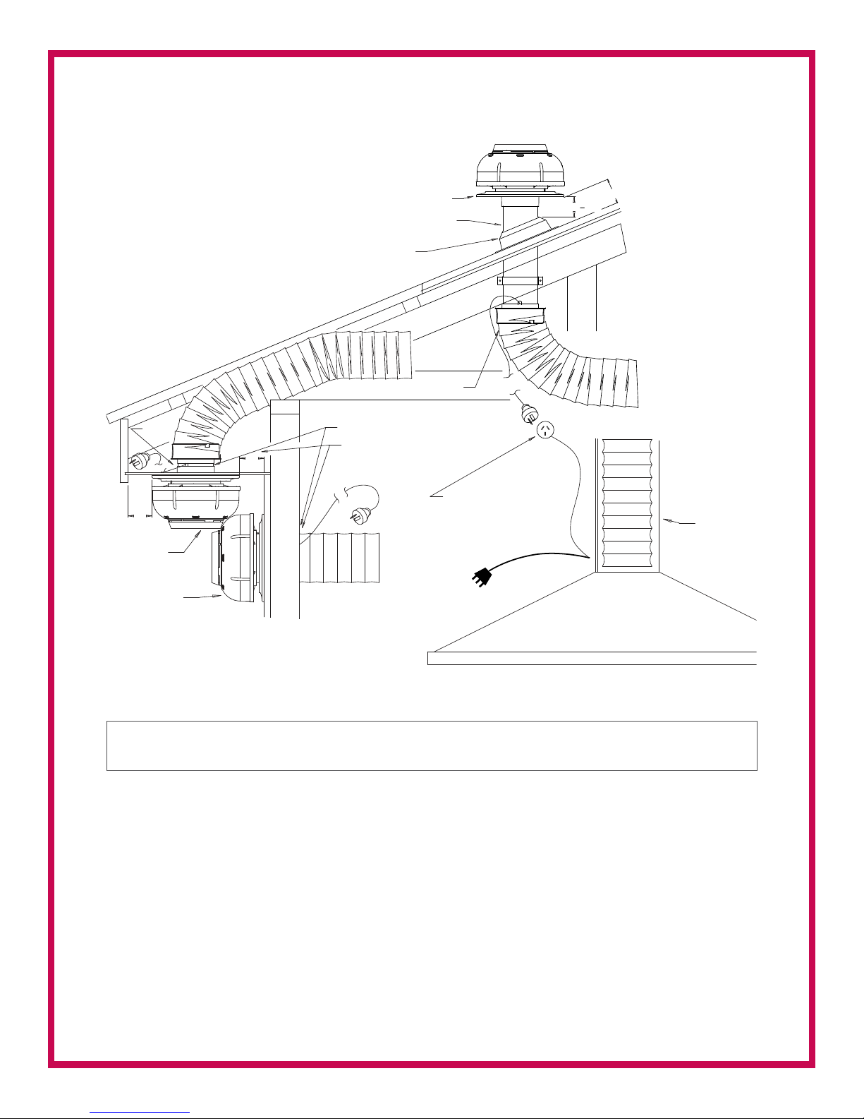
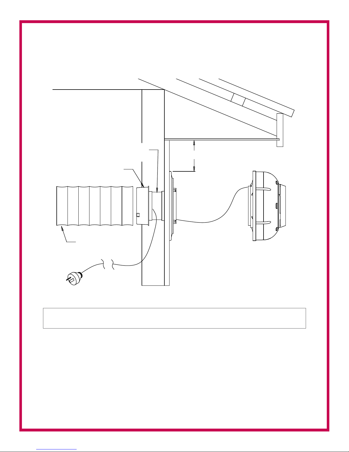
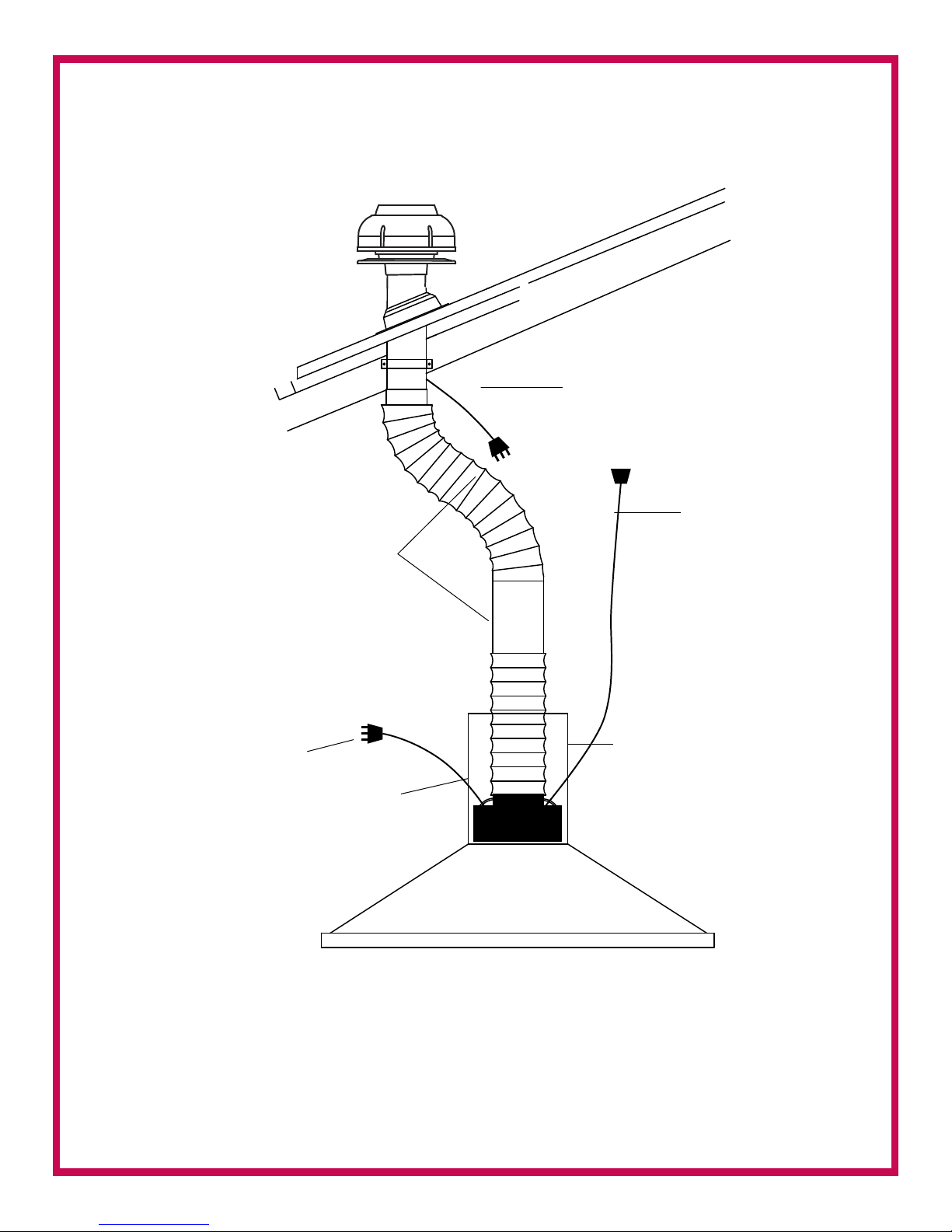
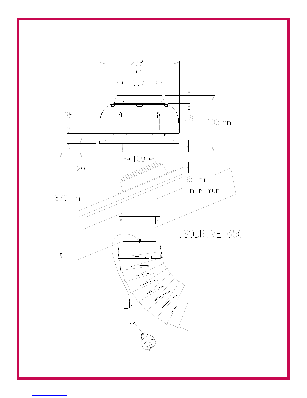
Roof Installation (Recommendedductlength:650motor-3m)
Mountthe100mmrigidPVCpipesecurelytothebeams,trussesorotherappropriatestructures,
refergure1.
Thepipeshouldbemountedeitherverticalorperpendiculartotheroofcladdingwiththeroof
penetrationbeingsealedusingaDektiteorothersealingdevice.
Ensurethatthepipeprotrudesatleast80mmpastthetopoftheDektite,checkingthatthe
mountingangeclearstheroofcladdingatupperedgeasshowningure1.
Maximumrecommendedprotrusionis500mm.Fitmountingange,refergure1,topipeusing
siliconsealant,thentapeinpositionuntilsealanthasset.
Passpowercordandplugthroughmountingangeandpipe,thenouttheslottedPVCpipefor
connectiontothefemaleplugcomingfromthecanopy/rangehoodorauthorizedswitching
mechanisminbathroomapplication.
Fitfanmoduletomountingangebyplacinginposition,rotatingclockwisetoengagebayonet
ngersthensecurebyscrewinginlockingscrew(whileholdingfanmodulermlyinthefully
clockwiseposition).

Page 4
COVER
RANGE HOOD
ELECTRICAL CONNECTION
BETWEEN RANGE HOOD
AND REMOTE FAN MODULE
TO RANGEHOOD
TO RANGEHOOD
CONNECT
CONNECT
TO FAN
DEKTITE
MOUNTING FLANGE
100mm PVC PIPE
80 500
20
20
EAVES MOUNT
OPTION
WALL MOUNT
OPTION
MIN
MIN
ENSURE CLEARANCE
MIN 90mm LONG PVC PIPE
BELL-MOUTH ADAPTOR
BELL-MOUTH ADAPTOR
SLOT
OPTION
ROOF MOUNT OPTION
Figure 1 The three options for mounting the unit.
ForextraFlexibleductinginstructionsrefertoPage8and9.

Page 5
TO RANGEHOOD
CONNECT
5m MAX
POWER CORD
SLOT OPTION
OPTIONAL BEND
SLOT PIPE FOR POWER
CORD EXIT.
COVER WITH DUCT
TAPE IF REQUIRED.
150mm FLEXIBLE DUCT
100 mm SEWER PIPE
BELL-MOUTH ADAPTOR
SECURE PIPE TO STRUCTURE
ROOF FRAME
DEKTITE
MOUNTING FLANGE
ROOF CLADING
FAN MODULE
LOCKING SCREW
Figure 2
TO RANGEHOOD
CONNECT
5m MAX
POWER CORD
SLOT OPTION
OPTIONAL BEND
SLOT PIPE FOR POWER
CORD EXIT.
COVER WITH DUCT
TAPE IF REQUIRED.
150mm FLEXIBLE DUCT
100 mm SEWER PIPE
BELL-MOUTH ADAPTOR
SECURE PIPE TO STRUCTURE
ROOF FRAME
DEKTITE
MOUNTING FLANGE
ROOF CLADING
FAN MODULE
LOCKING SCREW
TO RANGEHOOD
CONNECT
5m MAX
POWER CORD
SLOT OPTION
OPTIONAL BEND
SLOT PIPE FOR POWER
CORD EXIT.
COVER WITH DUCT
TAPE IF REQUIRED.
150mm FLEXIBLE DUCT
100 mm SEWER PIPE
BELL-MOUTH ADAPTOR
SECURE PIPE TO STRUCTURE
ROOF FRAME
DEKTITE
MOUNTING FLANGE
ROOF CLADING
FAN MODULE
LOCKING SCREW
TO RANGEHOOD
CONNECT
5m MAX
POWER CORD
SLOT OPTION
OPTIONAL BEND
SLOT PIPE FOR POWER
CORD EXIT.
COVER WITH DUCT
TAPE IF REQUIRED.
150mm FLEXIBLE DUCT
100 mm SEWER PIPE
BELL-MOUTH ADAPTOR
SECURE PIPE TO STRUCTURE
ROOF FRAME
DEKTITE
MOUNTING FLANGE
ROOF CLADING
FAN MODULE
LOCKING SCREW
ForextraFlexibleductinginstructionsrefertoPage8and9.

Page 6
Afterensuringsufcientclearanceexistsforthemountingangeandducting,refergure1,cuta
circularhole165mmØ,maintainingadequateclearances.Theeavessheetingshouldbereinforced.
Pre-drillmountingangerecess.Refergure3.
Ifaccesstotheeavesspaceisrestricted,beforexingmountingangetoeaves,preassemble
mountingange,PVCpipe,bell-mouthadaptorandexi-ductthenfeedupintoroofspace.
RemembertorunpowercordthroughtheassemblyandouttheslottedPVCpipewall,refergure3.
Fitfanmoduletomountingangebyplacinginposition,rotatingclockwisetoengagebayonet
ngersthensecurebyscrewinginlockingscrew(whileholdingfanmodulermlyinthefully
clockwiseposition).
TOP PLATE
PRE-DRILL MOUNTING
FLANGE RECESS AND
SECURE TO REINFORCED
EAVES SHEET USING
# 8 SELF TAPPING
SCREWS
BELL-MOUTH ADAPTOR
ENSURE THAT ONE OF THE THREE BAYONET
FINGERS IS ACCESSABLE FOR SECURING
LOCKING SCREW
LOCKING SCREW
150mm DUCT
EAVES
ROOF
CLADDING
WALL
ROOF FRAME / TRUSS
Figure 3
ForextraFlexibleductinginstructionsrefertoPage8and9.

Page 7
Wall Installation
Theinstallationshouldbesimilartoeavesmountingifaccesstotheinsideislimited,butif
unrestricted,asmaller120mmductholemaybeusedwiththeductingbeingttedafter
attachmentofthefanmodule.RefertoEAVESINSTALLATIONgure1and4.
NOTE:- ENSURE THAT POWER CORD IS FEED
THROUGH EXIT SLOT AND IS NOT ALLOWED
TO DOUBLE BACK RESTRICTING FAN INLET
20mm
MIN 90mm LONG
PVC PIPE
BELL-MOUTH ADAPTOR
FLEXIBLE 150mm
DUCT
MIN
Figure 4
ForextraFlexibleductinginstructionsrefertoPage8and9.

Page 8
Single Motor Installation Example for 1600 and 650 motor
The motor can be connected using a double adaptor or you may have it wired by an electrician.
Figure 1
Roof mount option (1600 motor)
Roof mount option (650 motor)
Connect to main power
Connect to motor
Computer box
For 650 motor, use reducer
150mm to 200mm
Rangehood
Cover
Use smooth owing curves
for maximum airow.
Remove excess ducting by
trimming to length. DO NOT
install motor in straight line
to rangehood.
Connect to rangehood
SINGLE MOTOR INSTALLATION GUIDE
HOME APPLIANCES
P.O. Box 471 Maylands WA 6051
P: 1300 881 693 F: 1300 881 639
Figure 5
Usereducer150mmto200mm

Page 9
Wheretwomotorsaretobeused,followthebelowmethodsforeachmotorthenjoinintothe
“Y”piecepriortojoiningductingtothecanopy/rangehood.Refergure6.
Thetwomotorscanbewiredbyoneofthefollowingmethods:
• Wiredintooneplugbyanelectrician
• Adoubleadaptorpluggedintotheleadfromthecanopy/rangehood
• AdoubleGPOpoweredfromthecanopy
Figure 6
Cover
“Y”junctionfortwinfaninstallation
canuse150mmx150x150mmor
150x150x200mmdependingon
outletsizeonrangehood
Trytokeeplengthof
exibleductingaseven
apossibleotherwise
motorswilldrawairoff
eachother
Roofmountoption
Roofmountoption
Ensure150mmexible
ductingisfullyextended
andasshortaspossible.
Usesmoothowingcurves
formaximumairow.
Removeexcessductingby
trimmingtolength.
Usereducer150mmto200mm

Page 10
Measurements for Isodrive 650
Friday, August 26, 2011 15:18:13

Page 11
In shallow roof spaces
extend exi pipe horizontally
Installation for Flexi Ducting
2 metres
3 metres
in length
Please keep the
exi pipe taught
Do not crush the exi pipe
mustbefullyextendedandcuttotherequiredlengthuponinstallation.
Maximumfanperformancewillnotbeachievedunlesstheductingisfullyextended.Failureto
fullyextendductingresultsinasmallerairpassageandlowerairows.Incorrectinstallationmay
reduceairoworincreasenoiselevels.Calloutsrelatingtoincorrectinstallationwillresultina
servicefeedirectedtothecustomer.Schweigenwilltakenoresponsibilityforproblemscaused
byfaultyinstallation.Installationshouldbedonebyaqualiedtechnician.Apreferredinstallerlist
canbeobtainedfromschweigenwebsite.
Isodrivemotorhasa10-Yearreplacementproductwarranty.Thisisachangeover
warranty.Theconsumerisresponsibleforanychargesassociatedwithremovalofthe
faultyunitandinstallationofthenewunit.Thecustomerisalsoresponsibleforanyfreight
chargesincurredinthischangeoverprocess.
or
(Seeinsertformoreinformation)
© 2010 Larry Richards. Issue 3, March 2012 R3

Table of contents