ISOMAG MS 1000 User manual

INSTRUCTION MANUAL
MS 1000

START UP AND MAINTENANCE OF THE INSTRUMENTS _____________ 1
INTRODUCTION___________________________________________ 1
SAFETY__________________________________________________ 2
GENERAL INFORMATION ON THE SENSORS INSTALLATION _________ 2
OVERALL DIMENSIONS _____________________________________ 3
OPERATING TEMPERATURES _________________________________ 4
ELECTRICAL CONNECTIONS OF SENSOR TO CONVERTER ___________ 5
GROUNDING INSTRUCTIONS ________________________________ 6
TORQUES (NM) FOR WAFER SENSOR’S BOLTS ___________________ 7
NOTES FOR PED DIRECTIVE FOR SENSOR ______________________ 8
DECLARATION OF CONFORMITY TO EUROPEAN
DIRECTIVE PED – 97/23/CE _________________________________ 9

1
MS1000 – SENSOR MANUAL
1000_EN_IT_IS_R0_PED
INTRODUCTION
– This manual is integral part of the product. Read carefully the instructions contained since
it contains important indications for the safety of use and of maintenance.
– The technical information and the relative products of this manual could be modied
without any previous notice.
– The ow meter must be used for the use it has been built for. The improper use, possible
tampering of the instrument or parts of it and substitutions of any components not original,
makes the warranty to decay automatically.
– The manufacturer is considered responsible only if the instrument is used in its original
conguration and setting.
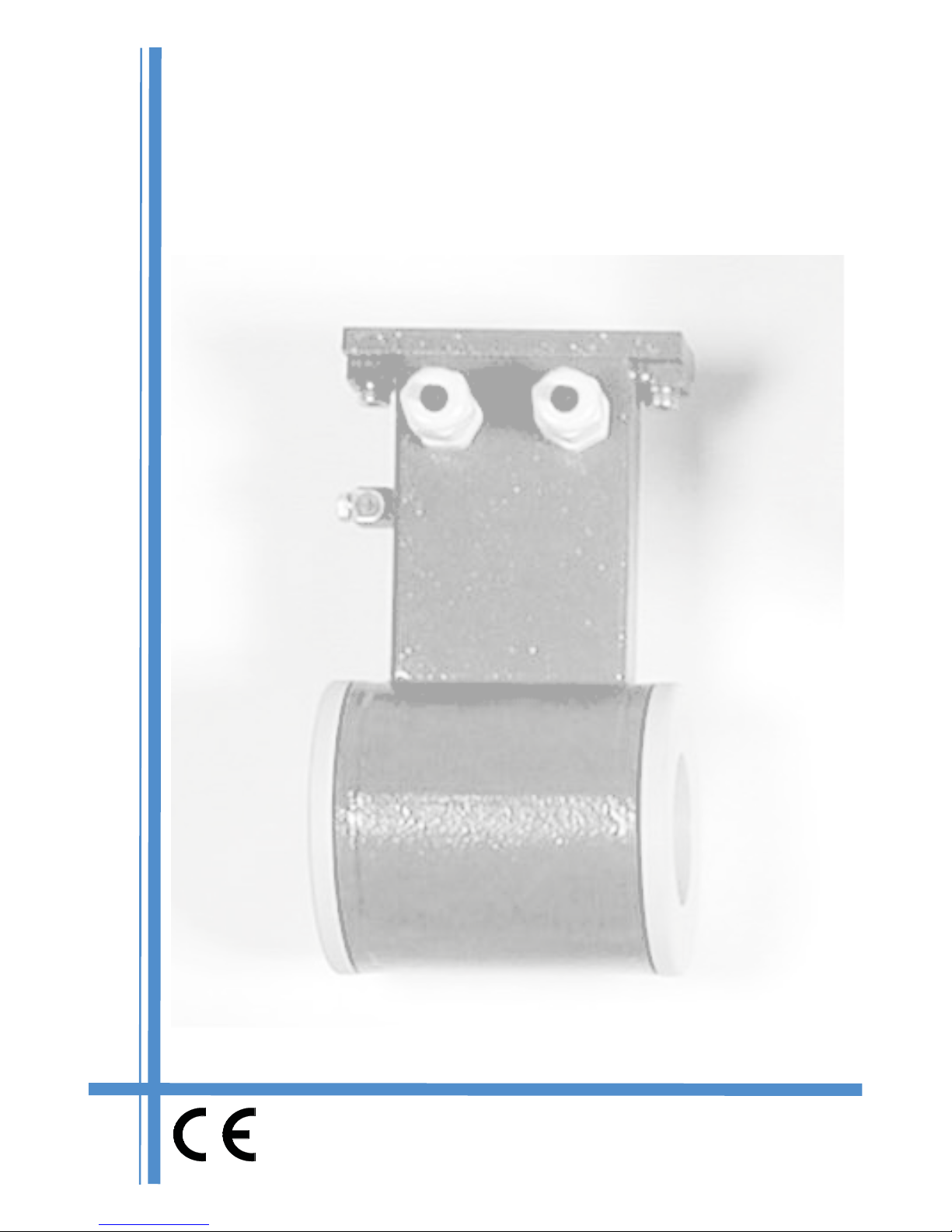
– The owmeter makes measures of liquids with conductivity greater than 5µS/cm; it consists
of a sensor (described in this manual) and a converter, for it see the manual provided.
– If the sensor is supplied in compact version to the converter, consider the operating
temperatures more restrictive, otherwise refer to the respective manuals (page 5).).
– When transporting, unpacking and handling the owmeter, be careful and care.
– In the case of prolonged storage and of transport, use and store in the original container
in a dry place, do not place more than 3 packs one above the other.
– It is possible pallets storage and transport (in case of wooden crates do not place one
above the other).
– For the cleaning of the device use only a damp cloth, and for the maintenance/repairs,
contact the customer service.
– For the disposal of the device and of the packaging make strict reference to the regulations
– It is forbidden the reproduction of the present manual and of possible software supplied
with the instrument.
START UP AND MAINTENANCE OF THE INSTRUMENTS
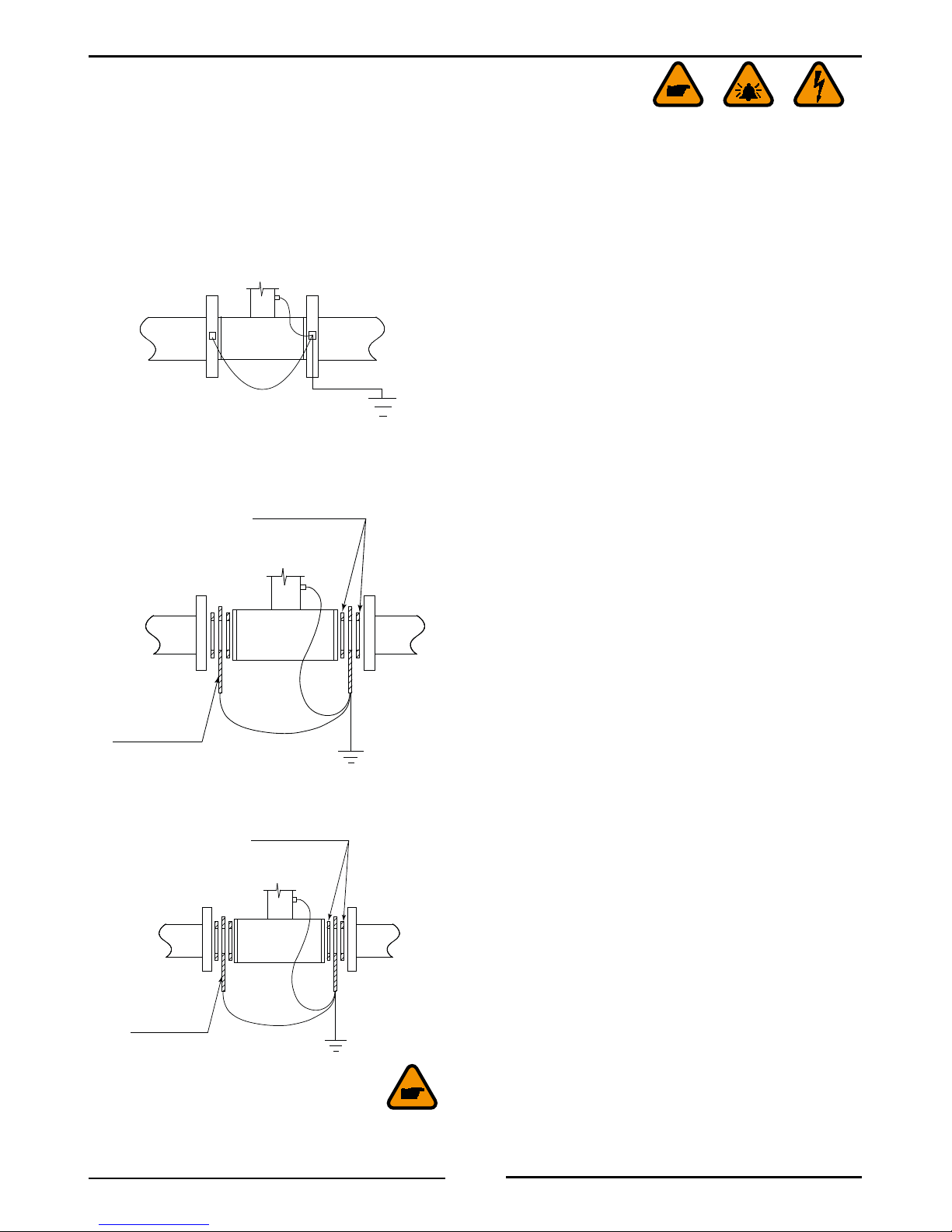
– Before starting up the instrument, always make a sure connection to ground as suitable
to page 6.
– Verify periodically: the cables integrity, the tightening of the sealing elements (cable glands,
covers, etc.), the mechanical xing of the instrument on the pipe or on the wall stand

2
MS1000 – SENSOR MANUAL
1000_EN_IT_IS_R0_PED
Before using the instrument, always make a sure connection to the ground
Avoid any attempt to repair the instrument. If the instrument is not
functioning properly, please call the nearest assistance service
Pay maximum attention during the operations
ATTENTION !!!
DANGER !!!
SAFETY
GENERAL INFORMATION ON THE SENSORS INSTALLATION
Lifting sensors
The sensors with eyebolts must be
lifted by the method shown below.
The eye-bolt are measured to sustain
exclusively the weight of the meter
?
-
+
Before install the sensor locate the
direction of the liquid in the piping
The sign of the ow rate is positive,
when the ow direction is from – to +
as printed on the tag plate.
If after the installation, for plant request
becomes necessary reverse the sign of
the ow, it is enough reverse the sign
of the coefcient KA
fLow direction
Centring cylinders

3
MS1000 – SENSOR MANUAL
1000_EN_IT_IS_R0_PED
OVERALL DIMENSIONS
DN
G
L
D
H
70
25
mm
(inches)
DN
25
(1”)
32
(1” 1/4)
40
(1” 1/2)
50
(2”)
65
(2” 1/2)
80
(3”)
100
(4”)
125
(5”)
150
(6”)
200
(8”)
250
(10”)
300
(12”)
350
(14”)
400
(16”)
L
+0 +0 +0 +0 +0 +0 +0 +0 +0 +0 +0 +0 +0 +0
-3
(-0.12)
-3
(-0.12)
-3
(-0.12)
-3
(-0.12)
-3
(-0.12)
-3
(-0.12)
-3
(-0.12)
-3
(-0.12)
-3
(-0.12)
-3
(-0.12)
-5
(-0.20)
-5
(-0.20)
-5
(-0.20)
-5
(-0.20)
100
(3.94)
100
(3.94)
100
(3.94)
100
(3.94)
150
(5.90)
150
(5.90)
150
(5.90)
180
(7.09)
180
(7.09)
200
(7.87)
250
(9.84)
300
(11.81)
350
(13.78)
400
(15.75)
H147
(5.79)
153
(6.02)
161
(6.34)
177
(6.97)
199
(7.83)
209
(8.23)
235
(9.25)
263
(10.35)
291
(11.46)
362
(14.25)
417
(16.42)
467
(18.39)
527
(20.75)
579
(22.80)
D62
(2.20)
67
(2.44)
78
(2.76)
92
(3.39)
108
(4.25)
118
(4.65)
144
(5.67)
172
(6.77)
200
(7.87)
271
(10.67)
326
(12.83)
376
(14.80)
436
(17.17)
488
(19.21)
G- - - - - - - - - 144
(5.67)
194
(7.64)
244
(9.60)
294
(11.57)
344
(13.54)
Weight
kg (lbs)
1.2
(2.64)
1.6
(3.52)
1.8
(3.96)
2
(4.4)
3.6
(7.92)
3.8
(8.36)
5
(11)
7.8
(17.16)
8.2
(18)
18.2
(40)
24
(53)
27
(59)
32
(70)
39
(86)
Usable
anges
PTFE-EBONITE: PN10, PN16, PN25, PN40, ANSI150, ANSI,300 PP: PN10,
PN16, ANSI150 PTFE-EBONITE: PN10, PN16, ANSI150

4
MS1000 – SENSOR MANUAL
1000_EN_IT_IS_R0_PED
shrewdness and Precautions
NO YES
OPERATING TEMPERATURES
EBONITE LINING PP LINING PTFE LINING
Liquid
temperature
Ambient
temperature
Liquid
temperature
Ambient
temperature
Liquid
temperature
Ambient
temperature
Min. Max Min. Max Min. Max Min. Max Min. Max Min. Max
°C 0 80 -5 60 0 60 0 60 -20 130 -10 60
°F 30 176 23 140 32 140 32 140 -4 266 14 140
LONG PIPE
LONG PIPE
ANTI VIBRATION JOINTS
3 DN 2 DN
GASKET THICKNESS +4mm
For vertical installations
with descending ow
direction contact the
manufacturer
Avoid the installation of
the sensor in a long pipe
line,without any support
of the same
Avoid the functioning
with the pipe partially
empty
Avoid the installation
near curves or hydraulic
accessories
Avoid the approach of
the ange and counter
ange using the closing
force of the nuts
For vertical installations is
preferable an ascending
ow
For installations on long
pipe line, please use the
anti vibration joints
During the functioning the
pipe must be completely
full of liquid, or completely
empty
Install the sensor away
from curves and hydraulic
accessories
Before tightening the nuts
approach as more possible
the ange of the piping to
the ange of the sensor

5
MS1000 – SENSOR MANUAL
1000_EN_IT_IS_R0_PED
ELECTRICAL CONNECTIONS OF SENSOR TO CONVERTER
connections to converter: see ProPer manuaL
VERSION SUITABLE FOR SENSOR’S
CONNECTION
COMPACT ALL SENSORS MODEL NO CONNECTIONS
SEPARATE WITHOUT
JUNCTIONS-BOX STAINLESS STEEL MODEL
NO CONNECTIONS REQUIRED
(CABLE ALREADY CONNECTED
AND POTTED)
SEPARATE WITH JUNCTIONS-
BOX
(WITH OR WITHOUT
PREAMPLIFIER)
ALL CARBON STEEL MODELS
NO CONNECTIONS REQUIRED
(CABLE ALREADY CONNECTED
AND POTTED)
SEPARATE WITH
PREAMPLIFIER ALL STAINLESS STEEL MODEL
NO CONNECTIONS REQUIRED
(CABLE ALREADY CONNECTED
AND POTTED)

6
MS1000 – SENSOR MANUAL
1000_EN_IT_IS_R0_PED
GROUNDING INSTRUCTIONS
For correct operation of the meter is NECESSARY that the sensor and the liquid are equipotential,
so ALWAYS connect the sensor and converter to ground:
grounding with metaLLic PiPe
grounding with insuLating PiPe
grounding when there is acathodic Protection over the PiPe
INSULATING GASKET
METALLIC RING
If the sensor must be install in the piping with a
cathodic protection, is necessary:
• using insulating bushes to isolate the bolts
• Grounding metallic rings should be provided
to ground the liquid using insulating gasket
between the rings
IMPORTANT: The ripple of DC power source
used for cathodic protection shall be = 0
INSULATING GASKET
METALLIC RING
If the sensor has to be mounted on a pipe made of
an insulating materials necessary:
• Install two metallic ring between the sensor
anges and the counter anges of the pipe line
or
• Use a sensor with the additional grounding
electrode

7
MS1000 – SENSOR MANUAL
1000_EN_IT_IS_R0_PED
TORQUES (NM) FOR WAFER SENSOR’S BOLTS
OPERATIVE PRESSURE
Kpa 1600 4000
psi 260 600
DN EBON. PP PTFE
25 19 25
[32]
32 28 43
[40]
40 36 53
[63]
50 52 68
[35]
65 75 45
[53]
80 41 53
[68]
100 56 83
[94]
125 71 112
[130]
150 106 135
[113]
200 288
(433)
250 408
(455)
300 510
(683)
350 598
(946)
400 821
(911)
• Tighten uniformly in diagonally opposite sequence
• The torque listed in tab are applicable to anges: EN1092-1, DIN2501, BS4504, ANSI
B16.5, JIS
• Is recommended the use of gaskets DIN 2690
• (***)= FOR SENSORS ON ANSI 150 FLANGES
• [***]= FOR SENSORS ANSI 300 FLANGES

8
MS1000 – SENSOR MANUAL
1000_EN_IT_IS_R0_PED
NOTES FOR PED DIRECTIVE FOR SENSOR
Here below the tables of products subject to Directive 97/23/EC.
The models are : MS1000/MS2410/MS2500.
The tables show which category of PED is applicable according to the water operating
temperature (TAB A T <110 ° C TAB B T> = 110 ° C), sensor’s DN and its nominal pressure.
DN NOMINAL PRESSURE (PN)
10 16 25 40
25
USE PN 40
E
32 E
40 E
50
USE
PN 16
E
USE
PN 40
E
65 E E
80 E E
100 E E
125 E E
150 E E
200 EEEE
250 IIII
300 IIII
350 IIII
400 IIII
450 IIII
500 IIII
600 IIII
700 IIII
800 IIII
900 IIII
1000 IIII
1200 IIII
1300 IIII
1400 IIII
1500 IIII
1600 IIII
1700 IIII
1800 IIII
2000 IIII
2400 IIII
tab. a
Ped directive for water with
temPerature <110°c
aLL Lining : PP, ebonite,Ptfe
DN NOMINAL PRESSURE (PN)
10 16 25 40
25
USE PN 40
E
32 E
40 II
50
USE
PN 16
I
USE
PN 40
II
65 I II
80 I II
100 I II
125 I II
150 I II
200 I I II II
250 I II II II
300 I II III III
350 I III III III
400 II III III III
450 II III III III
500 II III III III
tab. b
Ped directive for water with
temPerature >=110°c
onLy Ptfe Lining
Legenda
E OUT OF DIRECTIVE
I PED CAT. I
II PED CAT. II
III PED CAT. III
For products that falls in category I, is valid the declaration of conformity available on the
following page; the products in Category II and III are supplied with a specic declaration of
conformity for each instrument

9
MS1000 – SENSOR MANUAL
1000_EN_IT_IS_R0_PED
DECLARATION OF CONFORMITY TO EUROPEAN
DIRECTIVE PED – 97/23/CE
Prepared in accordance with Annex VII Legislative Decree no. 93 of 25 February 2000
transposing Directive no. 97/23/EC
Description of the
product
Misuratore di portata di liquidi del gruppo 2
Temperatura massima del liquido 110°C
Model family MS 2500 – MS1000 – MS2410
Conformity assessment
procedure applied Allegato II - categoria I - Modulo A
Standard reference UNI EN 13480-3
Hemina declares that the equipment specied above model should fall within the scope
of the Directive, are:
¾comply with the requirements of Directive 97/23/EC - PED and DL 93/2000 which
transposes in Italy
Identication and signature of the legal representative:
Roberto Guazzoni – President of Board of Directors

Service
Isoil Industria spa
20092 Cinisello Balsamo (MI) Italy
27, via F.lli Gracchi
Phone +39-02-66027.1
Fax +39-02-6123202
E-mail: [email protected]
Isoil Industria spa
Head ofce
20092 Cinisello Balsamo (MI) Italy
27, via F.lli Gracchi
Phone +39-02-66027.1
Fax +39-02-6123202
E-mail: [email protected]
Web: www.isoil.com
Table of contents
Other ISOMAG Measuring Instrument manuals