Isotra MIRA 4 User manual

This manual is valid from 1 May 2018 1
MEASUREMENT AND ASSEMBLY MANUAL
MIRA 4, MIRA 2 PERGOLAS
MEASUREMENT
AT MIRA PERGOLAS WE ALWAYS MEASURE THE OUTER CASING OF THE CONSTRUCTION. WE ENTER
TOTAL WIDTH, TOTAL HEIGHT (EXTENSION) AND DIMENSION H (SUB-HEIGHT OF THE SYSTEM).
ATTENTION! TOTAL HEIGHT OF THE SYSTEM WILL ALWAYS BE 200 MM HIGHER THAN YOUR
ORDERED SUB-HEIGHT. FURTHERMORE, IT IS NECESSARY TO COUNT WITH FUNCTIONALITY OF
THE SLATS WHERE THE TOTAL HEIGHT OF THE PERGOLA CAN BE INCREASED BY 110 MM AT 90 °
OPENING CONDITION.
IT IS ALSO NECESSARY TO SPECIFY FURTHER OPTIONAL ACCESSORIES, SUCH AS LIGHTING, ANTI-
SNOW SYSTEM, RAIN AND TEMPERATURE SENSOR. IT IS ALSO APPROPRIATE TO SPECIFY
BUILDING READINESS FOR SUBSEQUENT INSTALLATION OF THE ENTIRE PERGOLA SYSTEM
(ANCHOR POINTS, WATER DRAINS, WIRING, ETC.)

This manual is valid from 1 May 2018 2
MEASUREMENT AND ASSEMBLY MANUAL
1. INTRODUCTION
PRIOR TO INSTALLING MIRA 4, MIRA 2 PERGOLAS, READ THIS MEASUREMENT AND INSTALLATION
MANUAL CAREFULLY. THIS STRUCTURE HAS BEEN DESIGNED SOLELY AS PROTECTION FROM SUN,
RAIN, AND WIND, AND CANNOT BE CONSIDERED WATER-TIGHT.
INCORRECT USE OR INSTALLATION SHALL RESULT IN THE TERMINATION OF THE GUARANTEE.
IN THE CASE OF SNOWFALL, OPEN THE SLATS TO VERTICAL POSITION.
The pole anchoring must be specified on site according to the type of wall and floor. Various circumstances must
be considered: conditions, texture, surface strength and appearance. Do not use washers and bolts whose
properties are inferior to those specified in this manual.
2. LIST OF NECESSARY TOOLS
▪Two ladders adjustable according to the pergola height, telescopic lifting appliance;
▪Socket-wrench set, Allen keys, spanners size 10, 17, 13 –2 pc (one with very thin head –for louvre
tightening);
▪Flat-blade screwdriver, PH2 Philips-head screwdriver;
▪Adhesive tape –for attaching the pole covers and covering the water drains (prevents falling of the fastening
bolt into the poles) –remove the tape just before inserting the drain pipe 2.12;
▪Transparent silicone caulk.
front
guide
slat
motor
slotted plate
back

This manual is valid from 1 May 2018 3
MEASUREMENT AND ASSEMBLY MANUAL
3. INSTALLATION INSTRUCTIONS
3.1 POSITIONING THE POLES
Place the poles on the ground according to the pergola dimensions specified in the data sheet.
PRIOR TO INSTALLATION, INSERT NECESSARY PLATES WITH M8 THREAD TO EACH PROFILE.
SEE THE SUPPLIED SKETCH.
The poles (2.1) are equipped with adjustable feet (2.2) that compensate for any undulations. Set them up
according to dimensions specified in the data sheet. Adjust using M10×60 hexagonal-head bolts (2.3).
For MIRA 2, place the consoles to the wall (2.4) and secure by M10 bolts according to dimensions specified in
the data sheet.
3.2 ATTACHING THE UPPER PROFILES
It is recommended to begin the installation with the front upper profile and two poles, continuing with
one side upper profile and a pole, and then with the remaining upper profiles and the last pole. DO NOT
FORGET TO SLIDE THE LOWER POLE COVERS 6.1 TO THE POLES.
Place the peripheral upper profiles (2.5) to the poles. Pay attention to their matching and placing to the corner
gasket (2.6).
ADJUSTABLE FOOT
R610 WALL ATTACHMENT
GASKET

This manual is valid from 1 May 2018 4
MEASUREMENT AND ASSEMBLY MANUAL
Remember that there are two versions of the side upper profiles, one of them with a motor already installed. The
back and front profiles can be identified by the installed upper cover –profile (2.7).
Place the connection plate (2.8) to this place and insert six M10×45 hexagonal-head bolts, leaving them loose.
Perform this operation in all corners of the structure. The connection plate gasket must be headed down.
THE GASKET MUST HEAD
DOWN
BACK
FRONT

This manual is valid from 1 May 2018 5
MEASUREMENT AND ASSEMBLY MANUAL
Fasten the structure using the pre-installed corner connection elements (2.9) on the water drain profile using
M8×30 hexagonal-head bolts and nuts (2.10).
Tighten each corner using the connection elements, while compressing the corner gaskets.
Then tighten all connection plates by six M10×45 hexagonal-head bolts on each pole (2.11).
Insert the 50 mm drain pipe (2.12) to the openings in the water drain profile, while applying silicone to the collar
(adjust the collar direction according to the picture).
3.3 MOTOR DRIVE
The motor (3.1) is present in all versions and is pre-installed in the correct position, but later on, it may be
necessary to adjust its position due to safe louvre closing (see 5.2).
Front
THE GASKET WILL BE
HEADED DOWN
Side guide rail
APPLY SILICONE
MOTOR CONNECTION
Front

This manual is valid from 1 May 2018 6
MEASUREMENT AND ASSEMBLY MANUAL
If two motors are used, pay attention to correct connection of the control unit. NEVER START THE DEVICE
WITHOUT PREVIOUS WIRING TEST!
CAUTION: IN PERGOLAS WITH TWO MOTORS, PAY ATTENTION TO THE DIRECTION OF MOVEMENT
(UP/DOWN).
CONNECTING MOTORS IN THE WRONG DIRECTION CAN CAUSE IRREVERSIBLE DAMAGE.
Front
THE PICTURE SHOW LATERAL RIGHT INSTALLATION
FRONT
MOTOR 1
ALWAYS PRESENT
MOTOR 2
(IF PRESENT)
BACK

This manual is valid from 1 May 2018 7
MEASUREMENT AND ASSEMBLY MANUAL
3.4 ATTACHING THE SLATS
Insert the individual slats to the corresponding lateral housing (4.1); first on the motor side (there are two pins
on the slat side) and then on the opposite side. Each slat overlaps the next one. Then fasten each slat using M6
hexagonal-head bolts with washers and spacers for each side pin (4.2). (Remove one spacer, or the other,
depending on the installation tolerances.)
Insert the M8 hexagonal nuts with washers, but leave them loose (4.3) (THEY ARE TO BE TIGHTENED LATER
AS PART OF THE ADJUSTMENT).
3.5 SLATS CLOSING, AND MOTOR ADJUSTMENT
Once all the slats are installed, adjust their closing and the motor thrust and test their opening and closing (see
Section 7). Then insert 14 cm wooden spacers (5.1) under the slats in closed position, thus facilitating their
adjustment and correct levelling. Tighten the M8 nuts in their correct position in the oval slots of the carrier
connecting plate. REMOVE THE SPACERS!
CAUTION, RISK OF HAND INJURY!

This manual is valid from 1 May 2018 8
MEASUREMENT AND ASSEMBLY MANUAL
Test the motor at the max. closing and opening end stop (see Section 7). If necessary, adjust the motor thrust
using the nuts and M8 motor adjusting screws (5.2) by sliding to the sides.
CAUTION! DO NOT EXCESSIVELY PRELOAD THE SLAT CLOSING.
Once the motor has been positioned, fully tighten the M8 adjusting screws and M8 nuts. If necessary, repeat
the adjustment. Correct slat calibration ensures sufficient applied to each gasket (5.3).
ATTENTION: IN CASE OF TWO MOTORS, BOTH MUST GET THE END STOP IN THE SAME TIME.
MOTOR THRUST ADJUSTMENT

This manual is valid from 1 May 2018 9
MEASUREMENT AND ASSEMBLY MANUAL
3.6 INSTALLATION OF COVERS
Following a re-check of the structure horizontality, fasten the feet to the ground with the corresponding fasteners
and set the pole covers 6.1 to the lower position.
Then install the upper covers of the roof profiles and fasten them using self-drilling screw 3.9×19 (6.3).
3.7 WIRING AND ADJUSTMENT OF THE CONTROL UNIT
POWER SUPPLY 230 V /
24 V IP 67
REMOTE
CONTROLLER WITH
7 FUNCTIONS
LINEAR MOTOR
CONTROL UNIT

This manual is valid from 1 May 2018 10
MEASUREMENT AND ASSEMBLY MANUAL
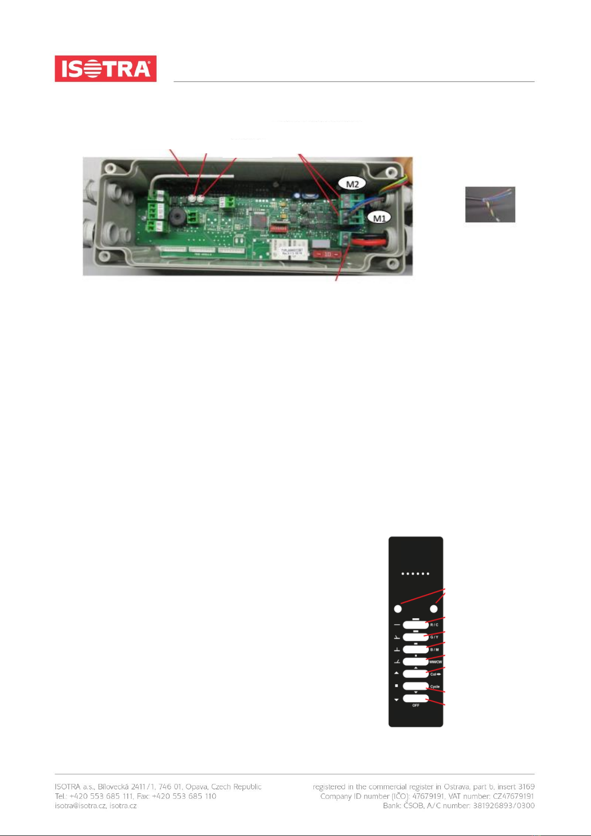
3.7.1 CONTROL UNIT ADJUSTMENT
The control unit beeps intermittently upon first start-up.
Press the P1 (close) and P2 (open) buttons to activate the motor. Use the P1 and P2 buttons to move the slats
from fully open position to closed position. BE CAREFUL DURING THE MOVEMENT (RISK OF INJURY).
3.7.2 END STOP AUTOMATIC SETTING
Press the P1 a P2 buttons simultaneously for a short time (0.5 s), then hold again for 5 seconds.
The system will automatically run two cycles of slat opening closing, searching for the end stops. The
remote controller channel has already been programmed and will only work after the end stop automatic
setting.
To reset the end stops, press the P1 a P2 buttons simultaneously for 5 seconds.
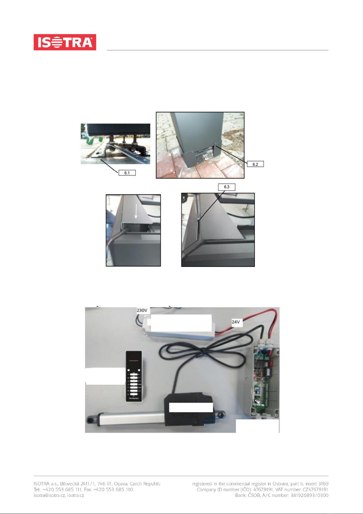
Install the control unit and the power unit to a place protected from the rain and standing water (for instance, to
the front of the structure under the cover) or to a water-tight box.
3.7.3 REMOTE CONTROL MEMORY
(ONLY FOR SLATS, NOT FOR LED)
Press the P1 button shortly (0.5 s) and then again, holding it pressed.
3.7.4 DELETING THE REMOTE CONTROL
(ONLY FOR SLATS, NOT FOR LED)
You can delete the remote control by pressing the P1 button five times
(0.5 s), holding it the sixth time longer (the control unit starts beeping).
Then the control unit emits a long beep that signals successful deletion.
ANTENNA
BUTTON 1
BUTTON 2
MOT. M1 3-BROWN 4-BLUE
MOT. M2 (IF INSTALLED) 5-BROWN 6-BLUE
(PAY ATTENTION TO CORRECT WIRING)
POWER SUPPLY 24 v 1-RED 2-BLACK
CHANNEL SELECTION
CH 1 –SLATS OPENING
CH 2 –OPENING TO 26 %
CH 3 –OPENING TO 66 %
CH 4 –OPENING TO 100 %
CH 5 –MANUAL OPENING
CH 6 –STOP
CH 7 –MANUAL CLOSING

This manual is valid from 1 May 2018 11
MEASUREMENT AND ASSEMBLY MANUAL
3.8 ACCESSORIES AND SENSORS
CAUTION! The electronic card is protected by a 10 A fuse. The max. allowed
power input incl. the LED card is 240 W.
POWER INPUT 150 W, INPUT 100–240 VAC, 1.7 A, 50/60 Hz
A 277 VAC, 0.7 A
OUTPUT +24 V, 6.3 A
POWER INPUT 240 W, INPUT 100–240 VAC, 4 A,
50/60 Hz
A 277 VAC, 1.2 A
1
POWER SUPPLY (+24 VDC)
2
POWER SUPPLY (GROUND)
3
MOTOR (OPEN)
4
MOTOR (CLOSE)
5
MOTOR (CLOSE)
6
MOTOR (OPEN)
9
RAIN SENSOR (WHITE, +12 VDC)
10
RAIN SENSOR (BLUE, SIGNAL)
11
RAIN SENSOR (YELLOW, GROUND)
12
RF ANTENNA
13
ANTENNA GROUND
14
TEMPERATURE SENSOR (BLACK)
15
TEMPERATURE SENSOR (WHITE)
DIP
MEANING
1-2-3
Wind sensor threshold setting (Section 4.1, page 11)
4-5
Motor control mode (page 4/7)
6
Setting of the motor max. current during configuration
(Section 2.4, page 7)
LED
COLOUR
STATUS
MEANING
L1
RED
ON until next passage
M1: excessive current or end stop was reached
L2
RED
ON until next passage
M2: excessive current or end stop was reached
L3
BLUE
ON
Command mode is synchronised
One flash every second
Command mode is synchronised (during configuration)
One flash every 2 seconds
Command mode is independent (during configuration)
L4
RED
One flash every 10 seconds
Alarm –rain draining (Section 4.4, page 12)
Two fast flashes every 10 seconds
Alarm –rain (Section 4.4, page 12)
Three fast flashes every 10 seconds
Alarm –ice/snow (Section 4.2–4.3, page 11–12)
Six fast flashes
Activation of the end stop contained in the motor
Seven fast flashes
Activation of the end stop due to excessive motor consumption
Eight fast flashes
Safety end stop
Ten fast flashes
One motor is short-circuited
One flash every 2 seconds
Rain sensor is deactivated
One flash every 3 seconds
Temperature sensor is deactivated
L5
RED
ON
Power input is still ON

This manual is valid from 1 May 2018 12
MEASUREMENT AND ASSEMBLY MANUAL
LED LIGHTS BUILT INTO SLATS
To assemble slats with LED lights, install the structure as indicated above, carefully setting the lit slats in the
correct position. Insert the main cable with plug and play connectors inside the lateral frame and connect each
slat carrying a row of lights in correspondence of each bushing. Lock each slat’s pivot pin with a lock ring. The
main cable should be connected directly to the additional light board (placed in the control unit) by means of the
supplied red and black cable. The remote control channel for light modulation is pre-programmed.
In order to store another 7-channel remote controller, proceed as follows:
▪Press the P2 button and keep it pressed until you hear a beep and then, a continuous sound.
▪During the continuous sound, press any button on the indicated channel.
▪Successful saving is indicated by quick beeps.
▪To delete all remote controls, press the P3 button with one single pulse (0.5 sec) and then keep it
pressed until cancellation indicated by a continuous sound.
Rain sensor
The alarm activates when the sensor detects rain. The device moves the slats of the pergola to a closed position.
The device will not perform any controls as long as the alarm conditions last. The alarm will deactivate after the
sensor has not detected any rain for 20 seconds. The sensor is activated as default.
System activity after the rain alarm (rain water draining)
Once the rain alarm has ended, the control unit will open the slats of the pergola to 33% to allow for the draining
of the accumulated rain water and hold for the 6 hours after receiving the automatic movement command from
the transmitter. The control unit will only perform manual command for 4 minutes, thus ending the alarm
conditions.
Rain sensor activation/deactivation from the transmitter
This process requires the use of an already stored transmitter (Art. 3) and must be performed when the device
is in the stop position. The sensor is activated as default.
LED CONNECTION: RED -> BROWN

This manual is valid from 1 May 2018 13
MEASUREMENT AND ASSEMBLY MANUAL
Temperature sensor
The temperature sensor (NTC 10K/3435K) activates whenever there is risk of ice formation. If the temperature
drops below 2 °C, alarm is activated and the control unit opens the slats of the pergola to 66%. The alarm
deactivates once the temperature exceeds 3 °C.
The control unit will only perform manual commands during the alarm and will return to normal operation once
the alarm is deactivated. The sensor is deactivated as default.
Temperature sensor activation/deactivation
Activation (only possible when the sensor is
connected)
▪Press the P1 button 7 times, holding is
pressed for 5 seconds on the seventh press.
▪The buzzer will emit a continuous sound for 4
seconds.
Deactivation
▪Press the P1 button 7 times, holding is
pressed for 5 seconds on the seventh press.
▪The buzzer will emit two beeps.
Activation
Press the STOP button on the transmitter for 10
seconds. The buzzer will emit a continuous
sound for 4 seconds.
Deactivation
Press the STOP button on the transmitter for 10
seconds. The buzzer will emit 2 beeps.

This manual is valid from 1 May 2018 14
MEASUREMENT AND ASSEMBLY MANUAL
ATTENTION
PLEASE NOTE THAT ANY AND ALL COMPLAINTS REGARDING
THE COMPONENTS AND/OR FABRICS MUST BE FILED
IMMEDIATELY AFTER UNPACKING, AND NOT AFTER
INSTALLATION.
This manual suits for next models
1
Table of contents
Popular Tent manuals by other brands

ShelterLogic
ShelterLogic AccelaFrame installation instructions

Outsunny
Outsunny A20-262 manual

Tentipi
Tentipi Half inner-tent Assembling manual

Rubicon Expedition Products
Rubicon Expedition Products Hitch Tent manual

Boutique Camping
Boutique Camping ADVENTURE ATTACHING YOUR TENT PROTECTOR instruction manual

Palram
Palram Juniper 3x3 manual