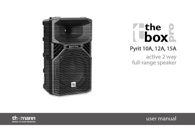
iSP HDL 2208 User manual


IMPORTANT SAFTEY INSTRUCTIONS!
Please read this very carefully before operating this unit
Read ALL instructions carefully before using this unit.
Do not operate this unit near water, in the rain or where there is moisture.
If this warning is ignored a serious electrical shock or death may occur.
Do not attempt to service this unit. No user serviceable parts inside. Refer
servicing to qualified, ISP approved service personnel.
Never remove or defeat the ground connection on the power cord of this
unit.
Care should be taken to avoid spilling any foreign objects or liquid into this
unit.
This active speaker system has a three-channel internal power amplifier
with a heatsink and a fan located inside the speaker for cooling. Air is
drawn in the front grille and hot air is exhausted out the rear of the cabinet.
Care should be taken to avoid placing this active speaker in a location
where the rear exhaust ports are obstructed and does not allow proper
cooling of the internal amplifiers. Avoid placing this system close to other
heat sources. The internal heatsink may reach high temperatures under
normal use. Make certain there is proper ventilation for the speaker when in
use.
Do not drive the HIGH DEFINITION LINE 2208 into excessive heavy
distortion for an extended period of time to avoid premature speaker failure.
Failure to follow these instructions may void the warranty.

Caution: Exposure to extremely high noise levels can
cause permanent hearing loss.
The HIGH DEFINITION LINE 2208 system is capable of producing in excess of 134db SPL
at 1 meter. Continued exposure to noise levels in excess of 90db may cause permanent
hearing loss. Below is a chart of the OSHA (Occupational Safety & Health Administration)
regulations for Occupational Noise Exposure. Please note: OSHA requires hearing
protection for any work environment when the sound levels exceed those shown in Table
G-16 when measured on the A scale of a standard sound level meter at slow response.
INTRODUCTION
Thank you for purchasing ISP Technologies HIGH DEFINITION LINE 2208 active speaker
system. The HIGH DEFINITION LINE 2208 is a high output two-way active speaker
system designed to deliver HI-FI sound quality for high SPL sound reinforcement
applications. ISP Technologies HDL 2208 is a high performance, powered, small-format
line array cabinet providing high fidelity performance and smooth, accurate response.
The HDL 2208 provides a 2-way line array design with little compromise in terms of its mid-
range performance. This is, in part, due to a new high performance non-metallic
compression driver on a multiple-aperture waveguide and dual 8-inch neo woofers. The
result is a new level of performance in a small-format line array system. The HDL 2208 is
a 10-degree vertical by 100-degree horizontal box with user adjustable pin-
points for various splay angles from 1 to 10 degrees in 1 degree increments.
The internal amplifiers are based on ISP Technologies patent pending D-CAT (Dynamic
Current Amplifier Technology) amplifier technology. The D-CAT technology is capable of
delivering extremely high output current providing an improvement in transient response,
output current and a noticeable improvement in PUNCH. The D-CAT amplifier technology
utilizes a high performance power amplifier driver that reduces parts count and greatly
improves reliability. The D-CAT amplifiers provide improved reliability by including short
circuit and over temperature protection.
The HIGH DEFINITION LINE 2208 cabinet is made of high quality 13 ply Baltic birch
plywood built with smooth sides, the boxes provide a very clean look, without any
protruding rigging or pins, and are coated with a durable polyurethane finish.

SUSPENDING LOUDSPEAKERS
Important Notice!!!
The information in this section has been gathered from engineering data and is for
informational purposes only. None of the information in this section should be used without
first obtaining competent advice with respect to applicability to a given circumstance. None of
the information presented herein is intended as a representation of warranty on the part of
ISP Technologies. Anyone making use of this information assumes all liability arising from
such use.
All information presented in this manual is based upon materials and practices that are most
common to The United States of America and may not directly apply to other countries
because of differing material dimensions, specs, and/or local regulations. Users in outside
countries should consult with appropriate engineering and regulatory authorities for specific
guidelines.
Correct use of all flyware is required for secure system suspension. Careful calculations
should always be performed to ensure that all components are used within their working load
limits before the cabinet suspended. Never exceed the maximum load ratings.
Before hanging any speaker system, always inspect all components for cracks, deformations,
corrosion, missing, loose or damaged parts that could reduce strength and safety of the
cabinet. Do not suspend the cabinet until the proper corrective action has been taken.
ATTACHMENT TO STRUCTURES
A licensed professional engineer must approve the placement and method of attachment to
the structure prior to the installation of any overhead object. The following performance
standards should be provided to the professional engineer for design purposes; Uniform
building code as applicable, Municipal Building code as applicable and Seismic Code as
applicable.
INSPECTION and MAINTENANCE
Suspension systems are comprised of mechanical devices and, as such, they require regular
inspection and routine maintenance to insure proper function ability. Any suspended ISP
Technologies loudspeaker must be inspected for fatigue at least annually. The inspection
shall include a visual survey of all corners and load bearing surfaces for signs of cracking,
water damage, de-lamination, or any other condition that may decrease the strength of the
loudspeaker enclosure.
Flyware that is provided with or for any ISP Technologies loudspeakers must be inspected
for fatigue at least annually. The inspection shall include a visual survey of the material for
signs of corrosion, bending, or any other condition that may decrease the strength of the
fastener.
ISP Technologies is not responsible for the application of its products for any purpose or the
misuse of this information for any purpose. ISP is also not responsible for the abuse of its
products caused by avoiding compliance with inspection and maintenance procedures.
REAR PANEL CONNECTION DIAGRAM

1. Two external amplifiers are required to power each HIGH DEFINITION LINE 4210 box.
The ISP Technologies HIGH DEFINITION AMPLIFIERS are provided for ease of use
and simple connection to a five-way digital crossover box. Make sure that the digital
crossover box is configured with proper ISP Technologies approval, prior to use.
2. Make sure that all of the proper cables are available. These connections require an 8
conductor speaker cable, 4 conductor speaker cable, ¼’ phone cable and XLR cables
with male and female connection ends.
3. Connect the outputs of the crossover/processor box to the inputs of the first pair of
HIGH DEFINITION AMPLIFIERS (H.D.A. 1003-8 and H.D.A 1003-4) as shown in the
connection diagram. Connect a short jumper from the LOW 1 output to the LOW 2 input
of the second external amplifier.
4. Connect the Speaker Outputs of the amplifiers to the speakon inputs of the HIGH
DEFINITION LINE 4210 box. 8 conductor and 4 conductor speaker wire must be used
in order to achieve all necessary connections. Also connect the HF jump using a short
¼’ phone cable. This cable brings the HI channel output from the bottom external
amplifier to the speakon connector on the top external amplifier.
8 pole connections
1 +-
LOW/MIDS
4 OHMS
2+-
HI/MIDS
8 OHMS
3+-
HI
4 OHMS
4+-
HI
4 OHMS
4 pole connections
1+-
WOOFER 1
6 OHMS
2+-
WOOFER 2
6 OHMS
5. Daisy Chain the four outputs from the first pair of external amplifiers to the inputs of the
next pair of external amplifiers. Connect the speaker outputs to the next HIGH
DEFINTION LINE 4210 box.
6. Repeat this process for all line array boxes until full connection is achieved.

THERMAL CONDITIONS
The ISP HIGH DEFINITION LINE 2208 Series is capable of producing in excess of 850 watts
at full power. This generates heat that must be dissipated in order to maintain reliability and
insure the amplifier components stay within their operating temperature specs. To
accomplish this the amplifier is mounted on a heatsink that is internal to the cabinet. Airflow
is forced through a port near the internal heatsink.
In addition the amplifiers are thermally protected internally via a thermal switch which will
attenuate the signal 40db if the heatsink temperature exceeds a certain temperature. When
the temperature drops below a certain point, full signal will be restored. Tests have shown
under extreme conditions that cycling will occur approx. (40 sec. ON, 20 sec. OFF)
It should also be noted that a separate internal thermal breaker also protects the power
transformers. If one power transformer temperature reaches a critical point the internal
thermal breaker will open. If this condition occurs simply reduce the signal level of the
system. This will only occur if the HIGH DEFINITION LINE 2208 is continually pushed into
heavy distortion.

SPECIFICATIONS
(per box)
Configuration: 2-way
LF Drivers: 2 x 8 inch, high sensitivity, neo magnet, water resistant cones.
HF Drivers:2 x 2.6 inch compression, 1.4 inch throat, neo magnet, polymer
diaphragm, on multiple-aperture waveguide.
Coverage: 100 H x 10 V
Frequency Resp.: 68 Hz to 16 kHz
Maximum peak SPL: 134 dB @ 1m
Construction: Baltic Birch Plywood.
Dimensions: 24” W x 9.1” H x 19” D
Weight: 62 lbs.
Amplifier: 850 W RMS, 3 channels
high current DCAT, fan cooled.
Power Required: 5 amps x 120 VAC.
Power Connections: Powercon Input, Powercon Thru.
Audio Connections: Female XLR Input, Male XLR Thru. Electronically balanced, 20k
Ohm differential between pins 2 and 3. Pin 2 hot.
Crossover: Built-in line-level electronic, 900 Hz nominal, 4th order. An array of
boxes will require a DSP unit for equalization.
Rigging: 16 Boxes @ 7:1 Safety Factor, Aluminum Alloy. 1 to 10 degree
adjustments with 1 degree increments.

WARRANTY AND SERVICE
The Internal Circuitry is fully guaranteed to be free of defects under normal use and service
for a period of two years from the date of purchase. The Speakers and Cabinet that are used
in this product are fully guaranteed to be free of defects under normal use and service for a
period of three years.
Any damage resulting from the misuse or the failure to follow the precautions and
instructions will void the warranty.
In the event that the unit needs to be repaired. Please return the unit to ISP Technologies
directly. Simply repack the unit, send a copy of the original receipt, a note stating the
problem, and send it to:
ISP Technologies, LLC
5479 Perry Drive Suite B
Waterford, MI 48329
Attn: Repair Dept.
All shipping charges must be fully prepaid.
ISP will not be responsible for any damages incurred in shipping of any unit. Any claim will
need to be settled with the shipping company.
The warranty will be voided if the serial number has been tampered with in any way.
The warranty card must also be filled out and returned in order to activate the warranty.
Should you have any questions for the repair department prior to returning the product
please call 1-(248)-673-7790
NOTE: If it is determined that the power amp module has failed, it is possible for an ISP
certified service center to remove the module from the cabinet by removing the mounting
screws and disconnecting the speaker terminals and the transformer. The module may be
sent back to ISP separately. Please contact ISP for technical support to help determine if
the amplifier module may be defective.
ISP TECHNOLOGIES, LLC
5479 Perry Drive Suite B
Waterford, MI. 48329
248-673-7790
FAX: 248-673-7696
www.isptechnologies.com

Table of contents
Popular Marine Audio manuals by other brands

Polk Mono
Polk Mono UM1 Installation and operation manual

Jensen
Jensen JMS2214BT Installation and operation manual

Fusion
Fusion MS-RA60 Quick start manual

Nady Systems
Nady Systems PPAS -112+ Features, instructions & technical data

Beta Three
Beta Three S400a user manual

Polk Mono
Polk Mono Omni P1 Installation and operation manual