ISRI 6830KA/ 880 Operating instructions

REPAIR MANUAL
ISRI 6830KA/ 880

Subject to technical changes for reasons of further development.
State: 03/2011

CONTENTS
chaptercontens
1
1.1.0
1.3.0
2
2.1.0
2.1.0
2.2.0
2.2.0
2.3.0
2.4.0
2.4.0
2.5.0
2.5.0
2.5.0
2.6.0
2.6.0
2.6.0
2.7.0
2.8.0
2.9.0
2.10.0
2.11.0
2.12.0
2.13.0
2.14.0
2.15.0
2.16.0
2.17.0
General
Important hints.....................................................
Serial number.......................................................
System components
(before each repair read chapter 1 as well)
Complete seat......................................................
Horizontaladjustment...........................................
Seatcushion.........................................................
Sliders...................................................................
Backrest................................................................
Upholstery cover for seat cushion........................
Upholstery cover for backrest...............................
Side covers for seat frame...................................
Switch for lumbar support.....................................
Switch climatic/ heating........................................
Frontcover............................................................
Switch height adjustment (KA).............................
Rear cover............................................................
Switch height adjustment (KM)............................
Lever for tilt adjustment........................................
Lever for shock absorber......................................
Lever for horizontal suspension...........................
Handle for backrest..............................................
Handle for backrest/ shoulder adjustment............
Tooth segment for backrest adjustment...............
Tooth segment for shoulder adjustment...............
Electronic unit (ECU)...........................................
Rotary position sensor..........................................
Compressor..........................................................

CONTENTS
chaptercontents
2.18.0
2.19.0
2.20.0
2.21.0
2.22.0
2.23.0
2.24.0
2.25.0
2.26.0
2.27.0
2.27.0
2.28.0
3
3.1.0
3.2.0
3.3.0
3.5.0
3.8.0
3.9.0
3.10.0
3.11.0
3.12.0
3.13.0
3.15.0
3.16.0
3.17.0
3.19.0
Relais....................................................................
Magnetic valve.....................................................
shock absorber.....................................................
Air spring..............................................................
Shock absorber for horizontal suspension...........
Electronic unit climatic/ heating............................
Fan seat cushion..................................................
Fanbackrest.........................................................
Air chambers lumbar support (IPS)......................
Cover for belt.......................................................
3-point-belt............................................................
2-point-belt............................................................
Elektronikkomponenten/ Circuit diagrams
Overview elecrtrical parts.....................................
Connection diagram.............................................
Cableharnesses...................................................
Checking electronic unit.......................................
Checking rotary switch height adjustment............
Checking Compressor..........................................
Checking rotary sensor.........................................
Checking magnetic valve.....................................
Checking LS valve/ seat contact switch...............
Checking switch climatic/ heating........................
Checkingheating..................................................
Checking fan........................................................
Circuitdiagrams....................................................
General fault description......................................

1.1.0
WARNING NOTES
The seat has to be installed or repaired only by workshop specialists.• In doing so the regulations of the relevant countries have to be observed.
When the seat will be mounted and connected in the vehicle, the guidlines of the vehicle manufaturer• have to be considered.
Don‘t use a damaged or faulty seat.•
Defective parts have to be repaired or exchanged immediately.•
After a vehicle accident the seat must be exchanged completely.•
Changings on the seat are inadmissible.•
Only original spare parts have to be used.•
Seat anchorages and locking mechanisms have to be checked frequently.•
It is not allowed to weld broken steel parts.•
If you don`t consider the following instruction, the liability, warranty and possibly the
general operating permit will be lost.
Breaking these rules could cause serious or fatal injury to yourself and others:
Before repair, read the warning notes in chapter 1.
Please read accessorily the operating instruction of the seat, to become fami-
liar with its technical features.
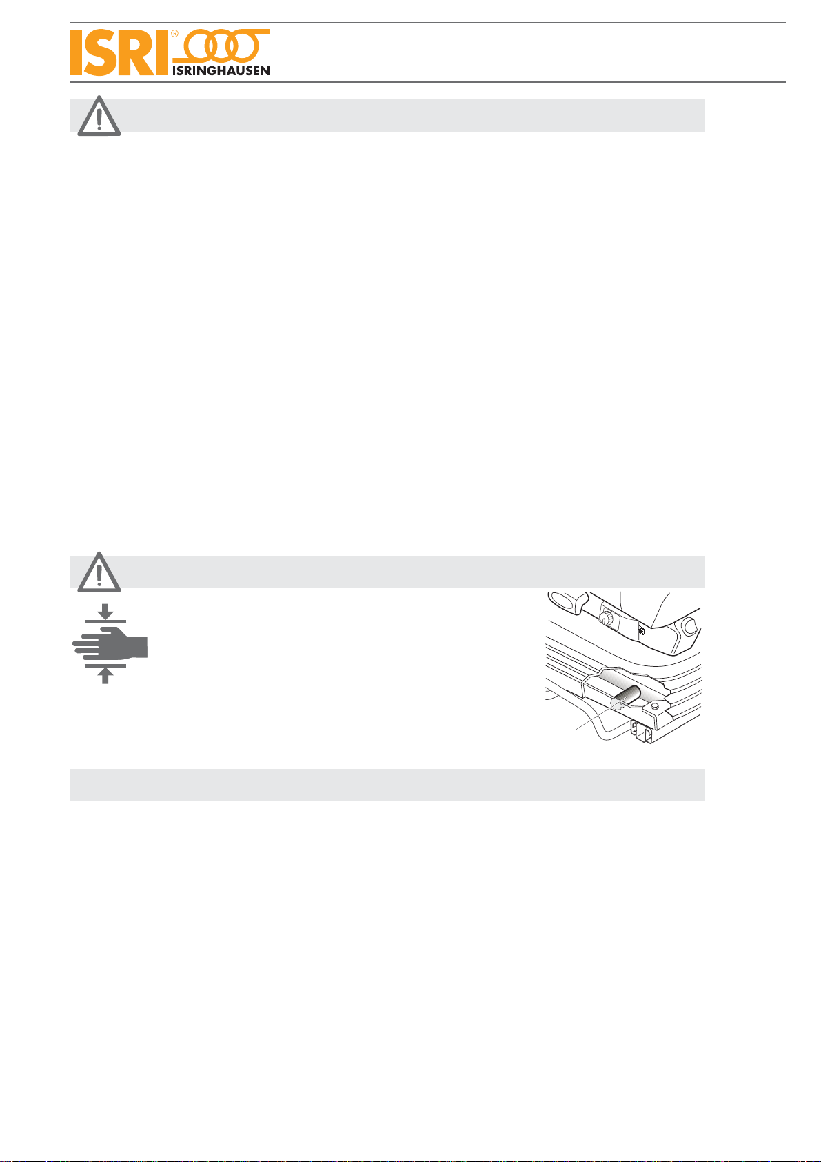
WARNING
CAUTION
For cleaning the seat, use only an slightly dampened cloth without strong solvents.•
The upholstery cover shall not be soaked.•
The seat is suitable for the operator‘s weight of maximum 150 kg.•
• The seat shall not be used as ascent help.•
The seat may not be blocked by objects in the vehicle, otherwise the seat can be damaged.•
Do not place anything on the seat and don`t cover the seat.•
Inappropriate handling of seat heating, respectively wrong connection, can lead to overheating.•
When driving without passenger, take care that the seat heating of the passenger seat are switched• off.
The fuse protection of the seat heating/ active ventilation may be maximally 10A.•
The electrical connection of the seat has to be installed by the vehicle ignition.•
The active ventilation system doesn‘t switch off automatically. The operating happens in self-respon-• sibility of the user.

WARNING NOTES
Hinweise zur Reparaturanleitung:
The illustrations in this manual shows the seat with levers at left side.• For seats with levers at the right side, the repair will be carried out accordingly.
The descriptions in chapter 2 explains the removal of sundry seat components.• The installation of these seat components generally happens in reserve sequence.
Not all fastening parts for hoses and cables (e.g. cable binder) are mentioned in detail.• After repairs it is necessary to put the laying of hoses and cables, as well as the fastening and
securing, into original condition.
Hoses, electrical lines and bowden cables must not be creased.•
Due to safety reasons, pay attention to the correct positioning and to the observance of the tightening• torques of the fixing screws when exchanging component parts, which lies within the flux line of the
belt anchorage points.
All parts of the spare part kit must be exchanged. Don`t use the old mounting parts again.•
After each repair a functional test and, if pneumatic parts are involved, a leak test has to be effected.•
All adjustment mechanism must engage audibly.• Move levers over the complete operation stroke to avoid wear of the mechanism.
Due to reasons of road safety, the seat must only be adjusted when the• vehicle is stationary and the hand brake is pulled.
A wrong adjusted seat risks your driving safety and health.•
Don‘t operate several control elements at the same time.•
Always use the seat belt when driving.•
The shock absorber must be adjusted so tautly, that even when driving a bad road, the contact to the• pedals is ensured.
Don‘t adjust the shock absorber so softly that on rough roads the seat will knock through.•
1
NOTICES
to the repair manual
Due to risk of injury, in several repairs in the inside of the seat,
the seat must be secured against lowering.
Therefor adjust the seat in the topmost position.
Loosen bellows in the lower area and positioning a
distance sleeve (1) with a length of 75mm between lower
frame and scissor.
It will be indicated to this note in the relevant repair
descriptions.
NOTICES for test run
Danger of bruising

1.3.0
SERIAL NUMBER
Serial number
The serial number is located at lever side on the lower frame of the suspension unit and is visible when lifting up the
bellows.
The exact seat type and the seat number can be identified by the serial number.
Please specify for spare part orders always.
Isringhausen
GmbH & Co KG
D - 32657 Lemgo

2.1.0
COMPLETE SEAT/ HORIZONTALADJUSTMENT
Complete seat
Disconnect electrical connection between seat and vehicle.• Pull lever (1) upwards, move seat to the foremost position and undo screws (2).• Pull lever (1) upwards, move seat to the rearmost position and undo screws (3).•
Horizontal adjustment
Dismount seat from vehicle.•
Pull lever (1) upwards and move inner slides till six screws (4) are reachable through boreholes of inner slides.• Undo 6 screws (4).•
Tightening toques
Pos. 4 22Nm +/-2Nm
1
3
4
2

2.2.0
SEAT CUSHION/ SLIDERS FOR SEAT CUSHION
Seat cushion
Lift up lever (1) and push seat cushion in foremost position.• Undo two screws (2).• Hold on lever (1) in upper position and push it sidewards (see arrow A).• Move seat cushion forwards completely and lift it up.• Disconnect electrical feeders.•
Installation seat cushion
Bowden cable (8) must be positioned between lever (9) and seat cushion ground plate.• Push the rear keyholes (4) (on cushion‘s bottom side, view B) onto the rear sliders (7).• Lift up lever (1) (don`t move seat cushion) and push it in direction of arrow Asidewards.• Press down the seat cushion‘s front keyholes (5) onto the sliders at the front and press down cushion in direction• of arrow (F).
Push the cushion in direction of backrest (till stop) while still pressing down the complete seat cushion.• Check now, if all four sliders are locked in the keyholes (no vertival movement allowed).• Push lever (1) in direction of arrow D and push cushion further in direction of backrest, till lever (1) engages.• Take care, that the cushion is locked in horizontal and vertical direction.
Tighten lever for tilt adjustment.•
Sliders for seat cushion (view C)
Demount seat cushion (see 2.2.0).• Pull out plastic pin (6) and take off slider (7).•
Installation sliders
Push slider (7) at the seat frame.• Push in pin (6) ( level of pin head flat must fit to the flat on the slider head).•
4
7
B
6
7
C
4
9
A
D
C
8

1
3
4
2
2
Version with
3-point-belt
5
6
7
2.3.0
BACKREST
Backrest
Demount seat cushion (see 2.2.0).• Demount side covers (see 2.5.0).• Disconnect air hoses of IPS (3).• Disconnect electr. connection (4).• Undo safety clamp (1).• Fold down backrest and unscrew two screws (2).• Lever backrest out of the seat frame brackets.• Possibly remove armrests.•
For version with 3-point-belt:
Unscrew screw (5, long) and screw (6, short) and move belt cover upwards.• Unscrew screw (7) and remove belt deflection.•
Instruction of installation
After mounting, fold down the backrest completely and check IPS hoses for sufficient play.•
Tightening toques
Pos. 2 35Nm +/-5Nm
Pos. 5,6 4Nm
Pos. 7 35Nm +5Nm

2.4.0
COVER SEAT/ BACKREST CHSHION
Cover for seat cushion
Demount seat cushion (see 2.2.0).• Lever seat cushion cover (1) out of groove (2), running around seat ground plate.•
Instruction of installation
Before mounting the cover, rebend hooks in the groove (2) from the ground plate, if necessary.•
Cover for backrest cushion
Disconnect hoses and electrical connector (3).• Unhook C- profiles (4) (see detail A) and (5).• Pull cover upwards and loosen fixing tapes (6).• Remove cardboard (if existing).•
For version with 3-point-belt:
Unscrew screw (7, long) and screw (8, short) and move belt cover upwards.• Unscrew screw (9) and remove belt deflection.•
Instruction of installation
After mounting, fold down the backrest completely and check IPS hoses for sufficient play.
5
3
12
4
6
6
4
A
Version with
3-point-belt
7
8
9
Tightening toques
Pos. 7,8 4Nm
Pos. 9 35Nm +5Nm

4
3
red
2
5
6
white
1
8
10
11
12
13
14
8
7
9
4
V ri nt without
clim tic switch
8
2.5.0
SIDE COVERS/ IPS VALVE/
SWITCH FOR CLIMATIC/ HEATING
Side cover, lever side
Demount seat cushion (see 2.2.0).• Unscrew screw (1), front screw (2)(4,2x25) and back screw (3)(4,2x18).• Undo two pins (4).• Fold down backrest completely and undo one screw (5).• Remove cover (6) from seat frame.•
Side cover, opposite side
Remove cover (14) in general sense of side cover level side.•
IPS valve
Lift up fixing hook (7) and separate air hoses (8) from Y-connector (9).• Disconnect 3 hoses (10) and electr. connection (11).• Press IPS valve out of side cover.•
Switch climatic/ heating
Unhook switch for climatic/ heating (12) from side cover and disconnect electrical connection (13).•
Tightening toques
Pos. 1,2,3,5 2Nm

2.6.0
FRONT COVER/ SWITCH HEIGHTADJUSTMENT/
Front cover/ Rotation switch height adjustment
Push seat cushion in foremost position and lift it up (see 2.2.0).• Undo two screw (1) and lever out front cover (2).• Press out rotation switch for height adjustment from behind of the front cover and disconnect plug (3).•
Rear cover
Undo four pins (4).•
Tightening toques
Pos. 1 2Nm
4
2
1
3
REAR COVER

2.7.0
SWITCH HEIGHTADJUSTMENT
Switch height adjustment
Demount seat cushion (see 2.2.0).• Undo 2 screws (1) and lever out front cover.• Press out switch for height adjustment (3) from behind of the front cover.• Unhinge hoses of switch out of clamp (4)• Loose air hoses (5) (6) (7) at the connectors (9) and (10).• Therefor lift up fixing hook (8) carefully and separate air hoses from connector (9).
8
9
1
1
3
2
4
5
6
710

2.8.0
1
X
2
5
Y
3
4
1
view X
3
7
6
1
LEVER FOR TILTADJUSTMENT
Lever for tilt adjustment
When exchange the lever for tilt adjustment, all parts of the kit must be exchanged!
Demount seat cushion (see 2.2.0).• Demound side cover without disconnecting hoses (see 2.5.0).• Adjust tilt adjustment in upper position.• Press down spring (1), unhook from fixation (2) and pull spring out from levers (3)(4)(5).• Remove lever for horizontal suspension (see 2.10.0).• Lever bearing (7) out of seat frame and remove bowden cable from lever (3).•
• Installation tilt adjustment
When mounting, hook spring (1) at first in lever (4)(5)(3).• Press down spring (1) with a screwdriver in area Y and• hook spring behind fixation (2).
Adjustment of bowden cable
Pull lever for tilt adjustment.• Adjust bowden cable in that way, that between lever (1)• and plate (2) no opening is existing.
The inclination adjustment must release comletely and must move noiselessly when pulling the lever• (no clattering of tooth segments).
1
2
1
2 1 2

2.9.0
SHOCK ABSORBER ADJUSTMENT
Shock absorber adjustment
Demount seat cushion (see 2.2.0).• Remove retaining washer (1) and lever bowden cable (2) out of fastening (3) .• Unscrew two screws (4).• Knock pin (5) out of lever (6) and pull bowden cable out of seat frame.•
12
3
4
5
6
Tightening toques
Pos. 1 5Nm

2.10.0
LEVER FOR HORIZONTAL SUSPENSION
Lever for horizontal suspension
Demount seat cushion (see 2.2.0).• Adjust tilt adjustment in highest position.• Undo two screws (1).• Unhook bowden cable (2) out of lever (3).• Pull out bowden cable from side cover.•
1
2
3
Tightening toques
Pos. 1 5Nm

2.11.0
BACKREST HANDLE
Backrest handle
Remove side cover lever side (see 2.5.0).• Remove retaining washer (1), pull off backrest handle and unhook springs (2) and (3).•
2
3
1

2.12.0
LEVER BACKREST/
SHOULDER ADJUSTMENT
Lever/ lever springs for backrest
Demount side cover for seat frame lever side (2.5.0, without loosen hoses).• Remove safety washer (1).• Demount spring (2) from lever (3) and lever (6).• Pull off lever (3).• Demount spring (5) at Pin (4).•
Lever for shoulder adjustment
Remove safety washer (7) and roller (8).• Cut cable binder (9) and pull out securing plug (10).• Remove cable ball (11) from lever (6) (pull cable out of cable guide, if necessary).• Unscrew screw (12) and pull off lever (6).•
1
2
3
5
6
11 10
9
7
8
12
4
Tightening toques
Pos. 12 16Nm +/-2Nm

2.13.0
TOOTH SEGMENT FOR BACKRESTADJ.
Tooth segment for backrest adjustment
Demount seat cushion (see 2.2.0).• Remove side cover of lever side (see 2.5.0).• Loosen spring (1) at pin (2) of lever (3).• Remove safety clamp (8).• Unscrew nuts (4) and take out plate (5), tooth segment (6) and lever (3).•
Tightening toques
Pos. 4 22Nm +/-2Nm
1
2
3
6
5
8
4
Table of contents
Other ISRI Construction Equipment manuals
Popular Construction Equipment manuals by other brands

Solar Technology International
Solar Technology International PV Logic SKA08 user manual

Viega
Viega MegaPress G Product instructions

Manitowoc
Manitowoc National Crane 600H Operator's manual

Lumag
Lumag EB400PRO Operator's manual

RAIMONDI
RAIMONDI EASY-MOVE MK3 Use and maintenance manual

babcockdavis
babcockdavis GRATEdesign Installation, operation & maintenance manual