ISRINGHAUSEN 6800/338 Bus User manual

Manual No. 7018081-02, Rel. Jun. 1999 © Copyright Isringhausen 1999
Read and understand this manual before servicing this seat.
Isringhausen
Seat Model 6800/338 Bus
Seat Model 6800/338 Premium LX
Service Manual

ii Manual No. 7018081-02, Rel. Jun. 1999© Copyright Isringhausen 1999
INTRODUCTION
SERVICE AND REPAIR
Proper service and repair are important to the safe, reliable operation of this
seat. Service and repair should be preformed only by responsible persons
who have been properly instructed and authorized to do so. The procedures
recommend in this manual are safe effective methods for performing service
and repair operations.
We could not possibly know, evaluate, and advise the service trade of all
conceivable ways in which service can be done or of the possible hazardous
consequences of each way. If you use a service procedure which is not
recommended, be sure that personal safety and equipment safety will not
be jeopardized.
It is the responsibility of the mechanic performing the service and repair to:
• inspect for abnormal wear and damage
• choose a repair procedure that will ensure your safety, the safety of
others, and the safe operation of the equipment
• fully inspect and test the equipment to ensure that the repair or service
has been properly performed and the equipment will function properly.
This manual describes the correct service procedures for Model 6800/348
Premium seats. The information in this manual was current at the time of
printing and is subject to change without notice or liability.
READ AND UNDERSTAND THIS MANUAL AND THE
OPERATOR'S MANUAL
Learn how to service Model 6800/348 Premium seats. Failure to do so could
result in personal injury or equipment damage. Consult your dealer if you do
not understand the instructions in this manual and/or need additional
information.
KEEP THIS MANUAL
This manual should be considered a permanent part of the seat and be
available for reference when servicing the seat.
WARRANTY
Warranty is provided as part of Isringhausen's support program for
customers who operate and maintain their seat as shown in this manual.
See the warranty for details.
MODEL 6800/338 BUS
MODEL 6800/338 PREMIUM LX

1
Manual No. 7018081-02, Rel. Jun. 1999 © Copyright Isringhausen 1999
TABLE of CONTENTS
subject page
INTRODUCTION ii
GENERAL SAFETY 2
TROUBLESHOOTING 3
INSPECTION 4
REMOVALAND INSTALLATION
ARMREST 6
BACKREST 6
BACKRESTASSEMBLY 7
LUMBAR/BOLSTER AIR BAGS 7
LUMBAR/BOLSTER VALVE 8
COVER FRONT, LH AND RH 8
SEAT PAN ASSEMBLY 9
GLIDE - SEAT PAN 9
SEAT PAN ASSEMBLY LEVER
AND HANDLE 10
HEIGHTADJUSTMENT VALVE -
SUSPENSION 10
subject page
HEIGHTADJUSTMENT HANDLE 11
HEIGHTADJUSTMENT CYLINDER AND CAM 11
HORIZONTALADJUSTMENT SLIDE SET 12
QUICK AIR RELEASE VALVE AND HANDLE 12
QUICK AIR RELEASE VALVE - SUSPENSION 13
RISER AND SUSPENSION 13
SEAT FRAME 14
SEAT FRAME TOOTH PLATE 14
BACKRESTADJUSTMENT HANDLE 15
TILT ADJUSTMENT HANDLE 15
AIR SPRING 16
BOOT, BOOTADAPTER PLATE,
ICP BAR, AND TETHERS 16
ADJUSTABLE SHOCK ABSORBER CABLE 17
ADJUSTABLE SHOCK ABSORBER 17
DISTRIBUTION VALVE 18
HEADREST 18
PARTS 19
REMOVALAND INSTALLATION PAGE NUMBERS
MODEL 6800/338 BUS
MODEL 6800/338 PREMIUM LX

2Manual No. 7018081-02, Rel. Jun. 1999© Copyright Isringhausen 1999
GENERAL SAFETY
In this manual safety messages will alert persons to a specific hazard, the
degree or level of hazard seriousness, the probable consequences of
involvement with the hazard, and how the hazard can be avoided. Safety
messages will include the safety alert symbol, a signal word, and a word
message.
SAFETY ALERT SYMBOL
Indicates a potential personal safety hazard.
SIGNAL WORDS
DANGER: Indicates an imminently hazardous situation which, if not
avoided, will result in death or serious injury.
WARNING: Indicates an potentially hazardous situation which, if not
avoided, could result in death or serious injury.
CAUTION: Indicates an potentially hazardous situation which, if not
avoided, may result in minor or serious injury.
WORD MESSAGE
The word message will identify the hazard, indicate how to avoid the
hazard, and advise of probable consequence of not avoiding the hazard.
MODEL 6800/338 BUS
MODEL 6800/338 PREMIUM LX

3
Manual No. 7018081-02, Rel. Jun. 1999 © Copyright Isringhausen 1999
TROUBLESHOOTING
MODEL 6800/338 BUS
MODEL 6800/338 PREMIUM LX
Problem Cause Solution Page
Armrest will not stay in position. Armrest control is defective. Replace armrest. 6
Backrest will not adjust Teeth on backrest are defective. Replace backrest. 6
and/or stay adjusted. Backrest seat latch is defective. Replace backrest seat latch. 14
Lumbar/Bolster No air supply to seat. 90 to 145 psi req'd. 5
will not inflate. Air lines leak. Replace air lines. 7
Valve is defective. Replace valve. 8
Air bags leak. Replace air bags. 7
Height will not adjust and/or Height adj. cam is defective. Replace height adj. cam. 11
stay adjusted. Height adj. cylinder is defective. Replace height adj. cylinder. 11
Height adj. valve is defective. Replace height adj. valve. 10
Horizontal slide will not adjust Horizontal slide is defective. Replace horizontal slide. 12
and/or stay adjusted.
Seat pan assem. will not adjust Seat pan lever is defective. Replace seat pan lever. 10
and/or stay adjusted. Seat pan glides are defective. Replace seat pan glides. 9
Quick air release No air supply to seat. 90 to 145 psi req'd. 5
will not function. Valve is defective. Replace valve. 12
Adjustable shock absorber Shock absorber is defective. Replace shock absorber. 17
will not adjust. Shock absorber cable is defective. Replace shock absorber cable. 17
Suspension will not Suspension is defective. Replace suspension. 13
function properly.

CAUTION
Avoid the risk of injury.
Vehicle must be in a safe parked
position before inspecting seat.
Visually inspect the seat. Look for damaged or worn upholstery and parts. The seat should be clean and free
of dirt and debris. Check all the seat functions they should work properly and be in good condition.
1. Adjustable armrest
Should move up freely, the adjustment knob should be easy to turn and
the armrest must stay in the adjusted position.
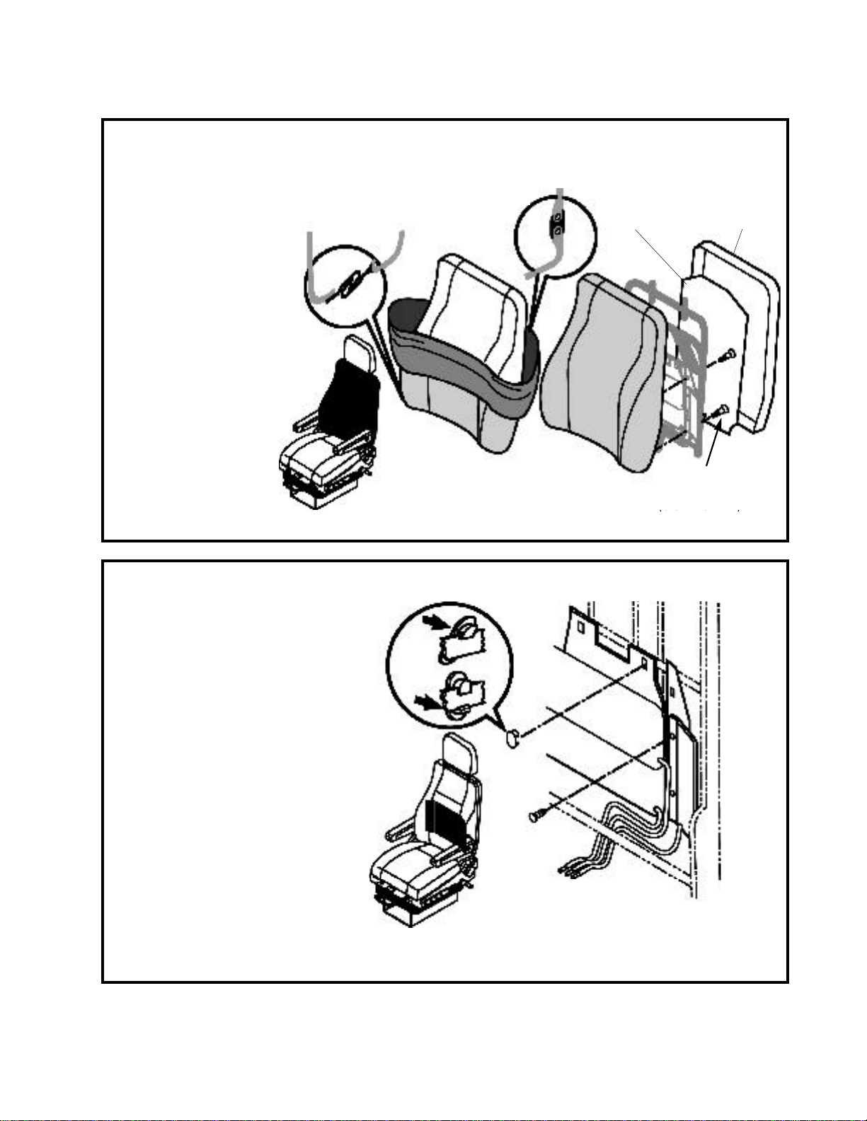
2. Backrest adjustment
The control should be easy to release then the backrest should
move freely. The backrest must stay in the adjusted position.
3. Backrest side bolster
The control should be easy to move to the inflate or deflate
position and must return to neutral when released. Each side
support should inflate and deflate evenly and stay at the
adjusted firmness..
4. Height adjustment
Control should be easy to move and hold the seat in the
adjusted position when released.
5. Horizontal adjustment
Control should be easy to move and hold the seat in the
adjusted position when released.
6. Seat tilt adjustment
Control should be easy to move and hold the seat in
position when released.
7. Lower and upper lumbar support
The controls should be easy to move to the inflate or
deflate position and must return to neutral when
released. Each lumbar support must stay at the
adjusted firmness.
8. Cushion length adjustment
Control should be easy to move and hold the seat
cushion in the adjusted position when released.
9. Adjustable shock absorber
Control should be easy to move and stay in position when
released.
10. Quick air release
Control should be easy to move and hold seat in the adjusted position when released.
11. Horizontal isolator
Control should be easy to move and stay in position when released.
12. Headrest
Should be easy to move up and down and stay in position. Headrest should tilt forward and backward freely.
If the seat is not functioning properly take it out of service until it can be repaired.
4Manual No. 7018081-02, Rel. Jun. 1999
INSPECTION
© Copyright Isringhausen 1999
MODEL 6800/338 BUS
MODEL 6800/338 PREMIUM LX
1
2
9
10
11
8
64
7
5
3
3
12
2

5
Manual No. 7018081-02, Rel. Jun. 1999 © Copyright Isringhausen 1999
INSPECTION
MODEL 6800/338 BUS
MODEL 6800/338 PREMIUM LX
Air supply
Critical fastener torque
Air supply to seat must 90 to 145 p.s.i.
Suspension to riser
torque to
14.8 - 18.4 lb ft (20 - 25 N•m))
Seat rails to suspension
torque to
14.8 - 18.4 lb ft (20 - 25 N•m)
Seat to seat rails
torque to
14.8 - 18.4 lb ft (20 - 25 N•m)
Armrest to seat
torque to
14.8 - 18.4 lb ft
(20- 25 N•m)

6Manual No. 7018081-02, Rel. Jun. 1999
REMOVAL andINSTALLATION
© Copyright Isringhausen 1999
MODEL 6800/338 BUS
MODEL 6800/338 PREMIUM LX
Armrest
Set up
• Vehicle must be in a safe parked
position or seat removed from
vehicle.
Removal
• Remove fasteners
• Remove armrest
Installation
• Fasten armrest to seat with screws
and lockwashers.
• Torque screws to 14.8 - 18.4 lb ft (20
- 25 N•m)
Backrest
Set up
• Vehicle must be in a safe parked
position or seat removed from
vehicle.
Removal
• Mark and disconnect air lines
• Remove fasteners
• Pry one side of seat frame away from
backrest
• Remove backrest
Installation
• Put one side of backrest in place
• Pry other side of seat frame away
and put backrest in place
• Fasten backrest to seat frame with
shoulder bolts
• Torque shoulder bolts to 22 - 25.5 lb
ft (30 - 35 N•m)
• Connect air lines
CAUTION
Avoid the risk of injury. Vehicle must be in a safe parked position before working on the seat.
NOTICE
To remove seat from vehicle follow vehicle manufacturer's instructions.

7
Manual No. 7018081-02, Rel. Jun. 1999 © Copyright Isringhausen 1999
REMOVAL andINSTALLATION
MODEL 6800/338 BUS
MODEL 6800/338 PREMIUM LX
Lumbar and bolster
air bags
Set up
• Remove backrest components (see
Backrest assembly)
Removal
• Remove air bag clips, push fasteners
and cable ties
• Remove air bags
Installation
• Fasten air bags to backrest frame
with clips - put long clip arm over bar
and snap bottom of clip in place
• Install push fasteners and cable ties
Backrest assembly
Set up
• Backrest must be removed
from seat (see Backrest)
Removal
• Premium XL - remove
upholstery and backrest
liner
• Bus - remove cover, hog
rings and wires.-- remove
upholstery
• Remove backrest cushion
fasteners -- remove cushion
Installation
• Fasten backrest cushion to
backrest frame with screws
• Premium XL - install
backrest liner and
upholstery
• Bus - install upholstery,
hog rings and wires.-- install
cover
torque to
5.3 - 8.8 lb in
(0.6 - 1.0 N•m)
do not over tighten
Premium XL Premium XL
Bus
Bus

8Manual No. 7018081-02, Rel. Jun. 1999
REMOVAL andINSTALLATION
© Copyright Isringhausen 1999
MODEL 6800/338 BUS
MODEL 6800/338 PREMIUM LX
Lumbar and bolster valve
Set up
• Cover must be removed from seat
(see Covers front, LH and RH)
Removal
• Mark air line and remove them from
valve
• Press valve clips in and remove
valve from cover
Installation
• Snap valve into cover
• Connect air lines
Covers, LH and RH
Set up
• Vehicle must be in a safe parked position or
seat removed from vehicle.
Removal
Control cover
• Remove backrest adjustment handle
• Remove tilt adjustment handle - for fastener
access
• Remove fasteners and cover
Non control cover
• Remove fasteners and cover
Installation
Control cover
• Fasten cover to seat frame with screws
• Install backrest adjustment handle
• Install tilt adjustment handle - removed for
fastener access
Non control cover
• Fasten cover to seat frame with screws
torque to
5.3 - 8.8 lb in
(0.6 - 1.0 N•m)
do not over tighten

9
Manual No. 7018081-02, Rel. Jun. 1999 © Copyright Isringhausen 1999
REMOVAL andINSTALLATION
MODEL 6800/338 BUS
MODEL 6800/338 PREMIUM LX
Seat pan assembly
Set up
• Vehicle must be in a safe
parked position or seat
removed from vehicle.
Removal
• Slide cushion assembly
forward
• Pry lever handle up to
release cushion stop -- lift
cushion off of glides
Installation
• Put seat cushion assembly
on glides and slide back
Glides - seat pan
Set up
• Seat cushion must be removed from
seat (see Cushion seat pan)
Removal
• Remove cushion glides
Installation
• Install cushion glides to seat frame

10 Manual No. 7018081-02, Rel. Jun. 1999
REMOVAL andINSTALLATION
© Copyright Isringhausen 1999
MODEL 6800/338 BUS
MODEL 6800/338 PREMIUM LX
Seat pan assembly, lever
and handle
Set up
• Seat cushion must be removed from
seat (see Cushion seat pan)
Removal
• Pull handle off
• Remove lever fasteners and remove
lever
Installation
•Align locator button of lever with hole
in seat pan
• Fasten lever to seat pan with screw
and washer
• Push handle on
torque to
7.4 - 8.1 lb ft
(10-11 N•m)
Height adjustment valve
Set up
• Seat cushion must be removed from
seat (see Cushion seat pan)
Removal
• Mark and remove air lines from valve
• Remove valve fasteners
* Remove valve
Installation
• Fasten valve to seat frame with
screw
• Connect air lines
torque to
15.9-19.5 lb in
(1.8-2.2 N•m)
do not over tighten

11
Manual No. 7018081-02, Rel. Jun. 1999 © Copyright Isringhausen 1999
REMOVAL andINSTALLATION
MODEL 6800/338 BUS
MODEL 6800/338 PREMIUM LX
Height adjustment handle
Set up
• Vehicle must be in a safe parked
position or seat removed from vehicle
• Control cover must be removed (see
Covers front, LH and RH)
Removal
• Remove screw and cam
• Pull handle and lever out
• Remove retainers
Installation
• Put upper retainers in place
• Put lever in place
• Put lower retainers in place - be sure
it snaps in place
• Install cam and screw
• Install handle
Height adjustment cylinder
and cam
Set up
• Vehicle must be in a safe
parked position or seat removed from
vehicle
• Seat cushion must be removed from
seat (see Cushion seat pan)
Removal
Air cylinder
• Remove base end pin and retainer
washer - remove rod end fastener,
air line, and remove cylinder
Cam
• Remove rod end fastener
• Remove E ring and mounting pin
• Remove cam
Installation
Air cylinder
• Put cylinder in place and install base
end pin and retainer washer - install
rod end fastener, connect air line
Cam
• Put cam in place and install pin and
E ring 1 = Cylinder kit
2 = Cam kit
1
2
2
2
1
1&2

12 Manual No. 7018081-02, Rel. Jun. 1999
REMOVAL andINSTALLATION
© Copyright Isringhausen 1999
MODEL 6800/338 BUS
MODEL 6800/338 PREMIUM LX
Horizontal adjustment
slide set
Set up
• Seat frame must be removed
(see Seat frame)
Removal
• Move horizontal adjustment
forward or back to allow
access to fasteners
• Remove mounting fasteners
Installation
• Move horizontal adjustment
forward or back to allow
access to fasteners
• Install mounting fasteners
torque to
14.8 - 18.4 lb ft
(20 - 25 N•m)
Quick air release - valve
and handle LH and RH
Set up
• Seat cushion must be removed
from seat (see Cushion seat
pan)
Removal
• Mark and remove air lines from
valve
• Remove valve fasteners
• Remove valve
• Remove valve handle pin and
valve handle
Installation
• Fasten valve handle to valve
with pin
• Fasten valve to seat frame with
screw
• Connect air lines torque to
15.9 - 19.5 lb in
(1.8 - 2.2 N•m)

Riser and Suspension
Set up - riser and suspension
• Vehicle must be in a safe parked
position or seat removed from vehicle.
Set up - suspension
• Boot, Boot adapter plate, ICP bar, and
tethers must be removed (see Boot,
Boot adapter plate, ICP bar, and
tethers)
Removal - suspension
• Remove air line
• Remove suspension to riser fasteners
and remove suspension
Installation - suspension
• Put suspension in place
• Install fasteners and torque to 14.8 -
18.4 lb ft (20 - 25 N•m)
• Connect air line
Removal - riser
• Remove riser to floor fasteners and
remove riser
Installation - riser
• Put riser in place and install fasteners,
torque to manufactures specification
13
Manual No. 7018081-02, Rel. Jun. 1999 © Copyright Isringhausen 1999
REMOVAL andINSTALLATION
MODEL 6800/338 BUS
MODEL 6800/338 PREMIUM LX
Quick air release valve -
suspension
Set up
• Seat cushion must be removed
from seat (see Cushion seat
pan)
Removal
• Mark and remove air lines from
valve
• Remove valve fasteners and
remove valve
Installation
• Fasten valve to suspension with
screws
• Connect air lines
torque to
15.9 - 19.5 lb in
(1.8 - 2.2 N•m)
torque to
manufactures
recommendation

14 Manual No. 7018081-02, Rel. Jun. 1999
REMOVAL andINSTALLATION
© Copyright Isringhausen 1999
MODEL 6800/338 BUS
MODEL 6800/338 PREMIUM LX
Seat frame
Set up
• Seat cushion and backrest must
be removed from seat (see
Cushion seat pan and
Backrest)
• Shock absorber handle and
cable must be removed. (see
Adjustable shock absorber
handle and cable - handle
end)
Removal
• Mark and remove air lines
• Remove fasteners
• Remove seat frame
Installation
• Fasten seat frame to static
spacer rails with bolts and nuts
• Torque fasteners to 14.8 - 18.4
lb ft (20 - 25 N•m)
• Connect air lines
Seat frame tooth plate
Set up
• Backrest and covers must be
removed from seat (see
Backrest and Covers front, LH
and RH)
Removal
• Remove seat latch fasteners
• Remove seat latch
• Remove connecting link
Installation
• Install connecting link
• Fasten seat latch to seat frame
with screws
torque to
14.8 - 18.4 lb ft
(20 - 25 N•m)

15
Manual No. 7018081-02, Rel. Jun. 1999 © Copyright Isringhausen 1999
REMOVAL andINSTALLATION
MODEL 6800/338 BUS
MODEL 6800/338 PREMIUM LX
Backrest adjustment handle
Set up
• Vehicle must be in a safe parked position
or seat removed from vehicle.
Removal
• Pull handle off
Installation
• Push handle on
Tilt handle
Set up
• Vehicle must be in a safe parked
position or seat removed from vehicle.
Removal
• Remove springs
• Pull handle and lever out
• Remove retainer
Installation
• Put lever in place
• Install retainer, be sure it snaps in place
• Install springs
• Install handle

16 Manual No. 7018081-02, Rel. Jun. 1999
REMOVAL andINSTALLATION
© Copyright Isringhausen 1999
MODEL 6800/338 BUS
MODEL 6800/338 PREMIUM LX
Air spring
Set up
• Seat must be removed from
vehicle
• Seat cushion must be removed
from seat (see Cushion seat
pan)
Removal
• Mark and disconnect air line
• Remove top and bottom
mounting fasteners
• Remove air spring
Installation
• Put air spring in place
• Install top and bottom mounting
fasteners
• Connect air line
torque to
44.2 - 62 lb in
(5 - 7 N•m)
do not over tighten
Boot, Boot adapter plate,
ICP bar, and tethers
Set up
• Vehicle must be in a safe parked
position or seat removed from vehicle
• Horizontal adjustment must be
removed (see Horizontal
adjustment)
Removal
• Remove belts from ICP bar
• Remove boot fasteners, remove
boot, and boot adapter plate
• Remove fasteners, tether plate,
tether brackets, tethers, and ICP
bar
Installation
• Install fasteners, tether plate,
tether brackets, tethers, and
ICP bar
• Install boot adapter plate, boot, and
fasteners
• Install belts to ICP bar
torque to
14.8 - 18.4 lb ft
(20 - 25 N•m)

17
Manual No. 7018081-02, Rel. Jun. 1999 © Copyright Isringhausen 1999
REMOVAL andINSTALLATION
MODEL 6800/338 BUS
MODEL 6800/338 PREMIUM LX
Adjustable shock absorber
handle and cable
(handle end)
Set up
• Seat cushion must be removed from
seat (see Cushion seat pan)
Removal
• Remove fasteners and move
control, bracket, and cable
up away from seat frame
• Remove control handle pin
and control handle
• Remove cable pin and cable
• Remove plug from bracket and
remove cable
Installation
• Put cable in bracket and secure with
plug
• Route cable through control body
and fasten to control handle with pin
• Fasten control handle to control body
with pin
• Fasten control and bracket to frame
with screws
Adjustable shock absorber and
cable (shock absorber end)
Set up
• Vehicle must be in a safe parked position or
seat removed from vehicle
• Seat cushion must be removed
from seat (see Cushion seat pan)
Removal
Adjustable shock absorber
• Remove retaining rings
• Remove shock absorber
Adjustable shock absorber cable
• Remove retaining ring
• Remove cable
Installation
Adjustable shock absorber cable
• Put cable in place
• Install retaining ring
Adjustable shock absorber
• Put shock absorber in place
• Install retaining rings

18 Manual No. 7018081-02, Rel. Jun. 1999
REMOVAL andINSTALLATION
© Copyright Isringhausen 1999
MODEL 6800/338 BUS
MODEL 6800/338 PREMIUM LX
Distribution valve
Set up
• Seat cushion must be removed
from seat (see Cushion seat
pan)
Removal
• Mark and remove air lines from
valve
• Remove valve fastener and
remove valve
Installation
• Fasten valve to frame with screw
• Connect air lines
Headrest
Set up
• Vehicle must be in a safe parked
position or seat removed from
vehicle
Removal
• Pull headrest to upper locking
position
• Press foam, as shown, to
release locking clip from detent
on headrest and pull up
Installation
• Guide headrest bars into position
• Press down to engage locking
clip
PRESS
HERE
This manual suits for next models
1
Table of contents
Popular Automobile Accessories manuals by other brands

Mountain Top
Mountain Top Wildtrak troubleshooting manual

Mid America Motorworks
Mid America Motorworks 658-129 instruction sheet

Buyers Products Company
Buyers Products Company KabGard 85104 installation instructions

Volvo
Volvo 30721673 Installation instructions, accessories

Smappee
Smappee EV Base installation manual

Car-Interface
Car-Interface CI-AUX-110 manual