18 CHANNELS LED DRIVER EVALUATION BOARD GUIDE
Integrated Silicon Solution, Inc. – www.issi.com 2
Rev. A, 04/03/2018
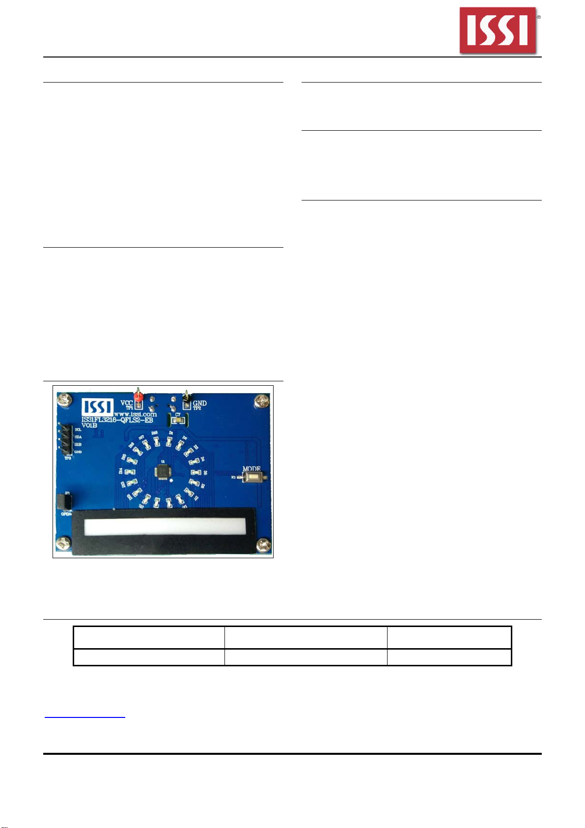
EVALUATION BOARD OPERATION
The evaluation board is controlled by LPC922.
IS31FL3218 evaluation board has 8 modes:
1) Mode1: 3 single color LEDs chase after other 3
single color LEDs
2) Mode2: 9 single color LEDs chase after other 9
single color LEDs
3) Mode3: single colors LEDs go round and round,
the speed is slow and then hurries up.
4) Mode4: 3 groups single color LEDs on two sides
circumrotated.
5) Mode5: 18 single color LEDs breathe.
6) Mode6: the color of RGB LEDs are changing and
moving from RGB1 to RGB6 all the time.
7) Mode7: the RGB LEDs (RGB1-RGB6) are
breathing, and the color is changing all the time
8) Mode8: the RGB LEDs (RGB1-RGB6) are
changing color from two sides to middle.
Note: IS31FL3218 solely controls the FxLED function on the
evaluation board.
SOFTWARE SUPPORT
JP1 default setting is closed (jumper on). If it is open
(when the EVB is powered on by 5V DC or
micro-USB, no jumper JP1), the on-board MCU will
configure its own I2C/SDB/AD pins to High
Impedance status so an external source can driver
the I2C/SDB signals to control the IS31FL3218 LED
driver, the on-board MCU will also configure the U4 to
open the VLED (Single color LED+) and close the
VRGB.
GND
SDA SCL
SDB VCC
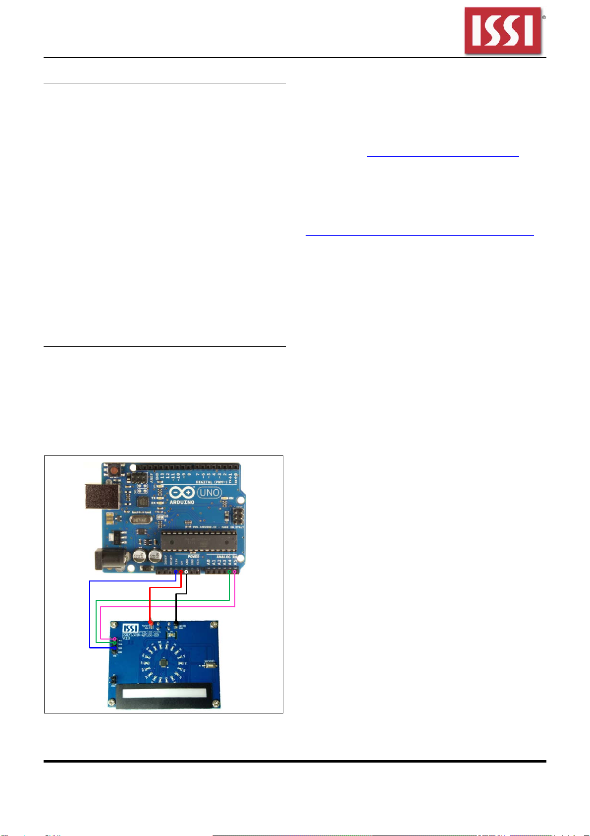
Figure 2: Photo of Arduino UNO connected to Evaluation
Board
The steps listed below are an example using the
Arduino for external control.
The Arduino hardware consists of an Atmel
microcontroller with a bootloader allowing quick
firmware updates. First download the latest Arduino
Integrated Development Environment IDE (1.6.12 or
greater) from www.arduino.cc/en/Main/Software. Also
download the Wire.h library from
www.arduino.cc/en/reference/wire and verify that
pgmspace.h is in the directory …program
Files(x86)/Arduino/hardware/tools/avr/avr/include/avr
/. Then download the latest IS31FL3218 test firmware
(sketch) from the ISSI website
http://www.issi.com/US/product-analog-fxled-driver.shtml.
1) Keep the JP1 shorted.
2) Power on the Arduino UNO.
3) Connect the 2 pins from Arduino board to
IS31FL3218 EVB:
a) Arduino GND to IS31FL3218 EVB GND
(TP1).
b) Arduino 5V pin to IS31FL3218 EVB VCC
(TP2).
The on-board MCU will start to run in default
mode (Mode1).
4) Open the JP1, the on-board configure the
SDA/SCL/SDB to Hi-Z status, all LEDs are turned
off.
5) Connect the 3 pins from Arduino board to
IS31FL3218 EVB:
a) Arduino SDA (A4) to IS31FL3218 EVB SDA
(TP3).
b) Arduino SCL (A5) to IS31FL3218 EVB SCL
(TP3).
c) If Arduino use 3.3V MCU VCC, connect
3.3V to IS31FL3218 EVB SDB, if Arduino
use 5.0V MCU VCC, connect 5.0V to EVB
SDB (TP3).
(Arduino UNO is 5.0V, so SDB=5.0V)
6) Use the test code in appendix I or download the
test firmware (sketch) from the ISSI website,
a .txt file and copy the code to Arduino IDE,
compile and upload to Arduino.
7) Run the Arduino code and the single LED will run
the Arduino code. If need to swap to RGB display,
one way is de-soldering the U4 and short the
U4’s pin 3 and pin 5 or pin 6 to enable the power
of RGB.
Please refer to the datasheet to get more information about
IS31FL3218.