ISSI IS32LT3120 User manual

IS32LT3120 Dual Channel Linear LED Driver With Fade In/Fade Out
Integrated Silicon Solution, Inc. – www.issi.com 1
Rev.A, 08/11/2014
DESCRIPTION
The IS32LT3120 is a linear programmable current
regulator consisting of 2 output channels capable of up
to 200mA each. Each channel features an ON/OFF
input pin to toggle the channel between the OFF
condition and the source condition.
The device integrates 63 steps fade in and fade out
algorithm (Gamma correction) which causes the output
LED current to gradually ramp up to the full source
value after the channel’s control pin is pulsed. The
same controller causes the LED current to gradually
ramp down to zero if the channel’s input control pin is
pulsed while the output channel is on.
FEATURES
Dual output channels source up to 200mA each
Independent debounced ON/OFF control for each
channel
Programmable current via a single external
resistor
Programmable fade in, fade out via external
resistor
- Pull down resistor value sets fade speed
- Gamma corrected fade in/out algorithm
Fault Protection:
- LED string shorted to GND
- Over temperature
SOP-8-EP packages
Automotive Grade - AEC-Q100 (pending)
Operating temperature range from -40°C ~ +125°C
QUICK START
Figure 1: Photo of IS32LT3120 Evaluation Board
RECOMMENDED EQUIPMENT
12V,1A DC power supply
ABSOLUTE MAXIMUM RATINGS
≤45V power supply
Caution: Do not exceed the conditions listed above, otherwise
the board will be damaged.
PROCEDURE
The IS32LT3120 evaluation board is fully assembled
and tested. Follow the steps listed below to verify
board operation.
Caution: Do not turn on the power supply until all connections
are completed.
1) Connect the ground terminal of the power supply
to the GND and the positive terminal to the VCC.
NOTE: The VCC supply should be set close to the
IS32LT3120 minimal headroom voltage of 0.5V
(Vcc – Voutx) for best thermal performance. The
board can be operated with a larger headroom
voltage as long as the increase in package
temperature is monitored. Exceeding the device
package temperature specification will cause the
device to enter thermal protection mode.
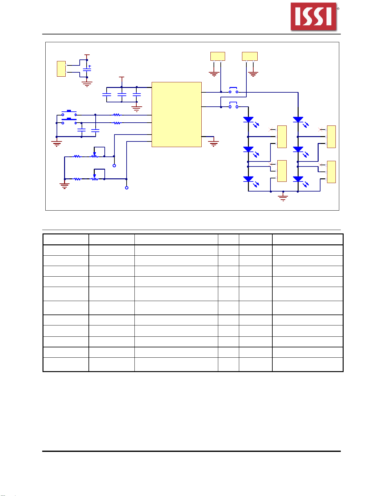
2) The fade time of both channels is adjusted by the
variable resistor (RW1).Turn RW1 counter
clockwise to decrease fade time, and clockwise to
increase fade time. Once the desired fade time is
set, measure the resistor value across TP1 and
GND. Use this measured resistor value to replace
the variable resistor RW1 and R3 (see schematic
Figure 2).
3) The output current of both channels (OUT1 and
OUT2) is adjusted by the variable resistor (RW2).
Turn RW2 counter clockwise to decrease the
output current of both channels, and clockwise to
increase the output current of both channels. The
test point TP2 can be used to detect the resistor
value at the ISET pin. The final resistance can be
measured with an ohm meter across TP2 and
GND pins. Use this measured resistor value to
replace the variable resistor RW2 and R4 (see
schematic Figure 2).
4) Momentary contact buttons (K1, K2) are used to
individually enable/disable the Outx LED channels.
Press K1 to enable the onboard LED string for
channel 1. Press K2 to enable the onboard LED
string for channel 2. In both cases wait for the
LED string to be fully ON (fade time completed)
before pressing the button (K1 or K2) to turn OFF
the corresponding LED string. Always wait for
completion of fade time before pressing either K1
or K2.
5) JP1is used to connect the IS32LT3120 Out 1 (pin
4) to the onboard LED string (LED1, LED3 and
LED5). JP2 connects the device Out2 (pin 5) to
the onboard LED string (LED2, LED4, LED6). Use
one of the green terminal blocks to connect an
external LED string. Remove the corresponding
jumper header (JP1 or JP2) to disable the
onboard LED string. Note: Connecting an
external LED string without removing the onboard
string jumper header will drive both onboard and
external LED strings in parallel resulting in lower
current drive to both strings.

IS32LT3120 Dual Channel Linear LED Driver With Fade In/Fade Out
Integrated Silicon Solution, Inc. – www.issi.com 2
Rev.A, 08/11/2014
6) The on board LED string size can be adjusted
from 1 to 3 LEDs by using jumper headers
JP3~JP6. Connecting the header to pins 2-3
disables the corresponding LED, ie JP3 pins 2-3
disables LED3. To enable all the LED3~LED6
connect JP3~JP6 to pins 1-2.
.
ORDERING INFORMATION
Part No. Temperature Range Package
IS32LT3120-GRLA3-EB -40°C ~ +125°C (Automotive) SOP-8-EP, Lead-free
Table1: Ordering Information
For pricing, delivery, and ordering information, please contact ISSI’s analog marketing team at
EVALUATION BOARD OPERATION
IS32LT3120 evaluation board drives two strings of
WLEDs. There are two variable resistors used for
adjusting the fade time (RW1), LED current (RW2).
SETTING THE FADE TIME
The fade time, either in or out, for both channels is the
same, and is set by a single external programming
resistor (RTSET). The fade time is programmable by
Equation (1):
sRt TSET
5.2 (1)
For example, RTSET=100kΩ, fade time is about 0.25s.
Note: In order to get the optimized effect, the recommended
fading time is between 1.5s (RTSET=600kΩ) and 0.25s
(RTSET=100kΩ).
If the TSET pin is tied directly to GND, the fade in/out
function is canceled and the ramp time is about 73µs,
or ‘instant on’. However, the debounce feature of the
ENx pin is not disabled.
OUTPUT CURRENT SETTING
A single programming resistor (RISET) controls the
maximum output current for both output channels
simultaneously. The programming resistor may be
computed using the following Equation:
SET
ISET I
R2000
(10kΩ≤RISET≤100kΩ)
The device is protected from an output over current
condition caused by an accidental short circuit of the
ISET pin, by internally limiting the maximum current in
the event of an ISET short circuit to 260mA.
THERMAL ROLLOFF
The output current of both channels will be equal to the
set value so long as the die temperature of the IC
remains below 125°C (Typical). If the die temperature
exceeds this threshold, the output current of the device
will begin to reduce at a rate of 3%/°C.
The roll off slope is related to ISET value. When
ISET=20mA, the roll off slope is about 3.7%. When
ISET=200mA, the roll off slope is about 2.2%
FAULT DETECTION
An output shorted to GND fault is detected if the output
voltage on a channel drops below the low voltage
threshold VSCD and remains below the threshold for tFD.
The channel (OUTx) with the short condition will
reduce its output current to 20% of ISET.
When short condition is removed, output current will
recover to original value.
When output current is larger than limit value, about
260mA, the output current will be clamped. When the
open fault condition is recovered, there will be a large
current pulse about 10µs.

IS32LT3120 Dual Channel Linear LED Driver With Fade In/Fade Out
Integrated Silicon Solution, Inc. – www.issi.com 3
Rev. A,08/11/2014
VCC
6
EN1
8
EN2
7
TSET
1GND 3
OUT1 4
OUT2 5
ISET
2
U1
IS32LT3120
C3
1uF
C4
1uF
C6
47uF/63V
C5
0.1uF
R1 0R
R2 0R
K1
K2 C2
NC
C1
NC
0~500K
RW1
0~100K
RW2
R3
100K
R4
10K
OUT1 JP1
OUT2 JP2
LED1
LED3
LED5
LED2
LED4
LED6
3
2
1
JP3
3
2
1
JP5
3
2
1
JP4
3
2
1
JP6
VCC
2
1
OUT1 Terminal
2
1
OUT2 Terminal
2
1GND
VCC
VCC
TP1
TP2
Figure 2: IS32LT3120 Application Schematic
BILL OF MATERIALS
Name Symbol Description Qty Supplier Part No.
LED Driver U1 LED Driver 1 ISSI IS32LT3120
Resistor R3 RES,100k,1/8W,±1%,SMD 1 YAGEO RC1206FR-07100KL
Resistor R4 RES,10k,1/8W,±1%,SMD 1 YAGEO RC1206FR-0710KL
Resistors R1,R2 RES,0ohm,1/16W,±5%,SMD 2 YAGEO RL0603JR-0700RL
Variable
Resistor RW1, RES,0~500K 1
Variable
Resistor RW2 RES,0~100K 1
Capacitor C6 CAP,47µF,63V,±20%,SMD 1
Capacitor C5 CAP,0.1µF,50V,±10%,SMD 1 YAGEO CC0603JKX7R9BB104
Capacitor C3,C4 CAP, 1µF,50V,±10%,SMD 2 YAGEO CC0805JKX7R9BB105
Button K1,K2 Momentary Button SMD 2
Term in al
blocks OUT1,OUT2 green terminal blocks 2
Bill of materials, refer to Figure 2 above.

IS32LT3120 Dual Channel Linear LED Driver With Fade In/Fade Out
Integrated Silicon Solution, Inc. – www.issi.com 4
Rev. A,08/11/2014
0
1
2
3
4
5
6
7
8
910
0
1
2
3
4
5
6
7
8
910
0
1
2
3
4
5
6
7
8
910
0
1
2
3
4
5
6
7
8
910
0
1
2
3
4
5
6
7
8
910
0
1
2
3
4
5
6
7
8
910
1
1
1
1
1
1
1
1
00
0 0
00
0
0
0
0
3
2
1
3
2
1
3
2
1
3
2
1
2
1
2
1
0
0
0
0
0
0
0 1 2
3 3
4
4
0 1 2
3 3
4
4
1
2
2 1 2 1
Figure 3: Board Component Placement Guide -Top Layer
Figure 4: Board Component Placement Guide -Top Layer

IS32LT3120 Dual Channel Linear LED Driver With Fade In/Fade Out
Integrated Silicon Solution, Inc. – www.issi.com 5
Rev. A,08/11/2014
0
1
2
3
4
5
6
7
8
910
0
1
2
3
4
5
6
7
8
910
0
1
2
3
4
5
6
7
8
910
0
1
2
3
4
5
6
7
8
910
0
1
2
3
4
5
6
7
8
910
0
1
2
3
4
5
6
7
8
910
1
1
1
1
1
1
1
1
00
0 0
00
0
0
0
0
3
2
1
3
2
1
3
2
1
3
2
1
2
1
2
1
0
0
0
0
0
0
012
3 3
4
4
0 1 2
3 3
4
4
1
2
2 1 2 1
Figure 5: Board PCB Layout- Top Layer
Figure 6: Board PCB Layout- Top Layer
Copyright © 2014 Integrated Silicon Solution, Inc. All rights reserved. ISSI reserves the right to make changes to this specification and its
products at any time without notice. ISSI assumes no liability arising out of the application or use of any information, products or services
described herein. Customers are advised to obtain the latest version of this device specification before relying on any published information
and before placing orders for products.
Integrated Silicon Solution, Inc. does not recommend the use of any of its products in life support applications where the failure or malfunction
of the product can reasonably be expected to cause failure of the life support system or to significantly affect its safety or effectiveness.
Products are not authorized for use in such applications unless Integrated Silicon Solution, Inc. receives written assurance to its satisfaction,
that:
a.) the risk of injury or damage has been minimized;
b.) the user assume all such risks; and
c.) potential liability of Integrated Silicon Solution, Inc is adequately protected under the circumstances
Table of contents
Other ISSI Motherboard manuals

ISSI
ISSI IS31FL3218 User manual

ISSI
ISSI IS31LT3918 User manual

ISSI
ISSI IS31FL3236 User manual

ISSI
ISSI IS31SE5104 User manual

ISSI
ISSI IS31FL3238 User manual

ISSI
ISSI LUMISSIL IS31SE5117 User manual

ISSI
ISSI IS31FL3216 User manual

ISSI
ISSI IS31LT3360 User manual

ISSI
ISSI IS31LT3135-V1 User manual

ISSI
ISSI IS31AP2031-QFLS2-EB User manual