ISSI LUMISSIL IS31SE5117 User manual

IS31SE5117/IS32SE5117 EVB User Manual
Lumissil Microsystems – www.lumissil.com
Rev. A, 09/20/2020
IS31SE5117/IS32SE5117
EVB
User Manual
Revision: A
Publication: Sep, 2020

IS31SE5117 EVB User Manual
Lumissil Microsystems – www.lumissil.com 1
Rev. B, 10/25/2020
Table of Contents
1. HARDWARE ENVIRONMENT ...................................................................................................................................... 4
1.1 Appearance of Evaluation Board (EVB) ............................................................................................................... 4
1.2 Connection Block Diagram ................................................................................................................................. 5
1.3 Schematic of Evaluation Board ........................................................................................................................... 6
1.4 ORDERING INFORMATION .................................................................................................................................. 7
2. SOFTWARE SUPPORT ................................................................................................................................................. 8
2.1 Software Requirements ...................................................................................................................................... 8
2.2 Run GUI Program ................................................................................................................................................ 8
3. GUI INTERFACE ........................................................................................................................................................ 10
3.1 Connect Status .................................................................................................................................................. 10
3.2 Export/Import ................................................................................................................................................... 11
3.3 Write Parameters to Flash ................................................................................................................................ 11
4. IO CONFIG ............................................................................................................................................................... 13
4.1 IO Config Setting ............................................................................................................................................... 13
5. KEY VARIATION ........................................................................................................................................................ 14
5.1 Operating Mode Switching ............................................................................................................................... 14
5.2 Gain Setting ...................................................................................................................................................... 14
5.3 Threshold of Key ............................................................................................................................................... 14
5.4 Value of KEY ...................................................................................................................................................... 15
5.5 Key and interrupt enable .................................................................................................................................. 15
5.6 Key Calibration .................................................................................................................................................. 16
5.7 Noise Display and Threshold Setting ................................................................................................................ 16
5.8 KEY Value Display .............................................................................................................................................. 17
6. SETTING-1 ................................................................................................................................................................ 18
6.1 MAX_DURATION_TIME_SET:Maximum Pressing Duration Time Setting ...................................................... 18
6.2 AUTO_CLEAR_INT_SET:Auto-Clean Interrupt ................................................................................................ 19
6.3 SPREAD_SPECTRUM_SET:Spread Spectrum Setting ...................................................................................... 20
6.4 MULTI-KEY_SET:Multi-Key Setting ................................................................................................................. 21
6.5 INT_REPEAT_SET:Interrupt Repeat Setting .................................................................................................... 21
6.6 SAMPLE_AVERAGE_SET:Sampling Frequency and Average Number Setting ................................................ 22
6.7 AUTO_SLEEP_SET:Auto SLEEP Mode Setting ................................................................................................. 23
6.8 CALIB_SET:Calibration Setting ....................................................................................................................... 23
6.9 SCAN_SETTING:Scan And Frequency Setting ................................................................................................. 24
7. SETTING-2 ................................................................................................................................................................ 25
8. SETTING-TK3 ............................................................................................................................................................ 26
9. GRAPH ..................................................................................................................................................................... 27

IS31SE5117 EVB User Manual
Lumissil Microsystems – www.lumissil.com 2
Rev. B, 10/25/2020
10. Sliders ...................................................................................................................................................................... 28
10.1 Slider Type ........................................................................................................................................................ 28
10.2 Slider Key Calibration (Not yet to finish) ........................................................................................................... 28
11. Output Setting ......................................................................................................................................................... 30
12. I2C Communication ................................................................................................................................................. 31
12.1 I2C Communication Example1 (Touch Key) ...................................................................................................... 31
13. Debug Customer Target Board Based On GUI ......................................................................................................... 33
13.1 Connection Block Diagram ............................................................................................................................... 33
13.2 Customer Target Board Configuration by GUI .................................................................................................. 33
14. REVISION HISTORY ................................................................................................................................................... 34

IS31SE5117 EVB User Manual
Lumissil Microsystems – www.lumissil.com 3
Rev. B, 10/25/2020
Table of Figures
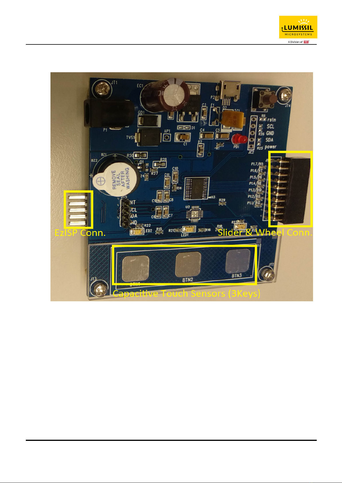
Figure 1: Photo of IS31SE5117 Evaluation Board ............................................................................................................... 4
Figure 2: Photo of Slider Board and Wheel Board .............................................................................................................. 5
Figure 3: IS31SE5117 Evaluation Board connection block diagram .................................................................................... 5
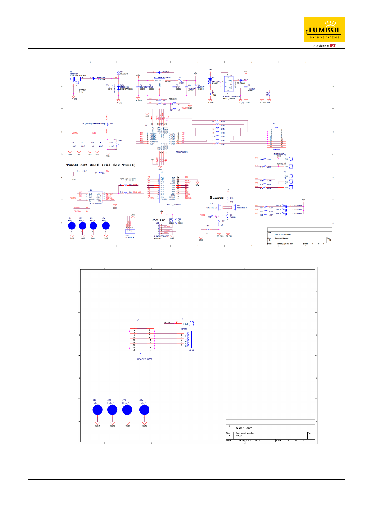
Figure 4: Schematic of IS31SE5117 Evaluation Board ........................................................................................................ 6
Figure 5: Schematic of Slider Board .................................................................................................................................... 6
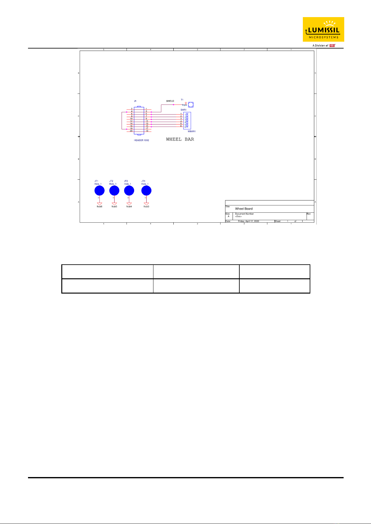
Figure 6: Schematic of Wheel Board .................................................................................................................................. 7
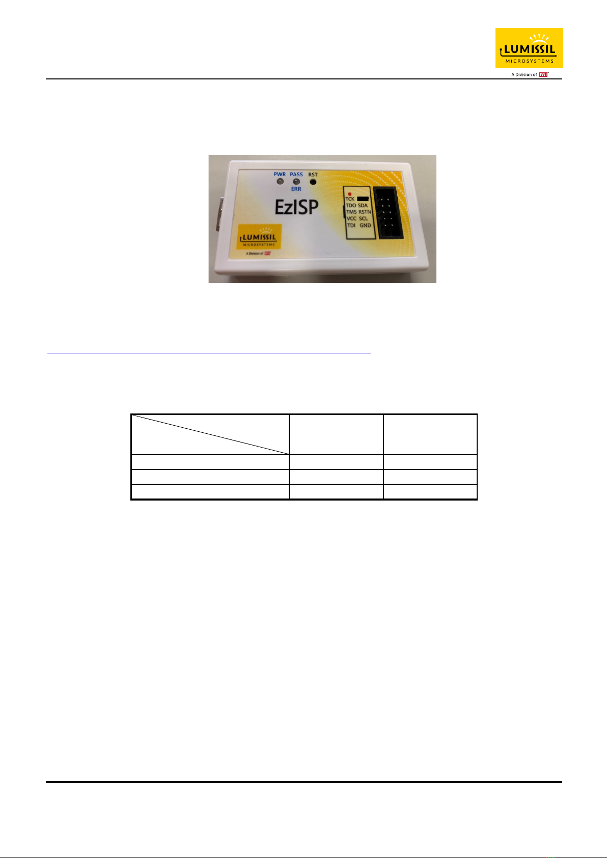
Figure 7: Photo of EzISP Board ........................................................................................................................................... 8
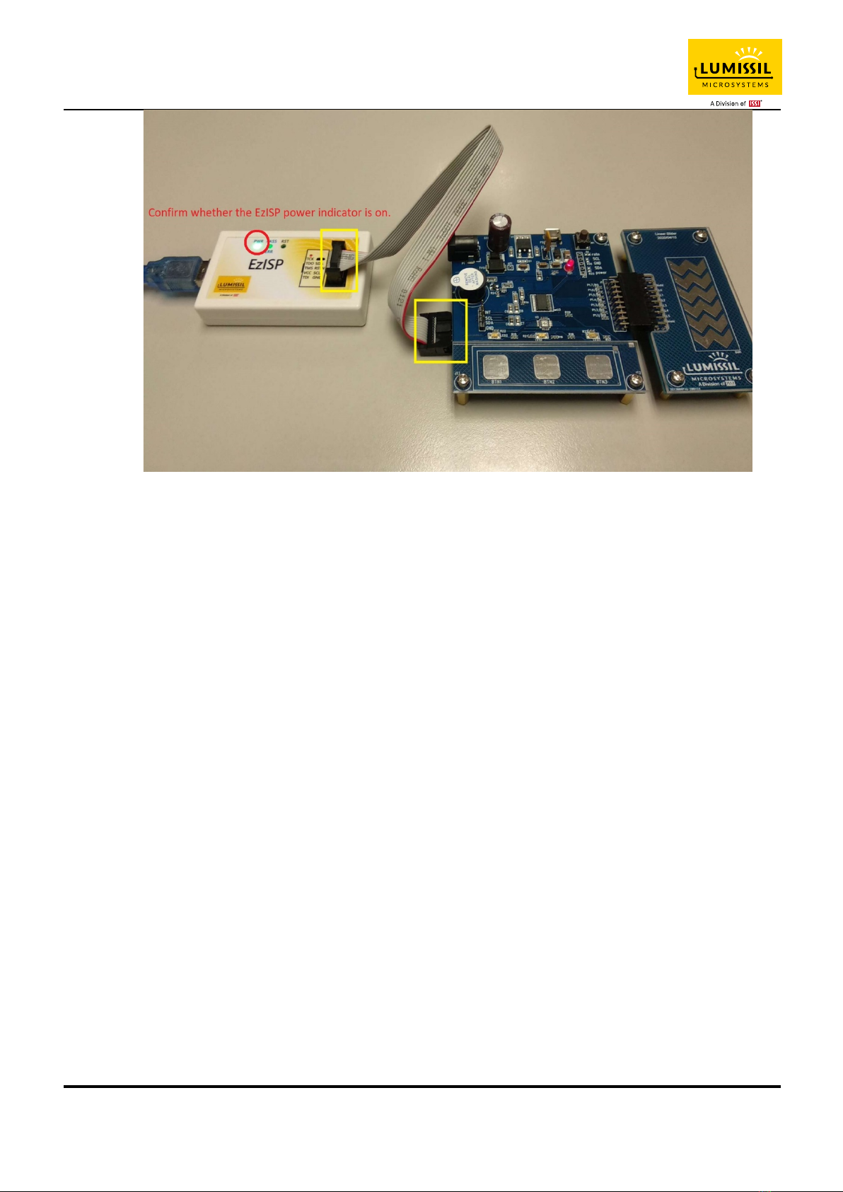
Figure 8: Connection of IS31SE5117 evaluation board and EzISP board ............................................................................ 9
Figure 9: GUI connect status shows disconnect ............................................................................................................... 10
Figure 10: GUI connect status shows connect .................................................................................................................. 10
Figure 11: GUI export/import options .............................................................................................................................. 11
Figure 12: GUI write parameters to Flash options ............................................................................................................ 12
Figure 13: GUI preset IO configuration ............................................................................................................................. 13
Figure 14: Key Variation page of GUI ................................................................................................................................ 14
Figure 15: Threshold setting ............................................................................................................................................. 14
Figure 16: Set the threshold of KEY0 ................................................................................................................................ 15
Figure 17: The VALUE of the KEY ...................................................................................................................................... 15
Figure 18: Set EN of KEY0 to disable ................................................................................................................................. 16
Figure 19: KEY's INT and INT_EN ...................................................................................................................................... 16
Figure 20: The calibration of the KEY ................................................................................................................................ 16
Figure 21: The noise lights of the KEY .............................................................................................................................. 16
Figure 22: The value of the KEY ........................................................................................................................................ 17
Figure 23: Setting page of GUI .......................................................................................................................................... 18
Figure 24: MAX_DURATION_TIME_SET option ................................................................................................................ 18
Figure 25: AUTO_CLEAR_INT_SET option ......................................................................................................................... 19
Figure 26: INTB action when AUTO_CLEAR_INT_ENABLE is disabled .............................................................................. 19
Figure 27: INTB action when AUTO_CLEAR_INT_ENABLE is enabled ............................................................................... 20
Figure 28: INTB action when AUTO_CLEAR_INT_ENABLE is enabled ............................................................................... 20
Figure 29: MULTI-KEY_SET option .................................................................................................................................... 21
Figure 30: INT_REPEAT_SET option .................................................................................................................................. 21
Figure 31: INTB behavior when setting the INT_REPEAT_SET parameter ........................................................................ 22
Figure 32: SAMPLE_AVERAGE_SET option ....................................................................................................................... 22
Figure 33: AUTO_SLEEP_SET option ................................................................................................................................. 23
Figure 34: CALIB_SET option ............................................................................................................................................ 23
Figure 35: AUTO_SLEEP_SET option ................................................................................................................................. 24
Figure 36: SCAN_SETTING option ..................................................................................................................................... 24
Figure 37: SCANNING_FREQUENCY_SET option ............................................................................................................... 24
Figure 38: SETTIN-2 parameters ....................................................................................................................................... 25
Figure 39: SETTING parameters ........................................................................................................................................ 26
Figure 40: Display the current value of KEY on the GRAPH page ..................................................................................... 27
Figure 41: Slider page of GUI ............................................................................................................................................ 28
Figure 42: Slider Bar (Open-end) and Slide Wheel (Close-end) ........................................................................................ 28
Figure 43 Slide key calibration .......................................................................................................................................... 29
Figure 44: Output Setting ................................................................................................................................................. 30
Figure 45: I2C Communication page of GUI ..................................................................................................................... 31
Figure 46: Block diagram of EzISP Board connected to the custom target board ............................................................ 33
Figure 47: Pin configuration on EzISP board ..................................................................................................................... 33

IS31SE5117 EVB User Manual
Lumissil Microsystems – www.lumissil.com 4
Rev. B, 10/25/2020
1. HARDWARE ENVIRONMENT
1.1 Appearance of Evaluation Board (EVB)
Figure 1: Photo of IS31SE5117 Evaluation Board

IS31SE5117 EVB User Manual
Lumissil Microsystems – www.lumissil.com 5
Rev. B, 10/25/2020
Figure 2: Photo of Slider Board and Wheel Board
1.2 Connection Block Diagram
Figure 3: IS31SE5117 Evaluation Board connection block diagram

IS31SE5117 EVB User Manual
Lumissil Microsystems – www.lumissil.com 6
Rev. B, 10/25/2020
1.3 Schematic of Evaluation Board
Figure 4: Schematic of IS31SE5117 Evaluation Board
Figure 5: Schematic of Slider Board

IS31SE5117 EVB User Manual
Lumissil Microsystems – www.lumissil.com 7
Rev. B, 10/25/2020
Figure 6: Schematic of Wheel Board
1.4 ORDERING INFORMATION
Part No.
Temperature Range
Package
IS31SE5117-QFLS3-EBGUI
-40°C ~ +105°C
QFN-24, Lead-free
Table 1: Ordering Information
For pricing, delivery, and ordering information, please contact LUMISSIL’s marketing and sales team at
http://www.lumissil.com/company/office-locations or (408) 969-6600.

IS31SE5117 EVB User Manual
Lumissil Microsystems – www.lumissil.com 8
Rev. B, 10/25/2020
2. SOFTWARE SUPPORT
2.1 Software Requirements
Before using the GUI, the PC first needs to install the EzISP USB driver and related files (for example: Microsoft
Framework and C++ library).
Figure 7: Photo of EzISP Board
Note: If there is no ".NET Framework" or the version lower than revision 4.0 on Windows system, ".NET
Framework" should be downloaded as below link and install it.
https://www.microsoft.com/en-us/download/confirmation.aspx?id=24872
2.2 Run GUI Program
GUI operation process is as follows:
I2C Slave Address*
AD Pin Select
Write Command
Read Command
AD = floating
0x78
0x79
AD = GND
0x7A
0x7B
AD = VDD
0x7C
0x7D
Table 2: AD pin selection and I2C slave address definition
* I2C Slave Address: 7-bit Address + 1 bit(R/W)
(1) Connect USB cable between the connector of the EzISP Board and the USB port of your PC.
(2) Use a 10-pin 2x5 Socket-Socket 2.54 mm IDC cable from the connector on the EzISP Board to the
connector on the IS31SE5117 Evaluation Board.

IS31SE5117 EVB User Manual
Lumissil Microsystems – www.lumissil.com 9
Rev. B, 10/25/2020
Figure 8: Connection of IS31SE5117 evaluation board and EzISP board
(1) Execute GUI program (file name: TouchKeyGUI_5117_rls.exe).

IS31SE5117 EVB User Manual
Lumissil Microsystems – www.lumissil.com 10
Rev. B, 10/25/2020
3. GUI INTERFACE
3.1 Connect Status
When connecting USB to IS31SE5117 EVB, first, you need to select the correct AD value. If the selected AD
value is correct, the Connect Status will be displayed as "Connect" (with a green box), and the following settings
can be selected. Otherwise, the Connect Status will be displayed as "Disconnect" (with a red box) and cannot
select any of the following settings.
Figure 9: GUI connect status shows disconnect
Figure 10: GUI connect status shows connect

IS31SE5117 EVB User Manual
Lumissil Microsystems – www.lumissil.com 11
Rev. B, 10/25/2020
3.2 Export/Import
As shown in Error! Reference source not found. below, "Export Register List" is used to export the register list
of IS31SE5117. By exporting the register list, we can save the parameters set by the GUI to the computer. "Import
Register List" is used to import the register list of IS31SE5117. By importing the register list, we can load the
parameter file of the previous GUI settings into the computer.
Figure 11: GUI export/import options
3.3 Write Parameters to Flash
As shown in Error! Reference source not found.Figure 15 below, the user can write the parameters set by the
GUI into the flash memory of the IS31SE5117 chip. After clicking the "Write Parameters to Flash Memory" on the
Menu Bar, the operation of writing parameters to Flash memory can be completed in about 4 seconds.
The embedded Flash Memory has the capability to hold saved data even if the power is turned off. When the chip
is turned on again, the parameters previously written to the flash memory will become the default values.

IS31SE5117 EVB User Manual
Lumissil Microsystems – www.lumissil.com 12
Rev. B, 10/25/2020
Figure 12: GUI write parameters to Flash options

IS31SE5117 EVB User Manual
Lumissil Microsystems – www.lumissil.com 13
Rev. B, 10/25/2020
4. IO CONFIG
4.1 IO Config Setting
When the correct AD value is selected and the Connect Status shows "Connect", it means the EVB has been
successfully connected. As shown in the green box in Figure 13, the GUI will identify and display the correct
firmware version, software version and chip part number.
As shown in the blue box in Figure 13, KEY0~KEY15 can be set as one of touch keys, Slider1, Slider2, Shield and
GPIO functions. The functions that can be set for each IO pin are mutually exclusive. AD pin can be set as
KEY15.
If the IO pin is selected as a touch key, it can be used as a button. IO pin can be set to GPIO (high) or GPIO (low).
GPIO (high) here means that the IO pin is set to output high level, and GPIO (low) means that the IO pin is set to
output low level.
Slider can choose Slider Bar (Open-end) or Slider Wheel (Close-end). Slider needs at least 6 IO pins. Users can
define IO pins according to the required functions.
Users should click Apply button located at bottom right corner to submit setting.
Figure 13: GUI preset IO configuration

IS31SE5117 EVB User Manual
Lumissil Microsystems – www.lumissil.com 14
Rev. B, 10/25/2020
5. KEY VARIATION
5.1 Operating Mode Switching
As shown by the red box in Figure 14, IS31SE5117 EVB is in normal mode, and the corresponding indicator light will turn
green. After pressing the "Sleep" button, IS31SE5117 EVB will enter sleep mode, and the corresponding indicator light
will turn red. At this time, IS31SE5117 can only be woken up by the key that has been previously set as a touch key and
the wake-up function is enabled to return to Normal Mode.
Figure 14: Key Variation page of GUI
Note: If the user sets a specific key to GPIO (high) or GPIO (low), when IS31SE5117 EVB enters sleep mode, this
key will continue to maintain its previous state.
5.2 Gain Setting
The button GAIN_SET in the blue box in Figure 14 above is used to set gain for the touch keys. The gain could be
set in 1~16 levels by pulling the scroll bar and the current gain value will be shown in bottom.
Setting gain will affect the sensitivity of all the touch keys. If gain value is set too large, high sensitivity of keys
may cause a false trigger. Therefore, the touch key gain setting should be adjusted according to the actual touch
button size and working environment.
5.3 Threshold of Key
As shown in Figure 15 below,
Figure 15: Threshold setting
THRESHOLD is used to set the threshold of keys (KEY0-KEY15). The maximum value is 127. GUI will keep 127
if input value is over 127. Input data in the corresponding box and press Enter or Tab key, or move the cursor to
another location will set up the threshold.
Put mouse on corresponding box, for example in KEY0, will show a table in the red box as shown in Figure 19.

IS31SE5117 EVB User Manual
Lumissil Microsystems – www.lumissil.com 15
Rev. B, 10/25/2020
The whole interface has prompted box for each programmable parameter.
Figure 16: Set the threshold of KEY0
The address of KEY0 THRESHOLD Register is 0x30.
KEY0_TH[6:0] are the setting bits of KEY0 THRESHOLD Register (0x30).
Threshold range is from 0 to 127.
Key will be triggered when the environmental capacitance of touch key is over key threshold.
5.4 Value of KEY
As shown in Figure 20 below,
Figure 17: The VALUE of the KEY
VALUE is the current touch key value. It shows environmental capacitance if there is no object close to touch key.
The corresponding value will be display in the box when pressing KEYs (KEY0~KEY15) on EVB. The box turns
red if value is over key threshold and it means this key is triggered.
5.5 Key and interrupt enable
Figure 18 below is an example. If you want to disable KEY0, you cannot select the check box in the KEY0 column
of the IO CONFIG page. Key enable setting could shut down any touch key. If disable the KEY0 and
KEY1~KEY15 is enabled, there is no changing by touching KEY0.
Note: If KEY is set to GPIO (High) or GPIO (low) on the IO CONFIG page, the key enable setting corresponding
to KEY will also be disabled.

IS31SE5117 EVB User Manual
Lumissil Microsystems – www.lumissil.com 16
Rev. B, 10/25/2020
Figure 18: Set EN of KEY0 to disable
Interrupt enabled setting, as shown in Figure 19 below,
Figure 19: KEY's INT and INT_EN
Checking in the box is the action of enable interrupt function, no checking means disable. INT_EN should be set
to enable first when configure key interrupt for KEY0~KEY15. INT_EN is the global interrupt setting. If it is
disabled, all keys interrupt will be turned off even though key is pressed.
Note: If KEY is set to GPIO (High) or GPIO (low) on the IO CONFIG page, the INT_EN corresponding to KEY will
also be disabled.
5.6 Key Calibration
As shown in Figure 20 below,
Figure 20: The calibration of the KEY
“0” in a box means KEY0 and “10” means KEY10. System will force calibrating the corresponding KEY by
pressing button. Please make sure there in no action on keys during calibration, or it will cause errors.
5.7 Noise Display and Threshold Setting
As shown in Figure 21 below,
Figure 21: The noise lights of the KEY
There are 16 noise lights for KEY0~KEY15. Light will be red when the corresponding KEY has noise or it will be

IS31SE5117 EVB User Manual
Lumissil Microsystems – www.lumissil.com 17
Rev. B, 10/25/2020
gray.
NOISE_TH_SET bit is noise threshold set from 0~127. Input data in the corresponding box and press Enter or
Tab key, or move the cursor to another location will set up the threshold.
When the VALUE of the sample changes more than NOISE_TH_SET, but not exceeds the key threshold setting,
the touch key will be considered to be an ambient noise disturbance. And corresponding noise display will turn
red.
5.8 KEY Value Display
The key value will be shown in the red block as Figure 22.
Figure 22: The value of the KEY
As shown in the blue box above, black line is key threshold value, gray line is key value and red line is negative
threshold value.
Key value will update the current capacitance of key. The value of KEY2 is 127 and threshold is 30. The value is
over threshold, so KEY4 value display red meaning pressed.

IS31SE5117 EVB User Manual
Lumissil Microsystems – www.lumissil.com 18
Rev. B, 10/25/2020
6. SETTING-1
As shown in Figure 23 below, the touch key related parameters are set as follows.
Figure 23: Setting page of GUI
6.1 MAX_DURATION_TIME_SET
:
Maximum Pressing Duration Time Setting
As shown in Figure 24 below,
Figure 24: MAX_DURATION_TIME_SET option
MAX_DUR_ENABLE is the maximum pressing duration time function enable. Checking is enable, no checking is
disable.
MAX_DURATION_TIME is the maximum pressing duration time setting. Unit is second. When pressing time is
over MAX_DUR_TIME, system will force calibrating the pressed key.
This function is mainly used to prevent a touch key from the environment factor. For example, the water drop is on
the touch button, which causes the touch button keep pressing status and cannot be used again.
If the maximum pressing time is set, when the touch button is pressed over programmed time, it will be force

IS31SE5117 EVB User Manual
Lumissil Microsystems – www.lumissil.com 19
Rev. B, 10/25/2020
calibration. Then the touch button can be used after being affected by the water drop.
6.2 AUTO_CLEAR_INT_SET
:
Auto-Clean Interrupt
As shown in Figure 25 below,
Figure 25: AUTO_CLEAR_INT_SET option
AUTO_CLEAR_INT_ENABLE is auto-clean interrupt function. Checking is enable.
AUTO_CLEAR_INT_TIME is auto-clean interrupt time to choose. Unit is milisecond.
When AUTO_CLEAR_INT_ENABLE is disabled, only reading 02h and 03h registers will releae the INTB pin,
otherwise it will keep low.
Figure 26: INTB action when AUTO_CLEAR_INT_ENABLE is disabled
When AUTO_CLEAR_INT_ENABLE is enabled, INTB pin will be released by reading 02h (Key Status Register1)
and 03h (Key Status Register2) registers. If 02h and 03h registers are not be read within programmed time
AUTO_CLEAR_INT_TIME (10ms~200ms), then IS31SE5117 will release INTB pin after
AUTO_CLEAR_INT_TIME time expired.
Key Release
Key Press
Key Release
INT
INT
AUTO_CLEAR_INT_ENA
BLE=DISABLE
If I2C no read 02h, 03h
AUTO_CLEAR_INT_ENA
BLE=DISABLE
If I2C read 02h, 03h
Read 02h, 03h Read 02h, 03h
This manual suits for next models
1
Table of contents
Other ISSI Motherboard manuals

ISSI
ISSI IS31LT3360 User manual

ISSI
ISSI IS31FL3218 User manual

ISSI
ISSI IS31LT3135-V1 User manual

ISSI
ISSI IS31FL3745 User manual

ISSI
ISSI IS31LT3360 User manual

ISSI
ISSI IS31FL3731 User manual

ISSI
ISSI IS31AP2031-QFLS2-EB User manual

ISSI
ISSI IS31SE5104 User manual

ISSI
ISSI IS31LT3948 User manual

ISSI
ISSI IS31AP4915 User manual
Popular Motherboard manuals by other brands

Asus
Asus M5A88-M Guide de démarrage rapide

Linear Technology
Linear Technology DC1587 Demo Manual

Quantum Design
Quantum Design KuDoz 7X manual

mikroElektronika
mikroElektronika EasyPIC Fusion v7 Schematics

Gigabyte
Gigabyte GA-890XA-UD3 user manual

Microchip Technology
Microchip Technology SAMA5D3 XPLAINED user guide