No Setup
Self conguring test set-up allows for arbitrary loading of the Device
Under Test (DUT). The DUT’s polarity, function, and orientation is auto-
matically detected. There’s no need to nd the right pin to access before
testing.
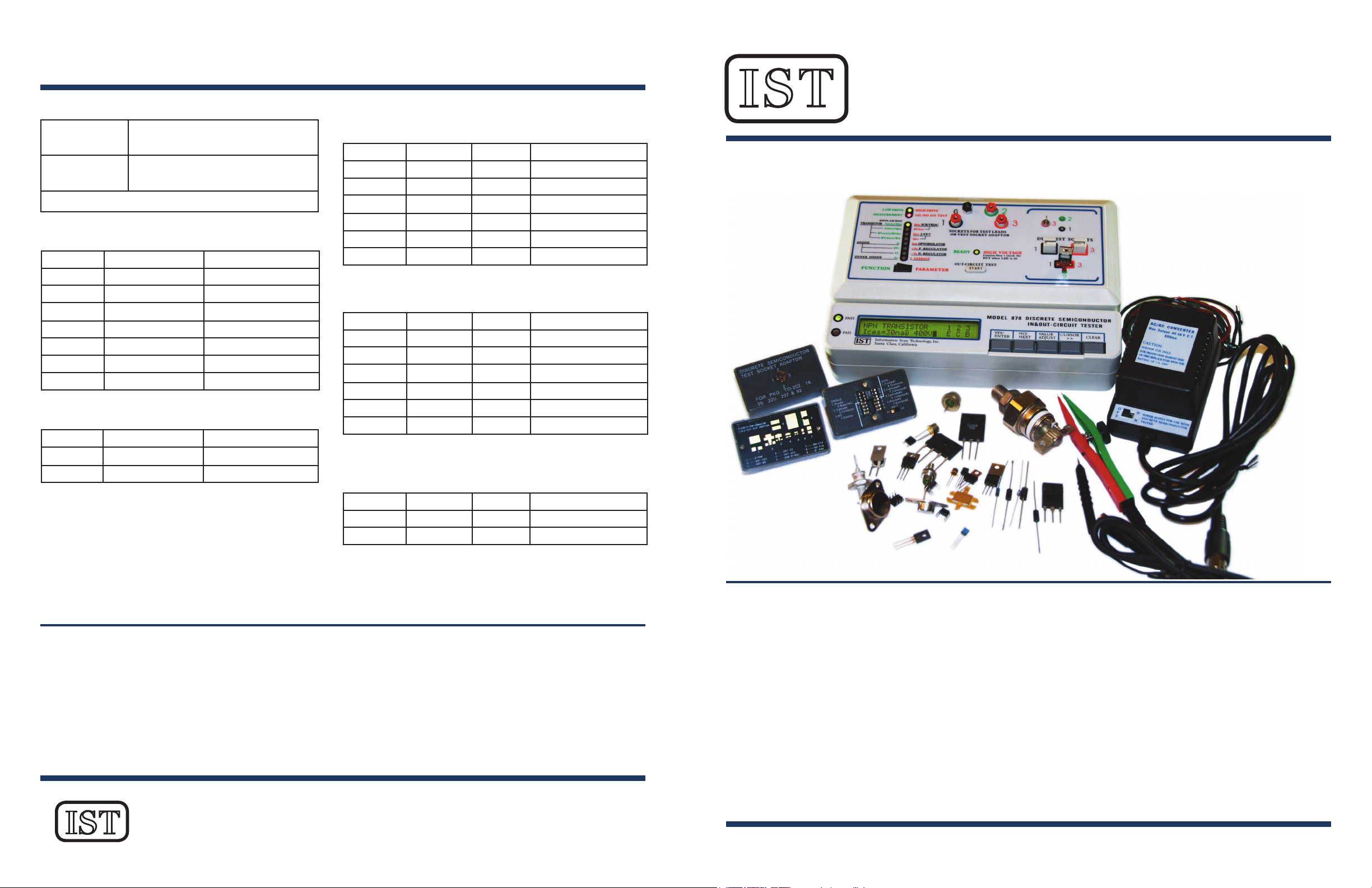
Accessible Results
Pass or fail LEDs indicators quickly shows testing result status. A backlit
LCD display shows observed measurements: parameter data, device type,
device classication, and the function or polarity of each pin.
Detects Current Leaks
Sensitive current measurement detects damaged or degraded devices with
leakage problems.
Versatile Operation
Multiple test sockets and test slot adaptor provides support for most types
of through-hole and SMD component testing.
Constant Current Sink or Current Bias
Switches between a constant current sink for regulator output loading or
current bias for measuring Diode or Zener Diode voltage.
Fingertip Test Activation
3-point probing device with ngertip test activation button makes in-cir-
cuit PCB testing fast and easy.
Programmable Voltage Source
Programmable voltage source up to 1,099 volts for breakdown voltage
and leakage current testing.
Includes 22 Types of Testing Routines.
• Bipolar Transistors (Iceo, Ices, Icbo, BVceo, BVces, BVcbo)
• MOSFETs (Idss, Igss, BVdss)
• Diodes (Ir, BVr, Vf)
• Zener Diodes (Vz, Iz)
• Thyristor (Idrm, BVdrm)
• J-FET (Idss, Igss)
• Optoisolator (Iceo)
• Regulator (+/- Vo, +/- I load)
• I leakage*
* - Measures the voltage and current across any two terminals up to
1,099V for voltage and down to the “nA” range for current. Used for
testing the clamping voltage (Vbr) of Transient Voltage Suppressors,
measuring the input impedance of a device (by OHM’s law R=V/I), or
detecting leakage current between two points (I leak).
FEATURES AND ADVANTAGES
INTRODUCING THE IST MODEL 878
PROGRAMMABLE PARAMETRIC TESTER
FOR SEMICONDUCTOR DEVICES
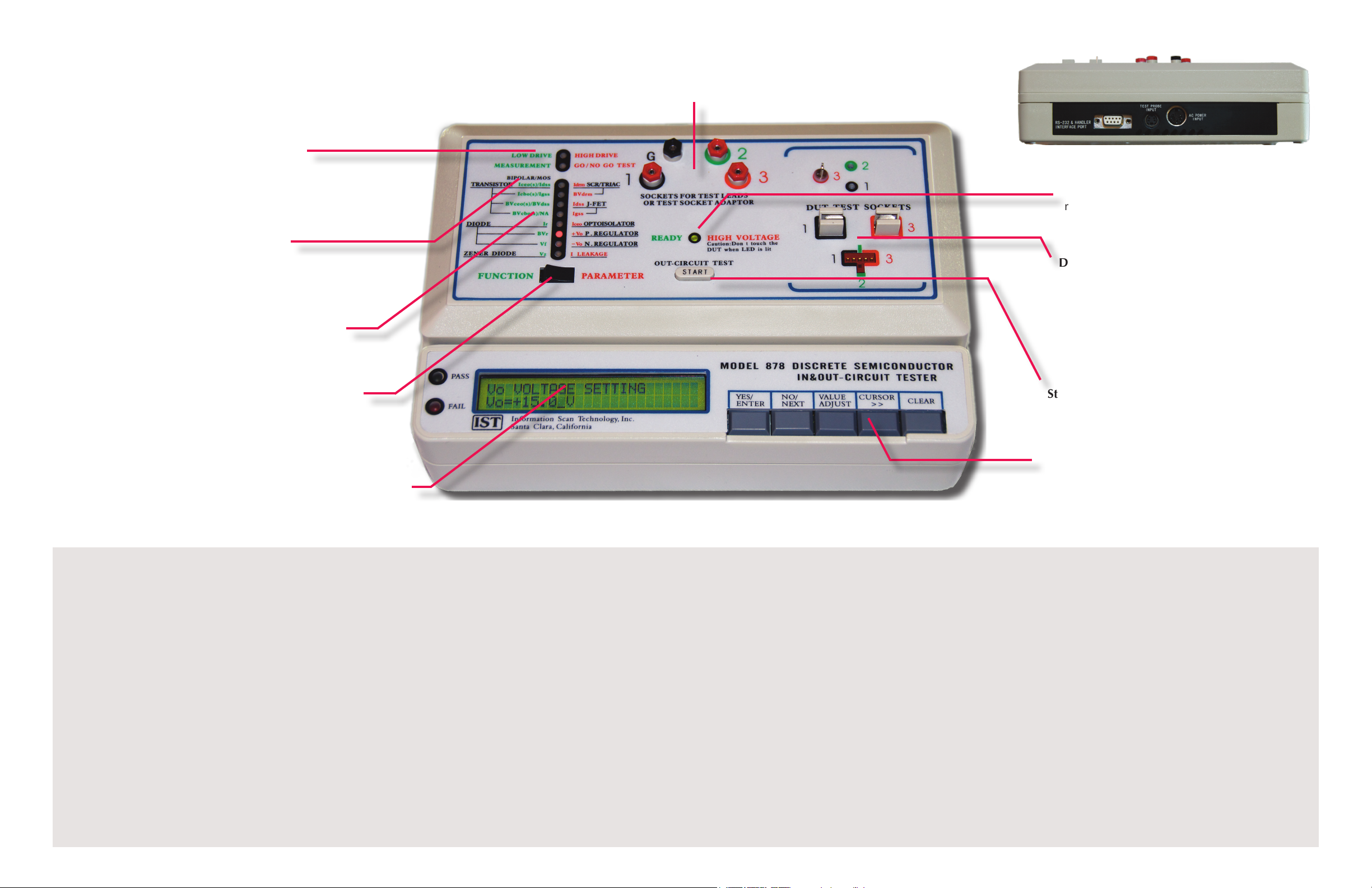
Parameter / Function Switch – Selects
between a detailed parametric test or a self-
conguring function and leakage current test
Device and Parameter Indicators – LEDs show
test settings with parameter indicated with a
green light and test type with a red light.
Measurement / Testing Mode – Indicates
current mode as measurement or Go / No
Go testing mode.
Low/High Drive – Indicates that the DUT
requires low or higher driving current in order
to pass function tests. Higher driving current
indicates DUT has poor current gain or some
degree of malfunction.
Test Adaptor Sockets – Sockets for test leads with miniature banana
plugs or test adaptors for SMD and Optoisolator testing.
Ready / High Voltage Indicator – LED turns
green when all test conditions are entered and
red to indicate when a test is in progress and
high voltage is being applied to the DUT.
Start Button – When the green “Ready” LED is
lit, this button initializes an out-circuit test.
DUT Test Sockets – The Device Under Test (DUT)
can be loaded into one of the three test sockets
in any direction without regard to the function
or polarity of each pin. Function and polarity of
corresponding pins are detected automatically
during testing and are shown on the LCD display
once the test is completed.
LCD Display and Status Indicator – The 2x24
LCD display shows user prompts, test results,
and other operating information. The Pass or Fail
LED shows the test result of a functional test or
Parametric Go/No Go Test.
Function Key Switches – Keys to select and
setup testing procedure desired. Use to choose
device type, parameters, and test condition
values. Also used to clear test settings or to
interrupt a test in progress.