T
he
reference
in
sandblasTing
T
he
reference
in
sandblasTing
1514
1046 Pressure Blaster - Instruction Manual & Parts 1046 Pressure Blaster - Instruction Manual & Parts
MAINTENANCE PROCEDURES TROUBLESHOOTING
ABRASIVE NOT FLOWING DURING BLASTING (AIR
ONLY)
Possible Causes :
1. The Abrasive Blaster is empty.
The abrasive cut-o function (if equipped) is engaged
and is preventing the abrasive from owing.
2. The MeteringValve is closed or not properly adjus-
ted.
If you suspect that a AR7+A6 Metering Valve is not
opening, conduct the following test : Shut o the Me-
tering Valve completely by turning the knob clockwise
until it stops. Next, turn it counterclockwise about 9
full turns. Then, depress the Control Handle and check
if the knob is dicult to turn or does not turn at all If so,
the Metering Valve is opening properly.
3. There is a blockage in the Metering Valve.
To free the blockage from a AR7+A6 Metering
Valve, begin by turning the knob on the Metering
Valve clockwise until it stops. Then, turn the knob
counterclockwise 9 full turns so it is fully open. Depress
the Control Handle and have a second qualied person
close the choke valve for 2 seconds and then re-open
it immediately. Minor obstructions, such as paint chips,
a bit of wet abrasive or a piece of paper, will be forced
through the Metering Valve and out the Nozzle. Turn
the Metering Valve back to the required blast setting
and check if the obstruction has been removed.
If there is still a blockage, depressurize the Abrasive
Blaster, remove the Pusher Line and the Metering Valve
and check if there is a steady stream of abrasive. If so,
allow the Abrasive Blaster to empty, and then reinstall the
Metering Valve.
If you nd a large obstruction, you will have to remove it
from inside the Pressure Vessel. To do so, start by making
sure that the Abrasive Blaster is depressurized. Next,
remove the Handway Assembly, scoop or vacuum all the
abrasive out of the Pressure Vessel, and then remove the
obstruction. You can then reinstall the Handway Assembly
and the Metering Valve. Be sure to tighten them securely.
Once this is done, you can rell the Abrasive Blaster.
It is advisable to use a screen to keep foreign objects
from getting inside the Abrasive Blaster and causing
a blockage.
4. There is wet abrasive in the Abrasive Blaster.
The wet abrasive must be removed. To do so,
depressurize the Abrasive Blaster, remove the Handway
Assembly and scoop or vacuum out the wet abrasive.
The Abrasive Blaster must always be used with dry
abrasive and supplied with clean, cool, dry air to keep
the abrasive dry. For outdoor operations, using a lid
is recommended to prevent water from getting inside
the Abrasive Blaster.
ABRASIVE STREAM TOO HEAVY OR THROBBING
DURING BLASTING
Possible Causes :
Note : When RC-176 systems rst start up, they may throb
for a while if there is an accumulation of abrasive in the
blast hose from a previous operation. This is normal, and
no corrective action is needed.
1. The Choke Valve is partially closed.
The Abrasive Blaster should be operated ONLY with the
Choke Valve fully open. Doing otherwise will cause
2. The Metering Valve needs adjusting.
Refer to the instructions on page 10 on how to adjust
Metering Valves.
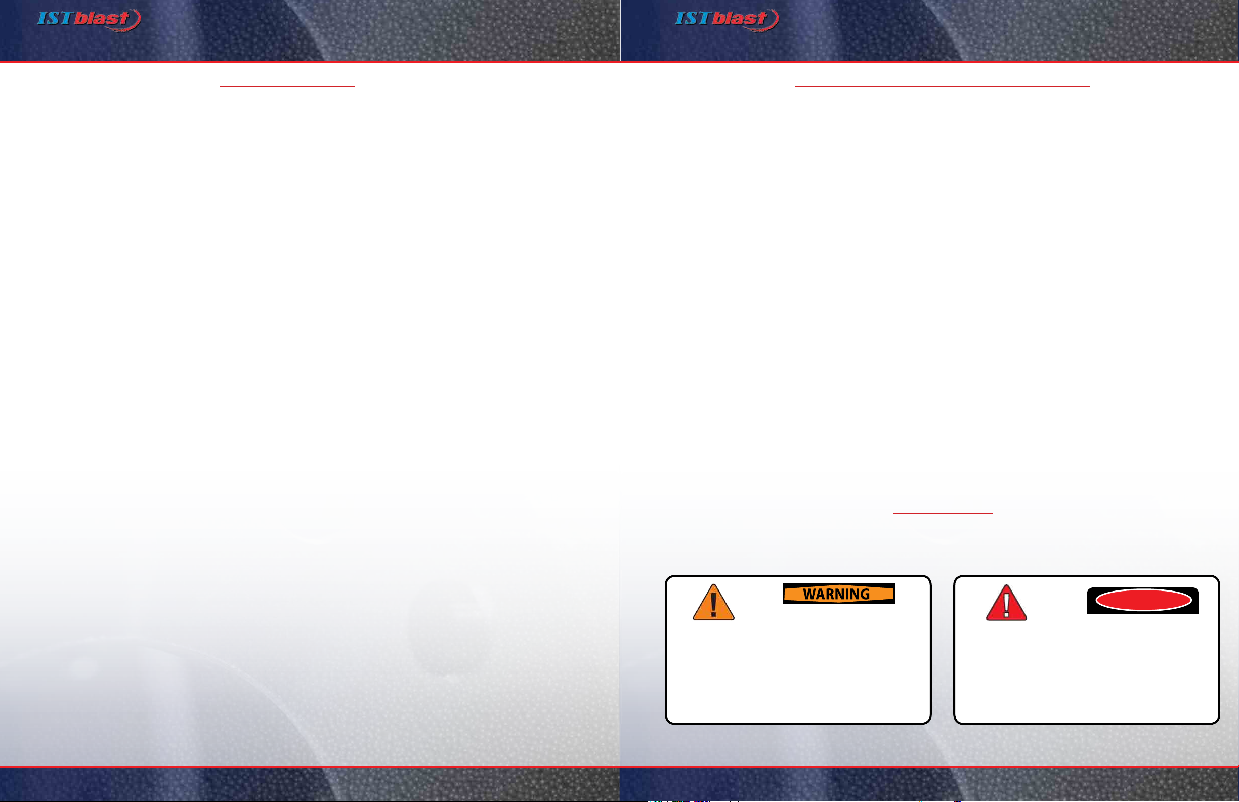
DANGER: TheAbrasive Blaster must NEVER beopened while itis pressurized.Extreme
caution is required when troubleshooting involves pressurizing the Abrasive Blaster.
Only experienced, qualied persons should perform troubleshooting procedures.
1. Inspect Personal Protective Equipment (PPE)
Inspect all PPE to make sure that it ts and that it is in good working condition. Replace or repair PPE, or
have it tted, as needed.
2. Inspect Remote Control Handles and Control Hose/Cord
Pneumatic Remote Control Systems :
Inspect the Control Handle to be sure the Safety Flap/Lever Lock/Button is in good working condition. Check for
damages, and replace or repair components as needed. Inspect the twin-line hoses and replace them if there are
leaks, abrasions or soft spots.
Electric Remote Control Systems :
Inspect the Control Handle and make sure the Safety Flap/Lever Lock/Button is in good working condition. Check
for damages, and replace or repair components as needed. Inspect the control cord and replace it if there are
damaged plug ends or signs of abrasion, exposed wires or cracks
3. Inspect Blast Hose, Couplings & Gaskets
Check the Blast Hose for leaks, abrasions and soft spots. Inspect the couplings for damage, leaks and wear. Check
the coupling gaskets for leaks and wear. Replace all components as needed. Be sure safety clips and whip checks
(safety cables) are used to secure Blast Hose connections.
4. Inspect Blasting Nozzle
Check the Blasting Nozzle for wear, and measure the bore diameter. If the bore diameter is worn to the point of
being 1/16 in. larger than its original diameter, replace the Blasting Nozzle. For instance, a #5 Nozzle (5/16 in. bore)
needs to be replaced when the bore reaches 3/8 in.
5. Inspect Air Hose, Couplings & Gaskets
Check the Air Hose for leaks, abrasions and soft spots. Check the couplings for damage, leaks and wear. Check
the coupling gaskets for leaks and wear. Replace all components as needed. Be sure safety clips and whip checks
(safety cables) are used to secure Air Hose connections.
6. Inspect & Clean Blow-down Muffler
Remove the Blow-Down Muer and turn it upside down. Tap it on a hard surface to free any debris that may be
trapped inside. Replace the muer if it is blocked and the obstruction cannot be cleared
7. Inspect Blow-down Hose Assembly
Remove and inspect the Blow-Down Hose Assembly. Replace it if you nd leaks or soft spots.
8. Inspect Pop-Up & Pop-Up Gasket
Check the Pop-up and Pop-up Gasket for wear. Replace as needed
9. Service Metering Valve
Disassemble and clean the Metering Valve. Check for worn components and make sure it is working properly.
Replace any worn components. Lubricate the MMV-175 and AR7+A6 valves with an anti-seize compound before
reassembly.
10. Service Air Valve AV-186
Disassemble and clean the valve. Check for worn components and make sure it is working properly.
Replace any worn components. Lubricate with an anti-seize compound before reassembly.
11. Service Combination Valve AV-176
Disassemble and clean the valve. Check for worn components and make sure it is working properly.
Replace any worn components. Lubricate with an anti-seize compound before reassembly.
12. Service Control Valve(s)
Disassemble and clean the valve(s). Check for worn components and make sure everything is working
properly. Replace any worn components. Lubricate with an anti-seize compound before reassembly