· The following table lists the available submenus:
Cod Descrip on
BAS Access to Base menu
ADV Accesso to Advanced menu
ALA Accesso to Alarm menu
CMD Access to Command menu
CUS Access to Custom menu
SAVE Exits saving modifica"ons.
EXIT Exits without saving (cancel)
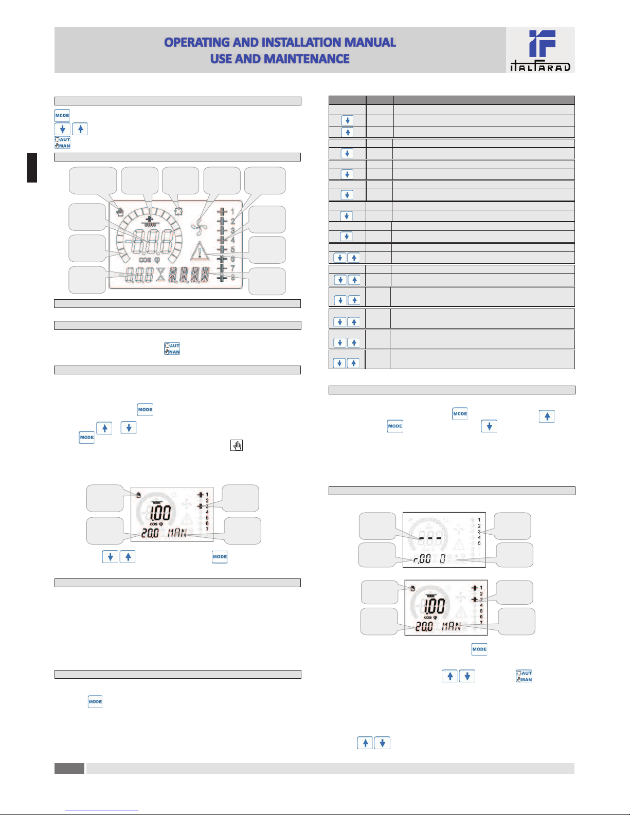
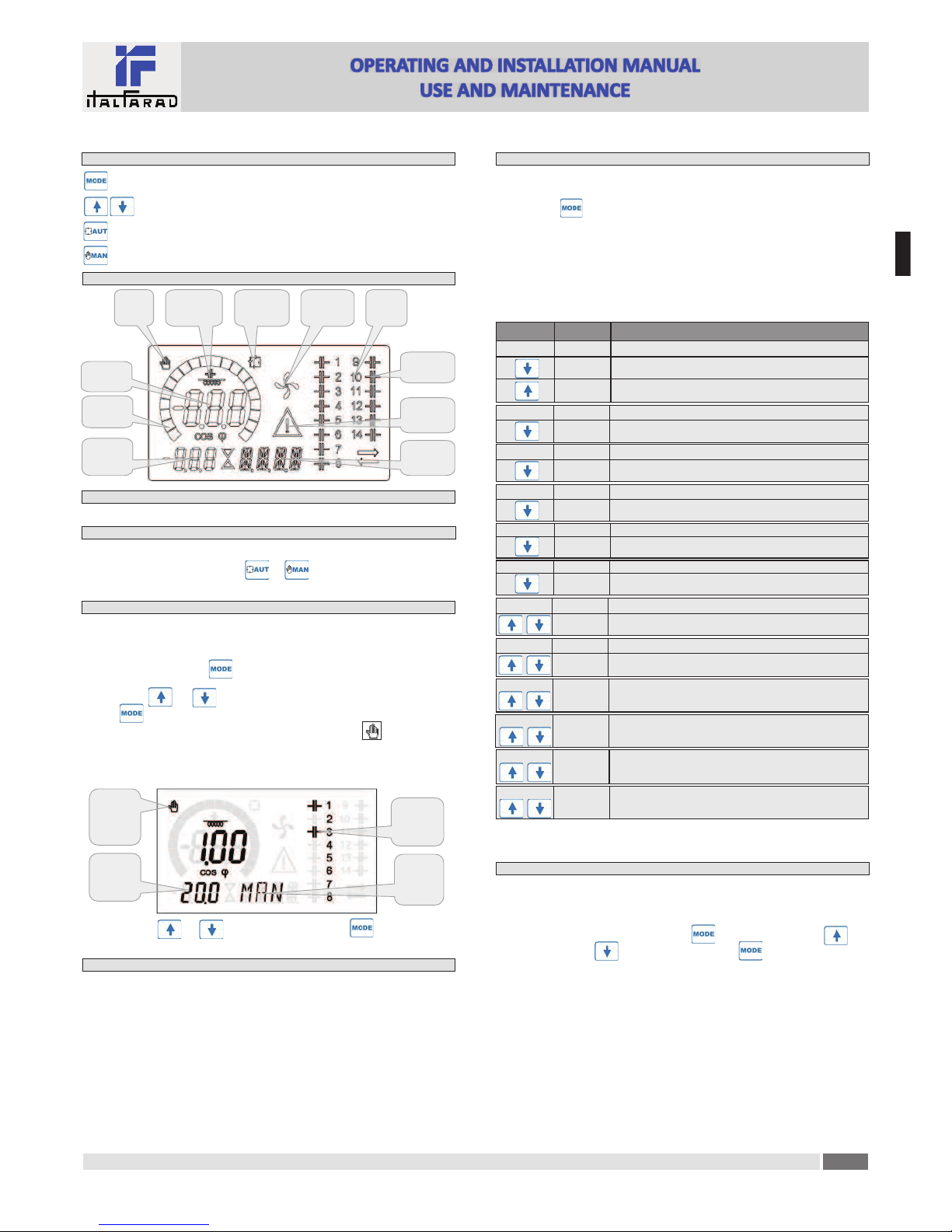
· Press to access the submenu.
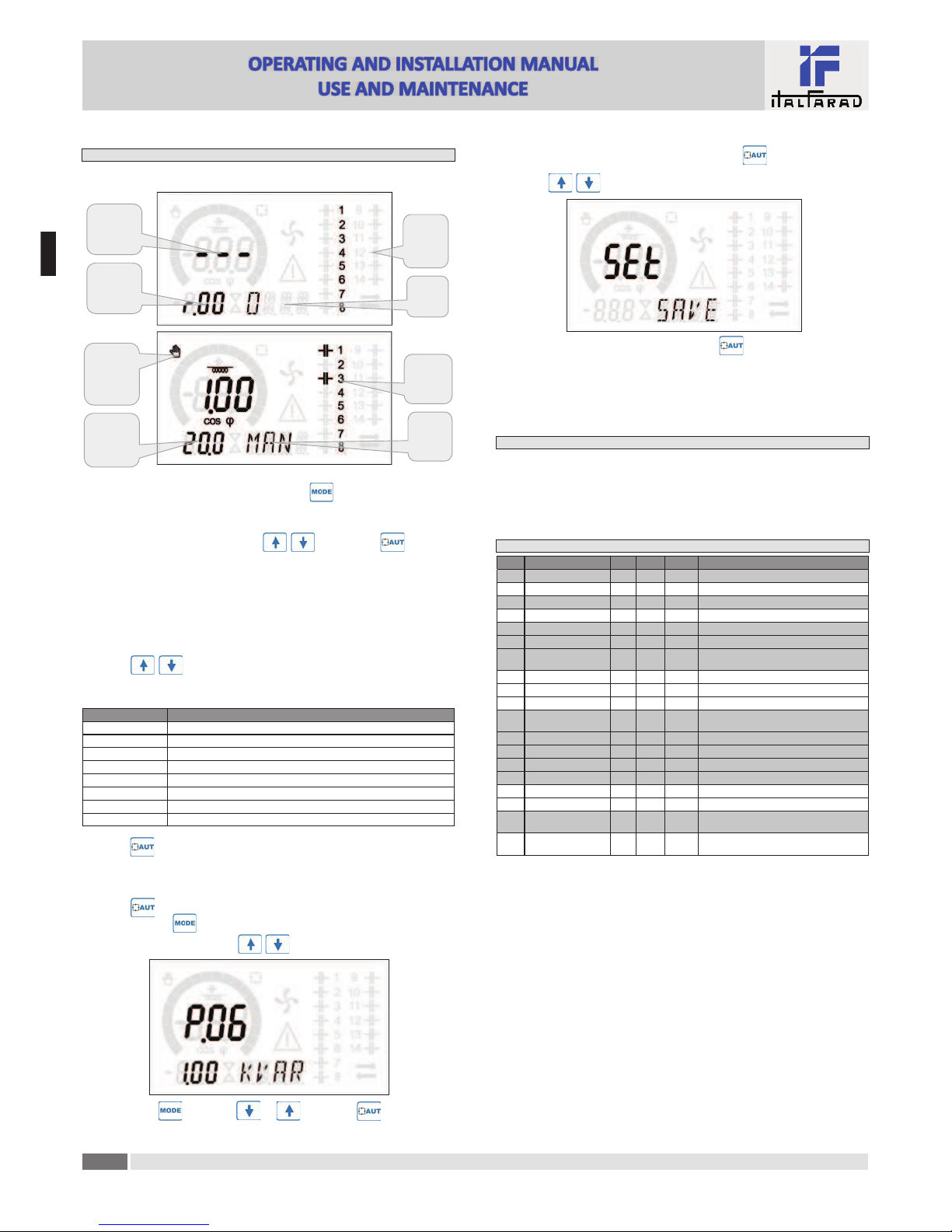
· When you are in a submenu, the main display shows the code of the selected parameter (eg P.01 ),
while the numeric/alphanumeric displays at the bo#om of the screen shows the parameter value
and / or descrip"on.
· Press to advance in the selec"on of items (such as scroll through parameters P.01 à P02 à
P03… ), or press to go back to the previous parameter.
· While a parameter is selected, with you can increase/decrease its value.
Backward Decrement/increment Forward
· Once you reach the last parameter of the menu, by pressing once more will return you to
the submenu selec"on.
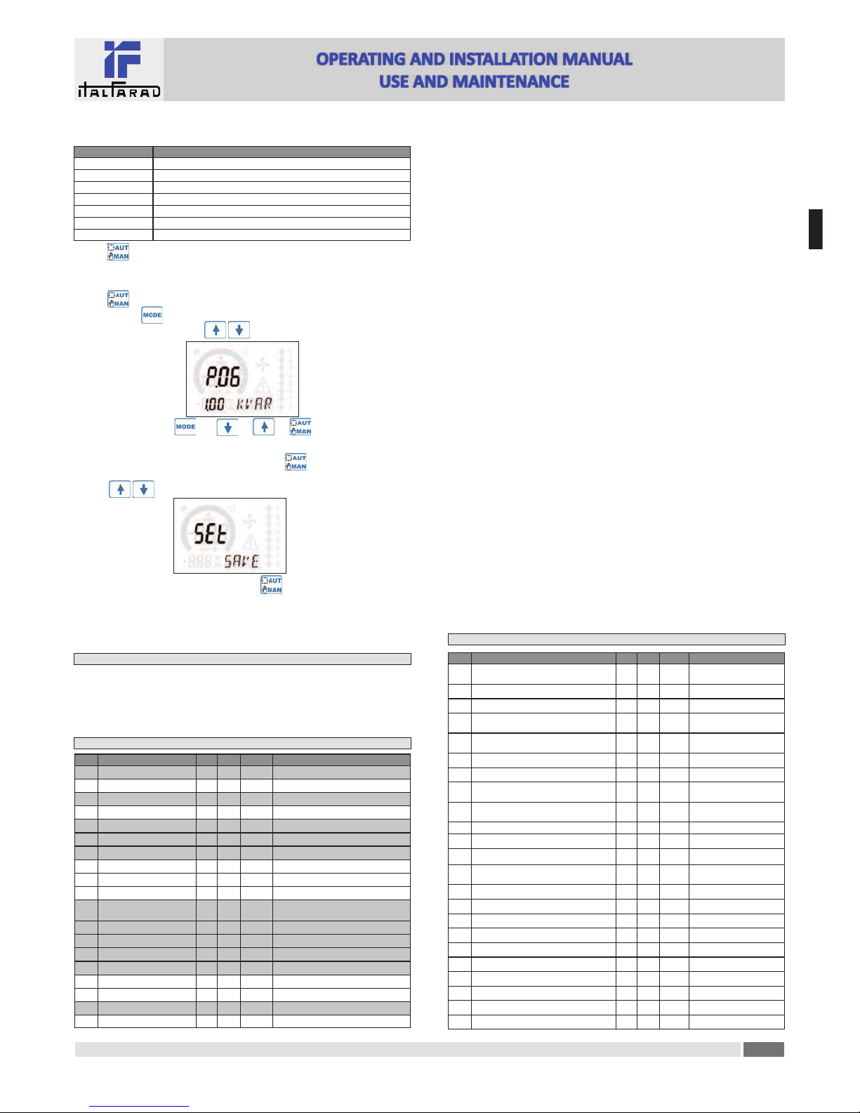
· Using select SAVE to save the changes or EXIT to cancel.
· Alterna"vely, from within the programming, holding for three seconds will save the
changes and exit directly.
· If the user does not press any key for more than 2 minutes, the system leaves the setup automatically and
goes back to normal viewing without saving the changes done on parameters (like EXIT).
· N.B.: a backup copy of the setup data (se$ngs that can be modified using the keyboard) can be
saved in the eeprom memory of the PFC96evo regulator. This data can be restored when necessary
in the work memory. The data backup 'copy' and 'restore' commands can be found in the
Commands menu.
Parameter!table
· Below are listed all the programming parameters in tabular form. For each parameter are indicated
the possible se$ng range and factory default, as well as a brief explana"on of the func"on of the
parameter. The descrip"on of the parameter shown on the display can in some cases be different
from what is reported in the table because of the reduced number of characters available. The
parameter code can be used however as a reference.
· Note: the parameters shown in the table with a shaded background are essen!al to the opera"on
of the system, thus they represent the minimum programming required for opera"on.
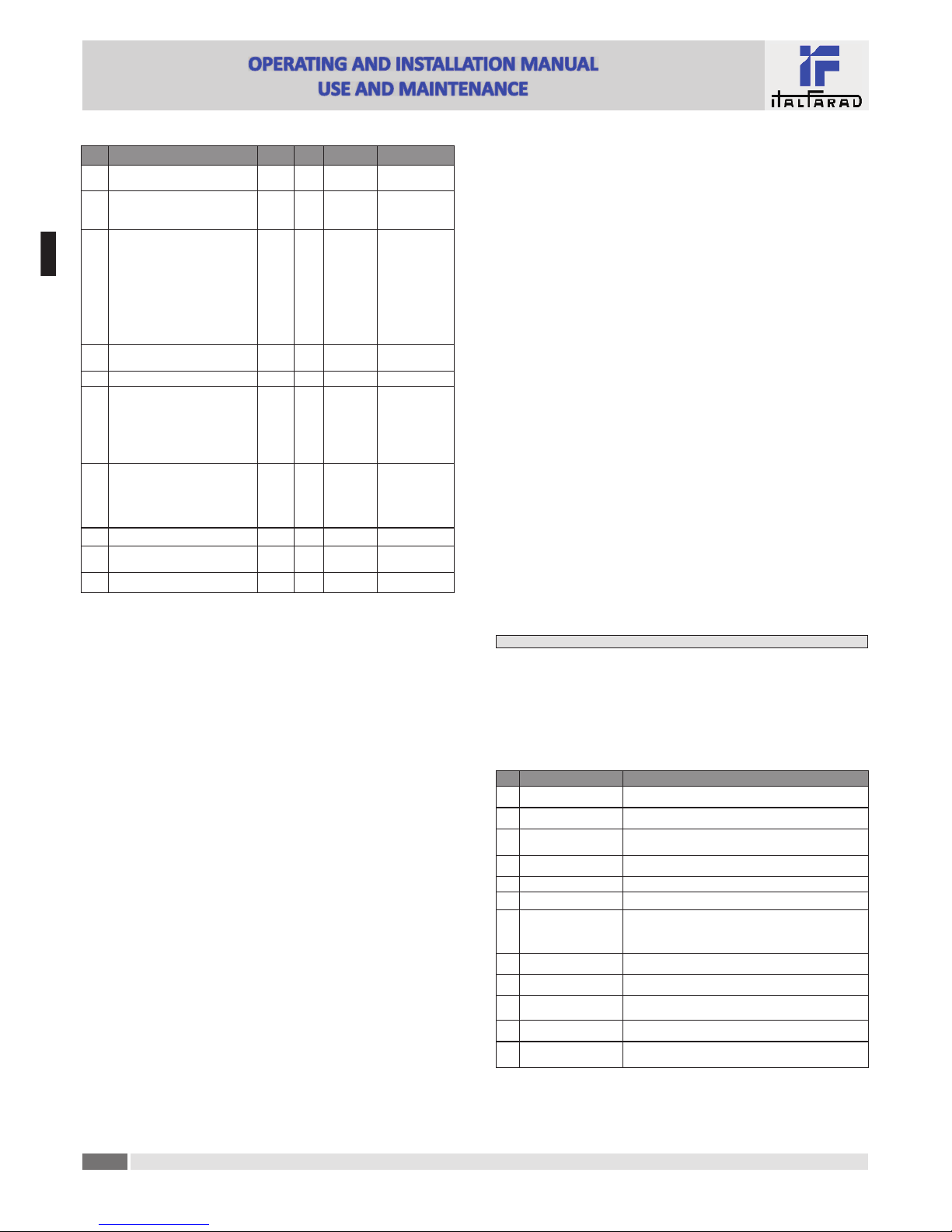
COD DESCRIPTION ACC UoM DEF RANGE
P.01 CT primary Usr AOFF OFF / 1...10.000
P.02 CT secondary Usr A51 / 5
P.03 CT read phase Usr L1 L1 -L2– L2
P.04 CT wiring polarity Usr Aut Aut -Dir -Inv
P.05 Voltage read phase Usr L2-L3 L1-L2 L2-L3 L3-L1 L1-N L2-N L3-N
P.06 Smallest step power Usr Kvar 1.00 0.10 ... 10000
P.07 Rated installa"on voltage Usr V400V 50 ... 50000
P.08 Nominal frequency Usr Hz Aut Aut -50Hz -60Hz -Var
P.09 Reconnec"on "me Adv sec 60 1 … 30000
P.10 Sensi"vity Usr sec 60 1 … 1000
P.11 Step 1 func"on Usr OFF OFF -1…32 -ON -NOA -NCA -FAN
MAN -AUT -A01…A12
P.12 Step 2 func"on Usr OFF =
P.13 Step 3 func"on Usr OFF =
P.14 Step 4 func"on Usr OFF =
P.15 Step 5 func"on Usr OFF =
P.16 Step 6 func"on Usr OFF =
P.17 Step 7 func"on Usr OFF =
P.19 Cos-phi setpoint Usr 0.95 IND 0.50 Ind – 0.50 Cap
P.20 Alarm messages language Usr ENG ENG -ITA -FRA -SPA -POR -DEU
Base!menu
P.01 -The value of the primary current transformer. Example: with CT 800/5 set 800. If set to OFF,
a&er the power-up the device will prompt you to set the CT and allow direct access to this
parameter.
P.02 -Value of the secondary of the current transformers. Example: with CT 800/5 set 5.
P.03 – It defines on which phase the device reads the current signal. The wiring of current inputs must
match the value set for this parameter. Supports all possible combina"ons of parameter P.05.
P.04 -Reading the connec"on polarity of the CT.
AUT = Polarity is automa"cally detected at power up. Can only be used when working with
only one CT and when the system has no generator device.
Dir = Automa"c detec"on disabled. Direct connec"on.
Inv = Automa"c detec"on disabled. Reverse wiring.
P.05 -Defines on which and on how many phases the device reads the voltage signal. The wiring of
voltage inputs must match the se$ng for this parameter. Supports all possible combina"ons
of parameter P.03.
P.06 -Value in kvar of the smallest step installed (equivalent to the step weight 1). Rated power of the
capacitor bank provided at the rated voltage specified in P.07 (exemple: step 10kvar-460V
supplied 400V → 10 x (400)2/(460)2→ set 7,5kvar).
P.07 -Installa"on rated voltage, which is delivered in specified power P.06.
P.08 -Working frequency of the system:
Aut = automa"c selec"on between 50 and 60 Hz at power on.
50Hz = fixed to 50 Hz.
60Hz = fixed to 60 Hz.
Var = variable, measured con"nuously and adjusted.
P.09 -Minimum "me that must elapse between the disconnec"on of one step and the subsequent
reconnec"on both in MAN or AUT mode. During this "me the number of the step on the main
page is blinking.
P.10 -Connec"on sensi"vity. This parameter sets the speed of reac"on of the controller. With small
values of P.10 the regula"on is fast (more accurate around the setpoint but with more step
swithchings). With high values instead we’ll have slower reac"ons of the regula"on, with fewer
switchings of the steps. The delay "me of the reac"on is inversely propor"onal to the request
of steps to reach the setpoint: wai"ng "me = (sensi"vity / number of steps required).
Example: setting the sensitivity to 60s, if you request the insertion of one step of weight 1 are
expected 60s (60/1 = 60). If instead serve a total of 4 steps will be expected 15s (60/4 = 15).
P11 ... P18 -Func"on of output relays 1 ... 8:
OFF = Not used .
1 .. 32 = Weight of the step. This relay drives a bank of cpacitors which power is n "mes (n =
1…32) the smallest power defined with parameter P.06.
ON = Always on.
NOA = Alarm normally de-energized. The relay is energized when any alarm with the Global
alarm property arises.
NCA = Alarm normally energized. The relay is de-energized when any alarm with the Global
alarm property arises.
FAN = The relay controls the cooling fan.
MAN = Relay is energized when device is in MAN mode.
AUT = Relay is energized when device is in AUT mode.
A01 ... A12= The relay is energized when the alarm specified is ac"ve.
P19 -Setpoint (target value) of the cosø. Used for standard applica"ons.
P20 -Language of scrolling alarm messages.
Advanced menu
COD DESCRIPTION PSW UoM DEF RANGE
P.21 Password enable Adv OFF OFF
ON
P.22 User password Usr 001 0-999
P.23 Advanced password Adv 002 (*) 0-999
P.24 Wiring type Usr 3PH 3PH three-phase
1PH single-phase
P.25 Step trimming Usr ON ON Enabled
OFF Disabled
P.26 Setpoint clearance + Usr 0.00 0 – 0.10
P.27 Setpoint clearance - Usr 0.00 0 – 0.10
P.28 Step inser"on mode Usr STD STD Standard
LIN Linear
P.29 Cogenera"on cosø setpoint Usr OFF OFF /
0.50 IND – 0.50 CAP
P.30 Disconnec"on sensi"vity Usr sec OFF OFF / 1 – 600
P.31 Step disconnec"on passing in MAN Usr OFF OFF Disabled ; ON Enabled
P.32 Capacitor current overload alarm threshold Adv %50 OFF / 0...150
P.33 Capacitor overload immediate
disconnec"on threshold Adv %83 OFF / 0.. 200
P.34 VT primary Usr VOFF OFF / 50-50000
P.35 VT secondary Usr V100 50-500
P.36 Temperature UoM Usr °C °C °Celsius ; °F °Fahrenheit
P.37 Fan start temperature Adv °25 0 .. 100°C ; (32...212°F)
P.38 Fan stop temperature Adv °20 0 .. 100°C ; (32...212°F)
P.39 Temperature alarm threshold Adv °55 50 .. 100°C ; (122...212°F)
P.41 Maximum voltage alarm threshold Adv %110 OFF / 90...150
P.42 Minimum voltage alarm threshold Adv %90 OFF / 60..110
P.43 THD V alarm threshold Adv %6OFF / 1..250
P.44 THD I alarm threshold Adv %12 OFF / 1..250
Power Factor Controller PFC96evo
E
N