4
ITALIANA SENSORI S.a.s.
5. INSTALLAZIONE
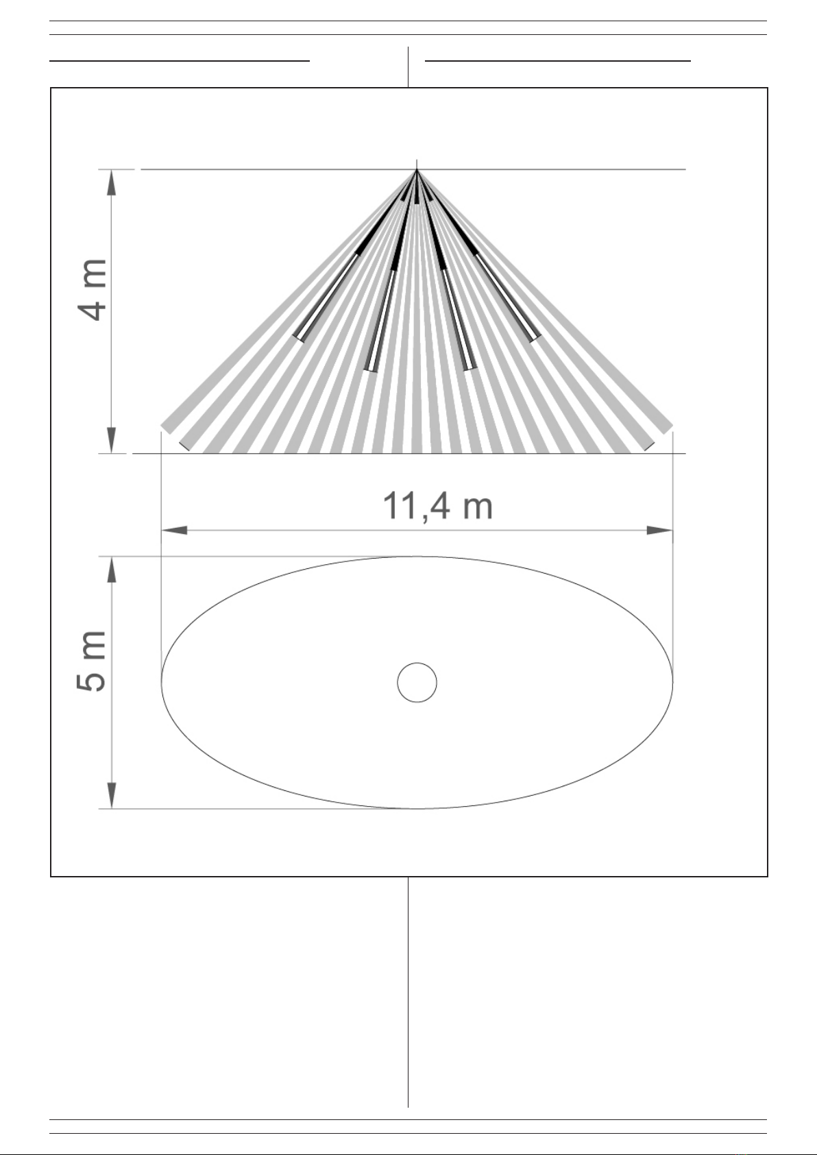
L’installazione del rilevatore è esclusivamente da softto. In
prossimitàdeiforidissaggiosonostateprevistedelleasoleche
permettonodiadattarelabasealleirregolaritàdelsoftto.
Per procedere con l’installazione, seguire i passi riportati di seguito:
• Aprire il rilevatore ruotando in senso orario la copertura (F)
• ssare il rilevatore, utilizzando le due viti Parker (E) fornite
in dotazione, nel punto che si ritiene permetta la copertura
desiderata;
• tarare il trimmer d iregolazione della microonda al ne di
ottenere la sensibilità desiderata; tenere presente che la
segnalazione di allarme avrà luogo solo quando entrambe le
tecnologie rilevano una presenza.
• Inserire la batteria (vedi capitolo memorizzazione) e chiudere
il coperchio ruotandolo in senso antiorario, facendo attenzione
di esaurire l’intera corsa.
Il rilevatore inizierà a funzionare regolarmente; per veriacare la
corretta installazione e l’area di copertura, utilizzare la funzione di
test.
6. MEMORIZZAZIONE
Per la procedura di memorizzazione, inserire la pila quando
richiesto dal manuale della ricevente utilizzata.
7. FUNZIONE TEST
Talefunzioneèstataimplementataperfacilitarelacongurazione
del rilevatore. Si può attivare togliendo il coperchio (la
successiva chiusura non provoca cambiamenti di stato);
entro un minuto la funzione verrà attivata. In questa condizione i
LEDsiattiverannoedavrannoilseguentesignicato:
• LED Rosso: si accende ad ogni trasmissione radio sia essa
un sabotaggio che una rilevazione di allarme
• LED Giallo: si accende ogni qualvolta la microonda rileva
un movimento
• LED Verde: si accende ogni qualvolta il PIR rileva un
movimento
Dopo circa 4 minuti il rilevatore esce automaticamente dalla
modalità test, i LED vengono disattivati e viene attivata la
funzione di inibizione (vedi capitolo 9 in seguito).
NOTE:
1. i LED saranno attivi esclusivamente quando il rilevatore è
in modalità test;
2. Al termine del test i LED saranno in modalità sempre
spento,perriattivarlialnedivericareilfunzionamentodel
rilevatore, occorre aprire e richiudere la copertura con lente
(apertura e chiusura dell’antisabotaggio).
3. Per provare la zona di copertura del rilevatore è importante
che il rilevatore sia chiuso e con la copertura con lente di
Fresnel inserita.
4. Una volta effettuate le prove di rilevazione e copertura radio
il rilevatore è pronto per il funzionamento, al termine della
fase di test il funzionamento del rilevatore potrà essere
vericatoinaccordoconilsistemaradioalqualeècollegato.
5. INSTALLATION
The installation of the detector is only on the ceiling. Close to
the mounting holes, some buttonhole have been provided that
allow to adapt the bottom according to the irregularities of the
ceiling. For proceed with installation, proceed as reported:
• Open the detector by turning the lid clockwise (F);
• xthedetectorbyusingthetwosuppliedparkerscrews(E)
in the point taht is supposed to give the desired coverage
area;
• set the microwave trimmer in order to get the desired
sensibility; keep in mind that the alarm transimssion will
take place only if both technologies detect a presence;
insert the battery (see chapter about the storage) and close
the lid by turning it counterclockwise, paying attention to
making sure to use up all the race.
The detector will star to works regularly; in order to verify the
correct installation and the covered area pattern, use the test
mode.
6. STORAGE
For the storage procedure, place the battery when required by
manual of the uesed receiver.
7. TEST FUNCTION
This function was implemented to facilitate conguration of
the detector. This can be activated by removing the cover
(closing it again will not cause any change in state); within
one minute the function will be activated. In this condition, the
LEDs will light up and will have the following meanings:
• Red LED: lights up with each wireless transmission,
whether it involve tampering or alarm detection.
• Yellow LED: lights up each time the microwave detects a
movement
• Green LED: lights up each time the PIR detects a movement
After about 4 minutes the detector will automatically exit the test
mode, the LEDs are turned off and stand-by mode is activated
(see the following chapter 9).
NOTE:
1. the LEDs will only light up when the detector is in test mode;
2. When the test is completed the LEDs will be in permanent
off mode, to turn them on in order to check that the detector
is working you must open and re-close the cover with lens
(open and close anti-tampering device).
3. To test the detector coverage area it is important that the
sensor be closed and the cover with Fresnel lens be inserted.
4. Once the detection and wireless range tests are completed
the sensor is ready to operate. At the end of testing,
operation of the detector can be checked according to the
wireless system to which it is connected.