28/06/2013 7CH4Q107_E_4
6
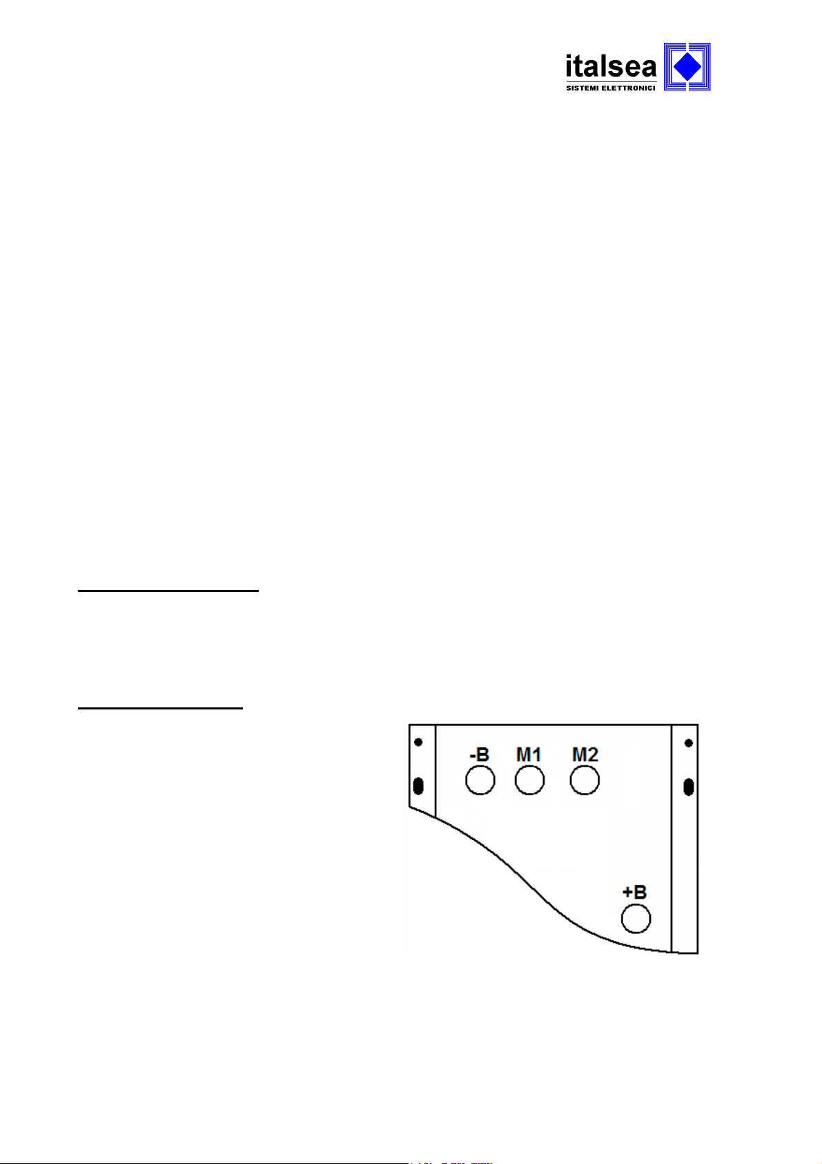
I/O CONNECTOR
16v Molex connector
(Molex p/n.39012160, contacts p/n.39000038)
fig.4
Pin 1: HI –POT. INPUT
Positive Potentiometer Supply
Pin 2: C-POT.INPUT
Central Potentiometer, or Voltage (0,5-4,5Vdc) Speed Reference Input
Pin 3: LO-POT.INPUT
Negative Potentiometer Supply, or Gnd Voltage Speed Reference Input
Pin 4: Pin 2:V_MAX (OPTIONAL)
Max speed input potentiometer (>100 KΩ).
Pin 5: PUSH
Default N.O. input contact ( +V_Batt/Pin14) for Backward safety. This input is
active when close.
Pin 6: DISABLE
Default N.C. input contact. When the contact is open the controller will decelerate
(Neutral Ramp) , will check if the motor voltage is near zero (motor stopped) and
after the electro-brake delay will inhibit the motor : appear the alarm A12 (to reset
switch-off and on again the key). If the contact will be close before the motor stop,
the machine will restart at the desired speed.
Pin 7: ELECTROBRAKE COIL ( - )
Output active low 2 Amps max (short circuit protected) and internal diode.
Pin 8: ELECTROBRAKE / HORN COIL (+)
Common +V battery for electro-brake and horn coils.
Pin 9: HORN ( - )
Output active low ( close to –Battery) for the horn or light backward direction
(2 Amps max, short circuit protected, and internal diode).