Italtecnica Sirio User manual

Rel. 1.1 07/2015
Sirio
Entry
230
Sirio
EN
F
Owner’s manual
Manuel d’instructions

3

4
WARNING
The manufacturer guarantees this product for a period of 24 months as of the date of sale; if returned, the device must be
accompanied by this handbook, with the installation date and programming parameter values entered on the last page.
The guarantee is forfeited in the event of the following: the device is tampered with, disassembled or damaged due to mishandling
and/or incorrect installation; the device is put to any other use than the one it was intended for; the device is installed in unsuitable
environmental conditions or connected to a non-standard electrical system.
The manufacturer cannot be held responsible for any kind of damage to people and/or things ensuing from failure to install the
necessary electrical safety devices upstream of the device, or as a result of unprofessional installation.
The installation and servicing of this device must be performed by specially trained personnel with the ability to understand the entire
contents of this owner’s manual
For all operations required to be carried out with the cover removed, the device must be disconnected from the power supply.
Even though there should not be any reason to remove the card, if you do so, remember that some of its parts remain live for a few
minutes after the unit has been disconnected from the mains.
The manufacturer cannot be held responsible for any kind of damage to people and/or things ensuring from the failure of any internal
safety devices to intervene, with the exception of compensation for the device itself if still under guarantee.
CAUTION: the information alongside this symbol regard installations performed according to American and Canadian
electrical standards in the relative countries
This equipment complies with the directive ROHS 2011/65/EC.
The symbol of the crossed out bin means that to safeguard the environment the equipment cannot be disposed of with
other household waste at the end of its lifecycle.
The equipment and packaging must be disposed of according to the local regulations.
READ THIS HANDBOOK CAREFULLY BEFORE INSTALLING OR STARTING THE DEVICE.

5
OVERALL SIZE - DIMENSIONS - IDENTIFICATION
DESCRIPTION
Sirio is an electronic device, employing inverter-based technology, which controls the pump stopping and starting functions.
Thanks to the particular type of technology used, it can modulate the frequency (Hz) of the motor’s input current to alter the
speed (rpm) according to the water delivery rate required from the system.
This way, the value of the pressure reaching the user appliances remains constant and the motor's absorption is always
proportional to the actual system requirements, resulting in notable energy savings over time.
SPECIFICATIONS
SIRIO 90/140Hz
SIRIO ENTRY
Power mains supply
single-phase, 230Vac ±10% - 50/60Hz
Motor output
3x230 V
1x230 V
Maximum motor phase current:
7.2 A
10.5 A
Max. line absorption:
12 A @230V
12 A @230V
Max. allowable pressure
101,5PSI (7 bar)
Max. theoretical flow rate
150 l/min –9m3/h –9000 l/h
Set-point adjustment range
0.5÷7 bar
Start pressure adjustment range
0,2÷6.7 bar
Hydraulic connection
1”¼ NPT
Enclosure
Type 3
Weight
1.6 Kg
Dimensions
254x147x143 mm
Operating ambient temperature
from +5° C to +40° C
Liquid temperature
From +5°C to +35°C

6
FEATURES
Constant pressure due to pump/motor speed regulation
Energy savings due to less pump absorption
Gradual pump start and stop reduces hammering
Protection against dry running in the event of water shortage during intake
Automatic reset in the event of dry running, with autonomous error condition recovery
Efficient leakage monitoring to protect pump in the event of repeated restarts
Anti- seize function
Intelligent overload cut-out management for a longer duration of the inverter
Digital display of pressure, current, voltage and frequency
Operation/error status signalling via LEDs and on-screen alerts display
Auxiliary contact for remote control, pair connection or double set-point
Optional I/O board for additional input and output
Soft-start can be enabled to allow a gradual start of the motor pump
Possibility of interfacing multiple devices as part of the pressurisation units (from two to four)
Operation with and without flow switch (in the event of water not perfectly clean or ferrous)
DEVICE PROTECTION FEATURES
Dry running
Overpressure
Power supply under-voltage
Power supply over-voltage
Output terminal short circuit
Motor output amperometric control
Internal overheating of the inverter (ambient temperature and IGBT temperature)
Significant leakage with continuous motor pump restarts
EMC
The product has been tested according to the standards cited in the declaration of CE compliance in one of the typical conditions
of use. Experience has however demonstrated that critical variations to the levels of EMC disturbances may occur by changing
the length of the cables, their position, the type of motor used, etc. When conditions of disturbance towards other devices occur,
contact the manufacturer to evaluate additional solutions to reduce electro-magnetic disturbance.
INSTALLATION
HYDRAULIC CONNECTION:
The Sirio must be installed on the pump delivery side, either upright or horizontally and respecting the flow direction shown by
the arrow on the cover. The pump outlet water flows through the device before being distributed to the various appliances
connected.
The water that enters the Sirio unit must not contain any impurities and/or other substances that could jam up the check valve
fitted inside it. To reduce this risk as much as possible, it is advisable to fit special filters on the intake side of the pump.
When it is not possible to guarantee the perfect cleanliness of the pumped fluid, it is advisable to deactivate operation of the
integrated flow switch (see page 25).
Install a small expansion tank (1-2 litres) after the Sirio, to limit restarts caused by any small leakages which are common in
most systems.
The pre-charge value of the tank must be suitable for the pressure values set. This will also help to keep the operation constant
in applications where water requirements are greater (e.g. for washing machines, toilet flushing systems, etc.).
On no account must a check valve be fitted between the Sirio and the motor pump or between the device itself and the user
appliances, as it could cause device malfunctions. When used with a submerged pump, the installation of a check valve before
the inverter is allowed, provided that it is positioned at least 3 metres from the inverter.
A check valve can be fitted on the motor pump intake pipe, though, to prevent it draining when the pump stops.
It is recommended that you do not install the equipment in shafts or watertight casing where heavy condensation can form.
CAUTION: when the pump stops, the conduits are still pressured so a cock must be opened to bleed the system before any
work is carried out.
Maximum cooling liquid pressure 7 bar –101,5PSI!
Maximum cooling water temperature 35 °C!
Maximum ambient temperature 40°C

7
ELECTRICAL CONNECTION:
WARNING:
- all wiring up must be carried out by specially trained personnel
- an incorrect motor pump connection could result in damage to the device or the pump motor.
- failure to comply with what is stated in this paragraph may cause serious damage to things and/or serious injuries to
people, and the manufacturer declines all responsibility.
- if the power supply cable or the cable between the Sirio and the pump is damaged, only the manufacturer of the device,
its appointee or equally qualified personnel can replace it; this is to prevent risks to things and people.
Suitable only for plastic conduits compliant with NFPA 70.
The terminal tightening torque is 4.5 Lb per In (0.5 Nm)
Use only copper wire (CU) suitable for max. 75 ° C.
LINE CONNECTION
The device has a single-phase 230 Volt 50/60Hz power line.
The electrical system to which the equipment is connected must comply with the
safety regulations in force and must therefore be equipped with:
- an automatic magnetothermal switch with high breaking capacity and with a
trigger current proportional to the capacity of the pump installed (see chart below)
- earthing with total resistance in conformity with local standards and in any case
never over 100Ω
If the device is used in swimming pools, fountains or garden ponds, an automatic
type “A” residual current operated circuit breaker (with IΔn=30mA) must always be fitted.
The system comprising the Sirio and a motor pump is considered a “fixed system”; it is therefore advisable to make
arrangements to prevent the device being disconnected from the power line it was originally connected to and mistakenly
reconnected to another source of power not equipped with the electrical protection required.
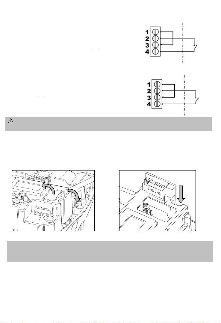
If the device is not fitted with a power lead and plug, to disconnect it from the mains install an omnipolar cut-off device with a
gap of at least 3 mm between the contacts.
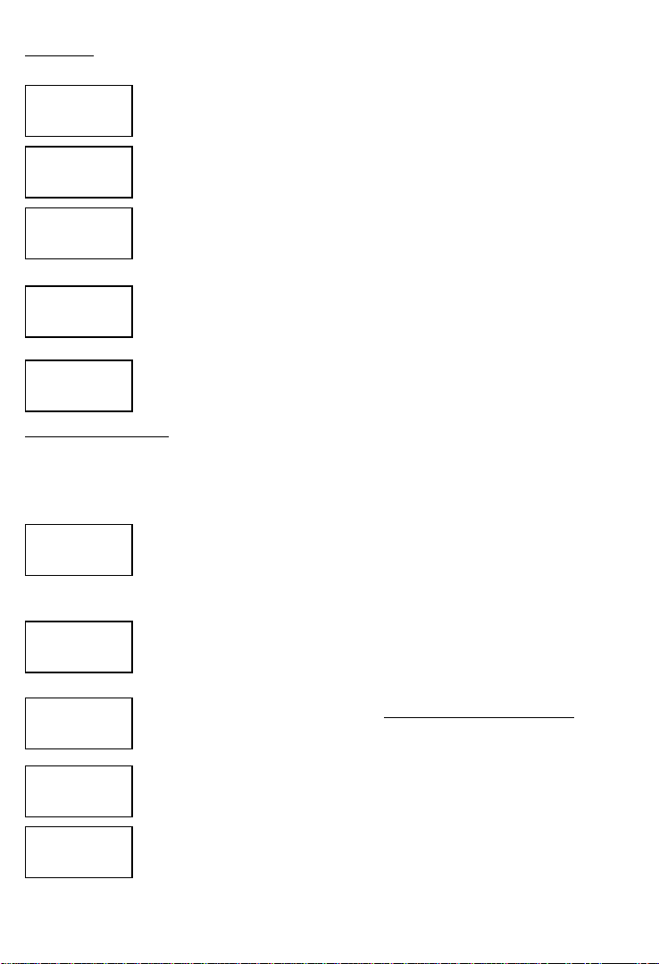
Before making the electrical connection, the cables must be
prepared with the supplied crimp terminals. Connect the two device
power wires to the 2-pole green terminal marked “LINE”; then
proceed with connection of the earth wire to one end of the double
earthing terminal using the special eyelet terminals supplied. The
faston terminals must be crimped by specially trained personnel,
using proper crimping pliers.
The recommended wire section is 1.5 mm2, which is compatible
with motor pumps up to 1.1 kW. For powers over 1.1 kW and up to 2.2 kW 2.5 mm2wire section is recommended.
If the power lead is longer than 5-10 metres, a lead with a 2.5mm2section should be used to reduce drops in the power supplied
by the lead and to reduce the chance of the under-voltage protection being triggered. The type of wire must be selected
according to the conditions of use (domestic, dry or wet, indoor or outdoor installation).
ELECTRIC PUMP CONNECTION
Equipment does not incorporate an internal overload protection for the motor load and it is intended to be used with
external or remote suitable overload protection
Before carrying out the electrical connection, is necessary to properly prepare the cables with special crimp terminals. Connect
the two power supply wires to the green bi-polar terminal on the pump motor, marked with the word "MOTOR"; then connect
the earthing cable to one end of the double earth terminal, using special eyelet terminals. The crimping of the terminals must be
carried out by specialised personnel, using proper pliers.
The device is fitted with an output short circuit protection.
The recommended cable section is 1.5 mm2for cable lengths up to 30 metres; for lengths greater than 30 metres it is
recommended to use a cable section of 2.5 mm2. The type of electrical cable must correspond to the conditions of use (use in
domestic rooms, dry or wet, for installation indoors or outdoors).
Where an excessive cable length (over 80 metres) is used, it is recommended to insert a dV/dT filter to limit peak current
voltage and safeguard the durability of the motor, particularly the windings.
Also observe the installation limits as declared by the manufacturer of the electric pump connected to Sirio
CAPACITY OF
PUMPINSTALLED
(KW)
MAGNETOTHERMAL
PROTECTION (A)
0.37 (0.5Hp)
4
0.75 (1Hp)
6
1.5 (2Hp)
12
2.2 (3Hp)
16
LINE
230V~ - 50/60 Hz
EARTH

8
AUXILIARY CONTACT
CONNECTOR
- SIRIO ENTRY (single-phase pump):
Sirio Entry can only be fitted on single-phase 230Vac electric pumps, already provided with capacitor.
When wiring up the device it is necessary to check the terminals inside the pump to ensure they are connected as prescribed by
the manufacturer of the pump. The figure below shows a typical example of connection:
- SIRIO (three-phase pump):
Sirio can be fitted on three-phase pumps with a 230Vac power supply therefore a delta configuration.
When used with a submerged pump the motor must be ordered from the manufacturer with a factory-installed delta connector.
When installing external pumps, at the time of electrical connections, ensure that the terminals inside the electrical enclosure of the
motor are connected as shown in the following figure:
AUXILIARY CONTACT CONNECTOR
WARNING: The remote connector is insulated from the network power by a “main” type insulation (basic insulation
according to EN 60730-1). Any circuit which will be connected to this terminal, will acquire the same insulation grade
from the network power. For this reason the connection must be carried out using a cable type that can guarantee the
additional insulation.
Sirio is fitted with a special connector for an auxiliary contact so that additional
functions can be exploited by interfacing the device with external equipment. The
function of the auxiliary contact depends on the setting of the “Auxiliary Contact”
parameter described in the paragraph on programming. The three operational modes,
relevant functions and connection methods are described below.
SETTING OF “AUXILIARY CONTACT” PARAMETER = “1” –Exchange function in the pressurisation units.
When the “AUXILIARY CONTACT” parameter is set on “1” the Sirio is set to work
independently (single system) or to dialogue with another partner device as part of a twin
pump pressurisation unit, depending on whether the connection cable is used. If the device
is set to work independently no connection is required. On the other hand, if the Sirio is
connected to another unit to create a pressurisation group, follow the wiring diagram
shown here; for further information on the operation as part of twin pump pressurisation
units see the “PRESSURISATION UNITS” section in the appendix.
MOTOR
1X230Vac
EARTH
MOTOR
3X220Vac
EARTH

9
SETTING OF “AUXILIARY CONTACT” PARAMETER = “2” –Remote on/off control function
When the “AUXILIARY CONTACT” parameter is set on “2” the Sirio is set to be
switched on and off by remote control according to the system requirements. This function
is useful when there is the need to programme the start of the motor pump at the same time
as other devices connected to one same control unit, for example in irrigation systems
where the pump is switched on only when the irrigation control unit activates one or more
of the system’s solenoid valve. Connect the device according to the wiring diagram shown
here, bearing in mind that when the external contact is open the Sirio shall not start the
pump even if the system reaches the Pmin value, while when the external contact is closed
the device shall operate according to the values set.
SETTING OF “AUXILIARY CONTACT” PARAMETER = “3” ––Second set-point(Pmax2) function
When the “AUXILIARY CONTACT” parameter is set on “3” the Sirio is set to adjust the
rotations of the motor pump in accordance to the Pmax2 pressure value. This function is
useful when the device must temporarily work at a different pressure to the one set in the
Pmax parameter, for example if distributors requiring different pressures are used. Connect
the device according to the wiring diagram shown here bearing in mind that when the
external contact is open the Sirio shall adjust the pump rotations according to the Pmax
pressure value , while when the external contact is closed the device shall adjust the pump
speed according to the Pmax2 value.
ATTENTION: incorrect wiring of the auxiliary contact may cause the low voltage circuit to short circuit with
consequent blowing of the fuse! Carry out the connection with particular care.
AUXILIARY I/O BOARD
To insert the auxiliary I/O board, use a flat screwdriver to lift and break the plastic window as shown in the following figure.
Then insert the expansion board, taking care to align it perfectly with the display board pins.
The connection terminal is removable and may be connected to the I/O board after having carried out the electrical connections.
The expansion board provides an auxiliary input and output. Refer to the documentation supplied with the board for the
electrical characteristics and method of connection.
CAUTION: The auxiliary I/O board is separated from the main network through a "principal" insulation type (basic
insulation according to EN 60730-1). Any circuit connected to this terminal will acquire the same level of insulation with
respect to the mains power supply. For this reason the connections must be carried out with a cable type that guarantees
the additional insulation.
EXTERNAL
CONTACT
EXTERNAL
CONTACT

10
Pmax
60 PSI
START-UP:
WARNING: do not allow the pump to run for long without water the first time it is switched on otherwise the
inverter will overheat! Prime the pump before switching on the system.
Once all the electrical connections have been made and checked to ensure they are correct, close the unit’s cover and switch on
the power.
On initial start-up the operator will be requested to enter the current as stated on the motor data plate on the following screen:
Set the value as stated in the technical specifications of the pump (in the
case of 3-phase pumps, identify the value for 230V delta connections);
press the central key to confirm and proceed with entry of the maximum
operating pressure(Pmax). After setting the pressure, press the central key
again to exit the settings menu.
The Sirio is now in stand-by; in this mode (pump stationary) all the various parameters can be set (see “programming”
paragraph) before the system is started up.
To start up the pump, simply press the “on-off” button in the centre: The Sirio will exit the stand-by mode and the motor will
start turning.
If the pump does not run or if it produces anomalous vibrations, ensure correct connection of the pump and of its capacitor in
case of single-phase pumps. For three-phase pumps also check the direction of rotation is correct.
To facilitate pump filling, the “+” button on the main screen can be pressed to force the pump up to top speed without the dry
running protection feature cutting in.
After setting all the device parameters, write the data entered in the form found at the end of this handbook for future
reference and for guarantee purposes.
PROGRAMMING
DESCRIPTION OF THE BUTTONS
Left-hand arrow: this scrolls back through the menu pages
Right-hand arrow: this scrolls forwards through the menu pages
On-Off/Reset: this switches the device from stand-by to operation mode and resets the unit in the event
of alarms and/or errors.
“+” button: this increases the value of the parameter currently shown on the display, it allows the pump to run at
top speed without the dry running protection feature cutting in.
“-” button: this decreases the value of the parameter currently shown on the display.
MAIN MANU STRUCTURE
The main menu shows the operational values of the system: pressure, current frequency of the motor, input voltage, output
current of the motor and internal temperature of the inverter. It is also possible to select the language.
Imax
0.5 Amp
1.0 BAR
[140Hz]
V= 230V
I= 5.0A
Ti= 35° C
Ta= 35° C
Language
EN

11
60 PSI
[140Hz]
60 PSI
Stand-by
V= 230V
I= 5.0A
Ti= 35° C
Ta= 35° C
Language
EN
Pmax
60 PSI
Dp.start
6 PSI
P.dr.ru.
10 PSI
Pmax2:
140 PSI
P.limit
140 PSI
DESCRIPTION OF THE PARAMETERS AND SCREEN PAGES
MAIN MENU:
These screen pages are accessible when the device is on.
Main screen page: when Sirio is operating correctly, the first line of the display shows the
instantaneous pressure detected by the system; the second line shows the current frequency of the
motor. From here, it is possible to scroll through the main menu using the arrows, or put the system
in "Stand-by" by pressing the central "on-off" key
When Sirio is in stand-by, the pump will not start up even if the pressure drops below the “Pmin”
value set. To exit stand-by, press the central button again. By holding down the “+” button, the
pump is brought up to the maximum operating speed, overriding the dry running protection (use
this function to fill the pump on initial start-up).
Voltage and current screen: on this page of the menu it is possible to view the input voltage to
the inverter and the current absorbed by the motor. The value of the output current to the motor
may differ from the value of the input current as the inverter modulates both frequency and
voltage.
Temperature screen: this displays the ambient temperatures inside the inverter and the IGBT
power module. The values of these temperatures contribute to the intelligent power management
which limits the value of the maximum frequency of the motor when the pre-alarm thresholds are
reached.
Language: The language used for the menus and the alarm messages can be selected by the user.
Use the + and –buttons to alter the parameter setting.
INSTALLER PARAMETERS:
These parameters can be found on hidden pages and usually they should only be changed in the installation phase. To access these
pages switch the device to Stand-by and keep the “+” and “-“buttons pressed down together for 5 seconds. Once you have entered the
hidden menu, use the“<<” and “>>” buttons to scroll the pages and the “+” and “-“ buttons to change the parameters. To return to the
main page press the button in the centre. Some parameters may not be displayed if the relative function is not enabled.
Pmax: this parameter enables entry of the set-point value of the device. It is a constant pressure
value required by the system (maximum pressure). During its operation Sirio regulates the revs of
the electric pump to adapt them to the actual required flow-rate, therefore maintaining the constant
pressure of the system. When it is necessary to set the Pmax to a value higher than the maximum
pump head, motor shut down on valve closure is only guaranteed if the flow switch is activated, as
Sirio switches off the pump when the flow of water passing through it falls below the minimum values (approx. 2 litres/minute)
irrespective of the pressure reached in the system.
Delta P start-up: this parameter sets the delta negative of pressure compared to Pmax for the start-
up of the pump. On opening of any type of utility, the pump will not start-up until the system
pressure has fallen below Pmax by a value equal to the delta set in this parameter. After the motor
is started up, the operating rotation speed is controlled to maintain the pressure value as close as
possible to that set in the parameter Pmax. The minimum differential settable between Pmax and Pmin is 3 PSI, with the
recommended value being at least 6 PSI.
Dry-running pressure: this parameter only affects operation with the flow switch deactivated.
Define the minimum pressure value below which, with the motor at maximum frequency, the
protection against dry-running triggers.
Pressure limit: this parameter sets the threshold for the overpressure protection intervention.
The overpressure protection intervention stops the inverter until the user resets it.
Pmax2: this parameter enables entry of the secondary set-point of the device. When the auxiliary
contact (or the auxiliary I/O board input) is closed externally, the pressure value set in Pmax2
becomes the new set-point, according to which Sirio regulates the revs of the electric pump.

12
Dp.stop
0.5 BAR
Unit
BAR
Imax
0.5 Amp
Rotat.
-->
Delta P stop: this parameter sets the positive pressure delta compared to Pmax for immediate
shutdown of the pump. During normal operation, when the valves close, the pump stops after a
time set in the parameter "stop delay". In any case, if the system pressure exceeds the Pmax value
of a delta greater than that set in this parameter, the pump will stop immediately to avoid
overpressure which may damage the system.
Unit of measurement: select the unit of measurement in BAR or PSI
Imax: this parameter enables entry of the maximum current absorbed by the electric pump in
routine conditions, to enable shut-down of the motor in the event of excessive absorption. The
motor is also shut down if the current read during operation is below 0.5 A following interruption
of the connection between the motor and Sirio. The trip time of the current overload safety device
is inversely proportional to the entity of the overload in progress; therefore a slight overload will
lead to a more delayed trip time while a more significant overload will accelerate the trip time. On activation of the device, if
the Imax parameter is set at 0.5 A (factory setting), the display automatically shows the settings page of the maximum current
and no action is permitted until the absorption limit value is set.
Rotation direction (only for three-phase pump version): this screen enables the user to invert
the direction of rotation of the electric pump without modification to the electric motor wiring. To
modify the direction of rotation of the motor, use buttons "+" and "-"; the direction indicated by
the arrow has a purely indicative value and does not reflect the actual sense of rotation which must
be verified by the installer.
ADVANCED PARAMETERS:
The advanced parameters are accessible only to the technical assistance service. For access to these parameters, it is necessary
to contact the re-seller, a technical assistance centre or the manufacturer.
The following table lists the advanced parameters for reference when technical assistance is required.
REF.
PARAMETER
DESCRIPTION
1.2
Minimum frequency
Minimum motor start-up frequency
1.3
Stop frequency
Motor shutdown frequency
1.4
Nominal motor frequency
Maximum nominal motor frequency
1.5
Switching frequency
PWM Switching frequency
1.6
Frequency correction
Maximum frequency correction
1.7
Soft-start
Soft-start activation/deactivation
2.0
Flow switch activation
Flow switch activation or deactivation
2.1
Command source
Source of manual or automatic command
2.2
Auxiliary contact function
Selection of auxiliary contact function
2.3
I/O board input function
Function of I/O auxiliary board input contact
2.4
I/O board output function
Function of I/O auxiliary board output contact
2.5
Delay on stop
Delay on shutdown after closure of utilities
2.6
Autoreset interval
Time interval between autoreset attempts
2.7
No. autoreset tests
Number of autoreset attempts
2.8
Total automatic reset
Enabling of overall reset of all alarms
3.0
Pressure calibration 0.0 Bar
To carry out calibration of the pressure sensor at 0 Bar
3.1
Pressure calibration 5.0 Bar
To carry out calibration of the pressure sensor at 5 Bar
3.2
Flow sensor calibration
To carry out calibration of the flow sensor
3.3
Pressure test
Current pressure test signal
3.4
Flow switch test
Flow switch test signal
3.5
Software Release
Release of software
3.6
Power supply timing
Inverter power supply timer
3.7
Pump timing
Electric pump operational timer
3.8
Last error
Last error occurred log
3.9
Start-up
Pump start-up counter
4.0
Vboost
Voltage boost at 0Hz
4.1
Dry run
Time delay before activation of the protection due to no water
4.2
Protection starts per hour
Activation or deactivation of the control on the number of start-ups per hour
(leak checks)
4.3
Anti-blockage protection
Activation or deactivation of a function that automatically starts up the pump
after 24 hours of disuse
4.4
Dead time PWM
Dead time PWM setting
4.5
Ki
PID controller integral constant
4.6
Kp
PID controller proportional constant
4.7
Boost time
Boost time at maximum frequency with soft start disabled

13
E0 ( 0)
Lo.Volt
E1 ( 0)
Hi.Volt
E2 ( 0)
Shortcir
E3 ( 0)
Dry run
E4 ( 0)
Amb.Temp
E5 ( 0)
IGBTtemp
E6 ( 0)
Overload
E8 ( 0)
Ser.Err.
E9 ( 0)
Ov.Pres
E7 ( 0)
OutCurve
5.0
Ta max
Maximum ambient temperature
5.1
Tm max
IGBT module maximum temperature
5.2
Ta reduction index
Frequency reduction index on ambient temperature
5.3
Tm reduction index
Frequency reduction index on module temperature
5.6
Minimum voltage
Minimum power supply voltage threshold
5.7
Maximum voltage
Maximum power supply voltage threshold
5.9
Debug Variable
Debug variable selection for process value display
ALARMS
In the event of system anomalies or malfunctions, one of the following screens will appear on the Sirio display. Each error is
coded with the letter "E" followed by a number from 0 to 13. The number which appears in brackets represents the number of
recurrences of each error. To reset an alarm, after having resolved the cause, it is usually sufficient to press the central "reset"
key or interrupt the electrical power supply for a few seconds.
E0 –Low voltage: indicates that the power supply voltage is too low. Check the input voltage value
E1 –High voltage indicates that the power supply voltage is too high. Check the input voltage
value
E2-Short Circuit: This message will appear on the screen when a short circuit is detected at the
inverter output; this may occur following incorrect connections of the electric motor, damage to the
electrical insulation in the wires which connect the electric pump to the device or a fault in the
pump's electric motor. When this error appears the electrical system should be checked as soon as
possible by specialised personnel. The error may only be removed by disconnecting the equipment from the electrical power
source and resolving the cause of the fault. Attempting to restart the inverter in the presence of a short-circuit in output may
cause serious damage to the equipment and be a source of danger to the user.
E3-Dry running: this message appears when the system is stopped following a pump intake water
shortage. If the auto-reset function has been enabled, the Sirio will carry out automatic attempts to
check for the availability of water. To clear the error status, press the central “reset” button.
E4- Ambient temperature: the error appears if the maximum internal ambient temperature of the
inverter is exceeded. Check the conditions of operation of the inverter.
E5-module temperature: the error appears if the maximum temperature of the IGBT module of the
inverter is exceeded. Check inverter operating conditions, in particular the water temperature and the
current absorbed by the pump.
E6-Overload: this alarm is displayed when electric pump absorption exceeds the maximum set
current as entered in the Imax value: this may occur following intensive use of the electric pump,
continuous restarts at close intervals, problems with the motor windings, or following problems with
the electrical connection between the motor and Sirio. If this alarm trips frequently, arrange for the
system to be checked by the installer.
E7-Out of Curve: this alarmappears if the pump operates over the maximum allowed performance.
To prevent this reduce the delivery rate and make sure the pump is running withn the nominal flow
and pressure ratings.
E8-Serial error: this alarm may occur where there is an internal serial communication on Sirio.
Contact the technical assistance.
E9-Pressure limit: the alarm intervenes when the maximum set pressure threshold has been
exceeded. If the error appears repeatedly, check the setting of the "P limit" parameter. Also check
other conditions which may have caused an overpressure (for example, partial freezing of the fluid).

14
E10( 0)
Ext.Err
E11( 0)
Start/H
E12( 0)
Err.12V
E13( 0)
Pres.Sen
E10- External error: this alarm will be displayed if, after having set the external error function on
the auxiliary I/O board, the I/O input contact is closed.
E11-Number of maximum starts/hour: this error appears if the maximum number of admissible
start-ups per hour has been exceeded. Check for the presence of any leaks in the system. Check the
pre-loading of any installed tanks.
E12- Error 12V: an anomaly has been detected in the internal low voltage power supply circuit.
Have the manufacturer check the device.
E13- Pressure sensor error: the pressure sensor has detected an incorrect value. Have the
manufacturer check the device.
POSSIBLE MALFUNCTIONS:
When one of the taps / outlets in the system is opened, the pump does not start, or there is a few seconds delay before it
starts
The DeltaP value is set too high or a check valve has been fitted downstream of the device. Try to increase the value of the start-
up pressure Pmin and eliminate any valves after the Sirio. Ensure correct operation of the external enabling contact.
When the taps / outlets are closed, the pump stops but restarts a few seconds later and there is no leakage from the
system
Dp start” value is too low, increase it.
The pump keeps switching on and off
There is leakage in the system. Check the various hydraulic connections. Check the display for pressure drops when the taps are
closed. Check the Sirio's check valve for dirt which could be preventing it from closing properly and, if necessary, clean it with
compressed air.
The device often signals 'dry running'
The pump intake pipe drains when the system is not used for some time, thereby preventing it priming the next time it is started.
If there is a foot valve fitted, check its seal.
The device often signals 'high or low voltage'
The power supply voltage may not comply with the device specifications; have it checked by qualified personnel.
The device overheats and the over-temperature protection intervenes
The inverter no longer exchanges heat with the water that runs through the device or the temperature of the fluid pumped is too
high; check for foreign bodies that block the flow of water and if necessary have the device checked by the manufacturer.
When the water flow is extremely low, the pump does not operate normally
The flow values are too low and as the device is unable to detect them, it shuts down the motor pump. Fit a small surge tank (1-
2 litres) in the system to give it more flexibility and reduce the number of restarts.
The pump does not stop
There is substantial leakage in the system or the check valve on the device is jammed by dirt; try moving the check valve with
your fingers and checking that the spring can maintain the seal.
The sensor which detects the valve position is broken. Have the device checked by the manufacturer.

15
The pump is running at top speed but performance levels are low
The pump or the capacitor connection is not correct: check the electric wiring.
The pump runs in the opposite direction (three-phase model); check rotation direction.
The pump is damaged or there is foreign matter clogging the waterway.
When more water is required of the system, the pressure drops
This is a normal condition which is due to the fact that the device is unable to force the pump above its capacity curve. As a
result, once a certain capacity is reached, the pressure is no longer offset as the pump is already running at the highest number of
revolutions allowed. In these cases, a pump with higher performance levels should be installed.
MAINTENANCE:
The Sirio is designed to keep maintenance requirements at a minimum. To guarantee the device a long working life and perfect
functionality, always follow the instructions below:
- ensure the device does not have to withstand temperatures of below 3° C; if this is not possible, make sure all the water inside
it is drained out to prevent it from freezing up and damaging the device’s plastic body;
- if the pump is equipped with intake filters, carry out regular checks to ensure they are clean;
- always ensure that the cover is closed properly and the cable conduit is tightto prevent water from penetrating from outside;
- switch off the power supply and drain the water from the system when it is going to be left unused for some time;
- do not force the pump to run without intake water, as this could damage both the pump and the Sirio;
- before using the device with any other liquids than water, contact the manufacturer.
- do not carry out any operations when the device is open
- wait 3 minutes before removing the cover from the device so the condensers can discharge.
WARNING: this device does not contain any parts that can be repaired or replaced by the end user. You are
thereforeadvised not to remove the electronic card's protective cover as this would lead to forfeiture of the guarantee!
Installation
date
…./…./…….
Stamp
Installer
Pump
make/model
Sirio serial n.

16
1.0 BAR
[ 40Hz]
1.0 BAR
S 40HzS
Installation and connection in twin booster sets
INSTALLATION: install each Sirio unit on the pressure line of the
corresponding electric pump. Connect the outlet union of each inverter to the
delivery manifold without interposing a check valve. Connect the suction of the
electric pumps to the common intake manifold, interposing a check valve for
each pump to prevent it from emptying when stopped. Sirio is compatible with
both vertical and horizontal installation.
CONNECTION: the two Sirio units are connected by an unshielded 4x0.5
mm2 cable as shown in the diagram beside. The maximum cable length is 100
cm including stripped ends.
Customers can order a preassembled connection cable with terminals and cable
numbering - Ref. SR-CBL4X05-100). If no cable is connected the device will
function in stand-alone mode.
MASTER STATUS: when the device works as a
MASTER it is sensitive to pressure changes in the plant
and thus capable of starting and stopping the pump unit
and modulating pump rpm in accordance with water
demands from the plant.
SLAVE STATUS: when the device works as a SLAVE
two capital S characters appear on the display bottom
line; in this condition if the pump is running the speed
remains constant, while if the pump is stopped its
starting is inhibited even when the taps are opened.
OPERATION: at the time of power-on the first device that gets the control over the other becomes the MASTER while the other
functions as the SLAVE. When user services are opened the MASTER device starts the pump and when the maximum rotation speed is
reached and the system pressure is lower than the preset Pmin value, it transfers control to the second inverter, which becomes the new
MASTER, while the first inverter becomes the SLAVE and its rotation speed remains fixed. With the progressive closing of the user
services the second device stops the pump and control is again transferred to the first inverter, which will stop the electric pump when
the water demand is reduced to zero after complete closing of each user. After the electric pump has been stopped MASTER status is
again transferred to the other device to ensure constant changeover of the pump that is started first. In the event of a fault or error on
one of the two inverters, the healthy device will automatically assume MASTER status and start operating in stand-alone mode. To
activate the changeover function it is not necessary to set any parameters in the menu because Sirio automatically detects the presence
of a secondary device once the electrical connection has been made.
The “Pmin” and “Dp start” values set must be the same for both devices.
SIRIO X4
It is possible to connect up to 4 Sirio inverters through the "Sirio X4" interface module. In this case, the communication cables are not
directly connected between the two inverters but are all connected to the interface module which enables them sequentially.
PROTECTION MODULE
To avoid damage to the inverter a protection module is available and may be installed on the power supply line. This will automatically
disconnect the Sirio from the electrical network in the case of power supply anomalies. Contact an authorised dealer for further
information.

17
ATTENTION
Le fabricant garantit le produit pour une durée de 24 mois à compter de la date de vente, l’appareil doit être rendu avec le présent
mode d’emploi en indiquant à la dernière page la date d’installation et les valeurs des paramètres programmés.
La garantie est annulée si l’appareil est altéré, démonté ou endommagé pour des causes imputables à une utilisation incorrecte ou à
une mauvaise installation, si l’appareil est employé dans d’autres buts que ceux pour lesquels il a été prévu, s’il est installé dans des
conditions environnementales non apropriées ou s’il est relié à une installation électronique non conforme aux normes en vigueur.
Le fabricant décline toute responsabilité provenant de dommages matériels ou physiques causés par l’absence d’installation des
dispositifs électriques de protection nécessaires en amont de l’appareil ou provenant d’une installation non effectuée dans les règles
de l’art.
L’installation et l’entretien du présent appareil doivent être effectués par du personnel spécialisé, capable de comprendre totalement
ce qui est illustré dans le présent mode d’emploi.
Toutes les opérations qui sont effectuées en retirant le couvercle du dispositif doivent être réalisées hors tensio, appareil débranché.
Puisqu’il n’existe pas de motivations concrètes pour lesquelles le retrait de la carte électronique est demandé, considérer que
certaines de ces parties restent sous tension pendant plusieurs minutes, même après le débranchement de l’appareil du réseau
électrique.
Le fabricant décline toute responsabilité pour les dommages matériels ou physiques dérivant de l’absence d’intervention de l’une des
protections internes, le dédommagement éventuel ne pouvant excéder le remboursement du montant de l’appareil même s’il est
encore sous garantie.
ATTENTION : les indications accompagnées par ce symbole concernent les installations effectuées conformément aux
standards électriques américain et canadien dans les pays relatifs.
Cet appareil est conforme à la directive ROHS 2011/65/CE.
Le symbole de la poubelle mobile barré ci-dessus indique que, pour la protection de l’environnement, l’appareil à la fin
de son cycle de vie ne peut pas être éliminé avec les déchets domestiques. Veiller à l’élimination du dispositif et de son
emballage conformément aux prescriptions locales.
LIRE ATTENTIVEMENT CE MANUEL AVANT L’INSTALLATION OU LA MISE EN SERVICE.

18
ENCOMBREMENTS - DIMENSIONS - IDENTIFICATION
DESCRIPTION
Sirio est un dispositif électronique qui contrôle le démarrage et l’arrêt d’une électropompe, basé sur la technologie à
convertisseur.
Grâce à cette particularité, il est capable de moduler la fréquence (Hz) du courant qui arrive au moteur afin d’en modifier le
régime de rotation en tours/minute selon la demande en eau de l’installation.
De cette manière, la pression aux utilisateurs arrive toujours avec une valeur constante et l’absorption du moteur est toujours
proportionnée à la demande réelle de l’installation, permettant une économie considérable d’énergie dans le temps.
DONNEES TECHNIQUES
SIRIO
SIRIO ENTRY
Tension du secteur
monophasé 230Vac ±10% - 50/60Hz
Tension du moteur
3x230 V
1x230 V
Courant maximal de phase du moteur
7,2 A (rms)
10,5 A (rms)
Absorption maxi du secteur
12 A @230V
12 A @230V
Pression maximum admissible
101,5 PSI (7 bar)
Débit théorique maximum
150 l/min –9m3/h –9000 l/h
Plage de réglage du point consigne
0,5÷7 bar
Plage de réglage de la pression de démarrage
0,2÷6,7 bar
Raccordement hydraulique
1”¼ NPT
Boîtier
Type 3
Poids
1,6 Kg
Dimensions
254x147x143 mm
Température de fonctionnement
de +5° C à +40° C
Temperature du liquide
de +5°C à +35°C
FONCTIONNALITES
Pression constante grâce au réglage de la vitesse de rotation de l’électropompe
Economie d’énergie gràce à une absorption plus faible de la pompe
Démarrage et arrêt graduels de la pompe ce qui réduit les coups de bélier
Protection contre la marche à sec en cas d’absence d’eau à l’aspiration
Réinitialisation automatique en cas d’arrêt pour marche à sec, capacité à résoudre de manière autonome la cause de la panne
Contrôle des fuites efficaces pour la protection de la pompe en cas de redémarrages trop fréquents
Fonction anti-blocage
Gestion thermique intelligente pour une plus longue durée du convertisseur

19
Indication digitale de la pression, du courant, de la tension et de la fréquence sur l’affichage
Indication des différents états de fonctionnement/erreur par des témoins lumineux et des messages sur l’afficheur
Contatto ausiliario per controllo a distanza, collegamento in coppia o doppio set-point
Scheda I/O opzionale per ingresso e uscita aggiuntivi
Soft-start sur demande pour un démarrage progressif de l’électropompe
Possibilité de relier plusieurs dispositifs à l’intérieur des groupes de pression (de deux à quatre)
Fonctionnement avec ou sans flussostat (en cas d’eau pas totalement propre ou ferreuse)
PROTECTION
Marche à sec
Surpression
Sous-tension d’alimentation
Surtension d’alimentation
Court-circuit sur les bornes de sortie
Contrôle ampèremétrique sur sortie moteur
Surchauffe interne du convertisseur (température ambiante et température IGBT)
Fuites importantes avec redémarrages trop fréquentes de l’électropompe
CEM
Le produit a été testé selon les standards cités dans la déclaration de conformité CE dans des conditions normales d’utilisation.
L’expérience a cependant démontré que de sensibles variations au niveau des perturbations électromagnétiques pouvaient
survenir en cas de modification de la longueur des câbles, de leur position, du type de moteur utilisé, etc. En cas de
perturbations sur les autres appareils électriques, contacter le fabricant afin d’envisager des solutions supplémentaires pour
réduire les perturbations électromagnétiques.
INSTALLATION
BRANCHEMENT HYDRAULIQUE :
Sirio doit être installé sur le refoulement de la pompe, en position horizontale ou verticale, en respectant le sens d’écoulement
indiqué par la flèche sur le couvercle. L’eau en sortie de la pompe traverse le dispositif pour être ensuite distribuée aux
différents utilisateurs.
L’eau en entrée du Sirio doit être exempte d’iimpuretés ou d’autres substances pouvant bloquer le mouvement de la soupape de
retenue située à l’intérieur. Pour réduire au minimum ce risque, il est utile, de monter des filtres appropriés sur l’aspiration de la
pompe.Lorsqu’il n’est pas possible de garantir la propreté totale du fluide pompé, il est conseillé de désactiver le
fonctionnement du flussostat intégré (voir page 40).Installer un petit vase d’expansion (1-2 litres) après le Sirio de manière à
limiter les redémarrages causés par d’éventuelles petites fuites, dont la présence est normale dans une grande partie des
installations.
La valeur de préchargement du vase doit être adaptée aux valeurs de pression configurées. Cette astuce permet également
d’améliorer la constance du fonctionnement en cas de demandes répétées d’eau de l’installation (par exemple machines à laver,
chasses d’eau, etc...). Il est absolument indispensable de n’installer aucune soupape de retenue entre Sirio et l’électropompe ou
entre le dispostif même et les usagers, car cela pourrait provoquer de mauvais fonctionnements de l’appareil. En cas
d’utilisation avec une pompe immérgée, l’installation d’une soupape de non retour est possible en amont du convertisseur, à
condition qu’elle soit positionnée à au moins 3 mètres de ce dernier.
Il est également possible d’introduire une soupape de retenue dans le tube d’aspiration de l’électropompe pour en éviter la
vidange au moment de l’arrêt.
Il est déconseillé d’installer l’appareil à l’intérieur de regards ou de boîtes étanches ou pourrait se produire une forte
condensation.
ATTENTION: lors de l’arrêt de la pompe, les canalisations seront sous pression et il faudra donc purger l’installation en
ouvrant un robinet avant toute intervention.
Pression maximum du liquide de refroidissement : 7 bars 101,5PSI !
Température maximum de l’eau de refroidissement 35 °C!
Température ambiante maximum 40 °C

20
BRANCHEMENT ELECTRIQUE:
ATTENTION:
- tous les branchements électriques doivent être réalisés par du personnel spécialisé
- un branchement incorect du moteur électrique peut entraîner l’endommagement du dispositif et du moteur même de la
pompe.
- le non-respect des prescriptions fournies dans ce paragraphe peut entraîner de graves dommages aux biens et/ou
personnes, pour lesquels le fabricant décline toute responsabilité.
- au cas où le câble d’alimentation ou le câble entre Sirio et l’electropompe serait endommagé, le remplacement doit être
exécuté exclusivement par le fabricant de l’appareil, soit par une personne agréée par celle-ci soit par un personnel
qualifié professionnnelement équivalent, de manière à prévenir tous risques aux biens ou aux personnes.
Adapté uniquement pour gaines en plastique conformes à NFPA 70.
Le couple de serrage des bornes est de 4,5 Lb pour In (0,5 Nm)
Utiliser uniquement avec conducteur en cuivre (CU) adapté pour 75 °C max
BRANCHEMENT DE LIGNE
L’alimentation du dispositif est de type monophasée à 230 Volt 50/60Hz.
L’installation à laquelle est branchée l’appareil doit être conforme aux normes de
sécurité en vigueur et doit donc être dotée :
- d’un interrupteur magnétothermique automatique à capacité de sectionnement
élevé avec courant d’intervention proportionné à la puissance de la pompe installé
(voir tableau ci-dessous)
- d’une connexion à la terre avec résistance totale conforme aux standards locaux
et en tout cas jamais supérieure à 100Ω.
Si l’appareil est utilisé dans des piscines, fontaines ou bassins de jardin, il est obligatoire d’installer un interrupteur différentiel
automatique de type “A” avec I∆n=30mA.
Le système composé d’une électropompe et de Sirio doit être considéré comme fixe; il est donc opportun de prendre toutes les
dispositions nécessaires pour éviter que le dispositif soit débranché de la ligne d’alimentation à laquelle il a été branché à
l’origine et pour éviter qu’il soit rebranché par erreur sur une autre source d’alimentation dépourvue des protections électriques
nécessaires.
Si l’appareil n’est pas doté de câble d’alimentation et de fiche, installer un autre dispositif qui assure la déconnexion du réseau
électrique de manière omnipolaire avec une distance d’ouverture des contacts d’au moins 3 mm.
Avant d’effectuer le branchement électrique, il faut préparer
correctement les câbles avec des cosses à sertir appropriées.
Raccorder les deux fils d’alimentation du dispositif à la borne
bipolaire verte identifiée par la mention “LINE”; procéder
ensuite avec le raccordement du câble de terre à une des
extrémités de la double borne de terre, en utilisant des cosse à
oeillets appropriées. Le sertissage des cosses doit être effectué
par du personnel spécialisé en utilisant une pince spéciale.
La section des câbles conseillée est de 1,5mm2, compatibile avec des électropompes allant jusqu’à 1,1kW. Pour des puissances
supérieures comprises entre 1.1 kW et 2,2 kW il est préféreable d’utiliser un cable de 2.5mm2.
Dans le cas de longueurs de la ligne d’alimentation supérieures à 5-10 mètres, il est préféreable d’utliser un câble ayant comme
section 2.5 mm2pour réduire non seulement les chûtes de tension dans le câble, mais aussi les possibilités d’intervention de la
protection pour sous-alimentation. Le type de câble électrique doit correspondre aux conditions d’emploi (utilisation dans des
pièces domestiques, sèches ou humides, pour pose à l’intérieur ou à l’extérieur).
BRANCHEMENTDE L’ELECTROPOMPE
Le dispositif n’intègre pas une protection surcharge pour le moteur et il est prévu pour une utilisation avec
une protection surcharge externe ou à distance.
Avant d’effectuer le branchement electrique, il faut préparer correctement les câbles avec des cosses à sertir appropriées.
Raccorder les deux filsd’alimentation du moteur de la pompe à la borne bipoloaire verte indentifiée par la mention “MOTOR” ;
procéder ensuite avec le raccordement du câble de terre à une des extrémités de la double borne de terre en utilisant des cosses à
oeillets appropriées. Le sertissage des cosses doit être effectué par du personnel spécialisé en utilisant une pince spéciale.
L’apparecchio è dotato di protezione dal corto circuito in uscita.
PUISSANCE POMPE
INSTALLEE (KW)
PROTECTION
MAGNETOTHERMIQUE
(A)
0.37 (0.5Hp)
4
0.75 (1Hp)
6
1.5 (2Hp)
12
2.2 (3Hp)
16
LIGNE
230V~ - 50/60 Hz
TERRE

21
CONNECTEUR DU
CONTACT AUXILIAIRE
La section des câbles conseillée est de 1,5mm2par longueur de câble jusqu’à 30 mètres; pour des longueurs supérieures à 30
mètres il est préféreable d’utliser un câble ayant comme section 2.5 mm2. Il type de câble électrique doit correspondre aux
conditions d’emploi (utilisation dans des pièces domestiques, sèches ou humides, pour pose à l’intérieur ou à l’extérieur).
En cas de logueurs élévées (supérieures à 80 mètres) il est recommandé d’insérer un filtre dV/dT afin de limiter les pics de
tension et préserver la durée de vie du moteur, en particulier des démarrages.
Respecter également les limitations d’installation déclarées par leconstructeur de l’électropompe à laquelle Sirio est branché.
- SIRIO ENTRY (pompe monophasée):
Sirio Entry peut être installé sur des pompes monophasées avec une alimentation de 230Vac, déjà dotées de condensateur.
Lors du branchement électrique, il est indispensable de vérifier que les connecteurs à l’intérieur de la boite à bornes du moteur
sont branchés selon les modalités prévues par le constructeur de l’électropompe. Le schéma suivant montre un exemple type de
branchement :
- SIRIO (pompe triphasée):
Sirio peut être installée sur des pompes triphasées avec une alimentation de 230Vac, avec une configuration étoile triangle.
Pour une utilisation avec des pompes immergées, le moteur doit être commandé au fabricant avec un branchement étoile triangle
réalisé en usine.
En revanche, pour des pompes externes il est indispensable de vérifier que les connecteurs à l’intérieur de la boite à bornes du moteur
sont branchés comme ci-dessous :
BRANCHEMENT DU CONTACT AUXILIAIRE
ATTENZION: Le contact auxiliaire est isolé du réseau électrique par un disjoncteur principal (basic insulation selon la
norme EN 60730-1). Tout circuit branché à cette borne aura le même degré d’isolation que le réseau d’alimentation. De
ce fait, les branchements doivent être effectués avec un type de câble garantissant une isolation supplémentaire.
Sirio est muni d’un connecteur particulier par l’intermédiaire duquel est
disponible un contact auxiliaire pour exploiter les fonctions supplémentaires,en
interfaçant le dispositif avec d’autres appareils extérieurs. La fonction accomplie
par le contact auxiliaire dépend de la configuration du paramètre “Contact
auxiliaire” décrit au paragraphe relatif à laprogrammation; les trois modalités
configurables,les fonctions et méthodes de connexion électriques correspondantes
sont décrites ci-après.
MOTEUR
1X230Vac
TERRE
MOTEUR
3X220Vac
TERRE
Other manuals for Sirio
1
This manual suits for next models
1
Table of contents
Languages:
Other Italtecnica DC Drive manuals
Popular DC Drive manuals by other brands

WEG
WEG CFW-11 Series installation guide

motortronics
motortronics VMX-Synergy Plus user manual

Gemini
Gemini GEN-PACK H-W 12M6-42000 instructions

Hafele
Hafele Classic 80-B eDrive instruction manual

Pfeiffer Vacuum
Pfeiffer Vacuum TCP 1200 operating instructions

SEW
SEW MOVITRAC LTP series operating instructions

Moog
Moog DM2020 Series Installation and startup

GFA
GFA ELEKTROMAT SI 55.10-40,00 installation instructions

Siemens
Siemens SINUMERIK 828D Turning Service manual

ZF
ZF Duoplan 2K800 operating instructions

Danfoss
Danfoss VLT AutomationDrive FC 303 instruction manual

StepperOnline
StepperOnline DM556T user manual