manuals.online logo
Brands
  1. Home
  2. •
  3. Brands
  4. •
  5. ITC
  6. •
  7. Light Fixture
  8. •
  9. ITC elio TPB Configuration guide

ITC elio TPB Configuration guide

3030 Corporate Grove Dr • Hudsonville • MI • 49426
Phone: 616-396-1355 • www.itc-us.com • [email protected] • 710-00127 • REV E 02/03/20
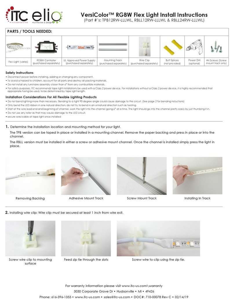
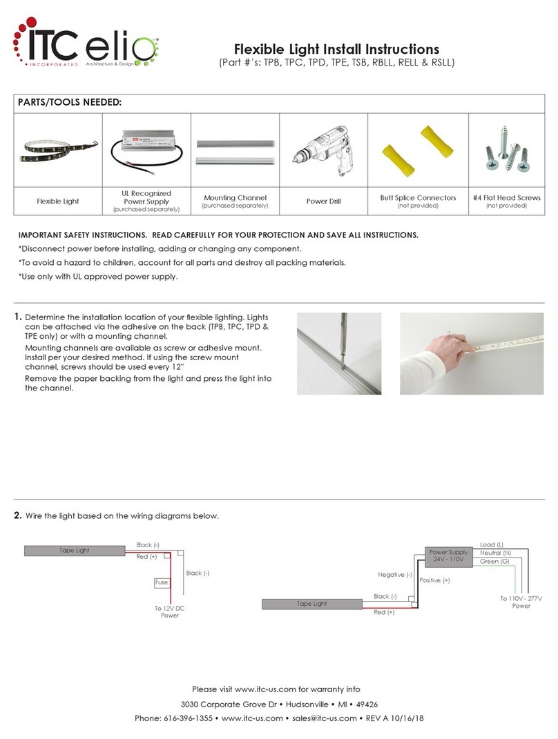
Flexible Light Install Instructions
(Part #’s: TPB, TPC, TPD, TPE, TPH, TSB, *RBLL (*channel mount only), RELL & RSLL)
IMPORTANT SAFETY INSTRUCTIONS. READ CAREFULLY FOR YOUR PROTECTION AND SAVE ALL INSTRUCTIONS.
• Disconnect power before installing, adding or changing any component.
• To avoid a hazard to children, account for all parts and destroy all packing materials.
• Use only with UL approved power supply.
Please visit www.itc-us.com for warranty info
INSTALLATION CONSIDERATIONS:
• It is recommended that fuse protection be added to the positive (+) input.
• Do not bend lighting more than necessary. It should only be bent to a 1” radius. Bending to a tight 90◦angle could cause damage to the
circuit.
• Only bend the LED ribbon in one natural direction, do not try to bend in an unnatural direction such as twisting.
• Make sure surfaces are smooth, clean and free of dust and debris before installing this product. Surfaces should be cleaned and primed
per the 3M specied cleaning instructions* on page two. Failure to properly clean the surface may result in loss of adhesion.
• Rough surfaces may prevent proper adhesion. If adhesion failure occurs, screw-in mounting channels may be used for installation.
Contact ITC sales for more information on mounting channels: 616-396-1355 / [email protected].
• RBLL exible lighting must be installed in a channel.
DO NOT INSTALL ON ROUGH PLYWOOD
Recommend use of mounting channel
TPB-1 or TPB-2
DO NOT TWIST DO NOT INSTALL ON A ROUGH EDGE
Recommend use of mounting channel
TPB-1 or TPB-2
PARTS/TOOLS NEEDED:
Flexible Light UL Recognized Power Supply
(purchased separately)
Mounting Channel
(purchased separately)
Power Drill
(not provided)
Butt Splice Connectors
(not provided)
#4 Flat Head Screws
(not provided)
Alcohol Wipes
(not provided)
Primer 94
(not provided)
3030 Corporate Grove Dr • Hudsonville • MI • 49426
Phone: 616-396-1355 • www.itc-us.com • [email protected] • 710-00127 • REV E 02/03/20
5. Wire the light based on the wiring diagrams below.
4. If using mounting channels for installation, they are available in screw or adhesive
mount. Install per your desired method.
Screw Mount Channel: Screws should be used every 12”.
Adhesive Mount Channel: Follow the same cleaning instructions above and remove
paper backing from channel and press in place.
Both Channels: Remove the paper backing from the light and press the light into the
channel.
Tape Light
Red (+)
Black (-)
Green (G)
Power Supply
24V - 110V
Neutral (N)
Load (L)
To 110V - 277V
Power
Positive (+)
Negative (-)
Tape Light
To 12V DC
Power
Black (-)
Red (+)
Black (-)
Fuse
*http://www.3m.com/3M/en_US/bonding-and-assembly-us/resources/full-story/?storyid=b3996cbd-9954-455f-8e72-88e452ca38c0
2. Apply Primer 94 as recommended by 3M.
Failure to follow the surface preparation guidelines will void
the warranty.
1. Clean surface with a mixture of 50% water/50% isopropyl alcohol.
Let surface dry.
+ +
50% 50% USE A CLEAN RAG
=MOUNTING
SURFACE
USE A CLEAN RAG
+=MOUNTING
SURFACE
3. Remove paper backing and rmly press light in place.
DO NOT slide or drag thumb along tape light or the silicone may be pulled off.
3030 Corporate Grove Dr • Hudsonville • MI • 49426
Phone: 616-396-1355 • www.itc-us.com • [email protected] • 710-00127 • REV E 02/03/20
6. Please review the considerations below to ensure a successful installation.
Only bend the wireDo not bend right at
solder joint
Do not horizontal bend to a radius of less than 11.8”
R11.8”
Do not bend exible light at 90° Do not bend to a radius of less than 1/2”
R0.59”
Do not axial bend to the height
of more than 0.312” within 0.78”
segment
0.78”
Less than 0.312”
Do not twist more than 90° over the length
of one 24V segment / Two 12V segments
(4” total length)
4”
Axis
*Flexible light cannot be eld cut. Field cutting the light will void the warranty.

This manual suits for next models

8

Other ITC Light Fixture manuals

ITC elio TPB Configuration guide

ITC

ITC elio TPB Configuration guide

ITC elio VersiColor TPB12RW-LLLWL Configuration guide

ITC

ITC elio VersiColor TPB12RW-LLLWL Configuration guide

Popular Light Fixture manuals by other brands

Philips Calculite 8044 specification

Philips

Philips Calculite 8044 specification

Bomma Orbital BOM890424 installation manual

Bomma

Bomma Orbital BOM890424 installation manual

Chauvet Professional WELL Pad user manual

Chauvet Professional

Chauvet Professional WELL Pad user manual

Lightolier Lytespan 8608 specification

Lightolier

Lightolier Lytespan 8608 specification

Griven VESUVIO OS CYM 250 HFT owner's manual

Griven

Griven VESUVIO OS CYM 250 HFT owner's manual

ABB Stanilite Nexus LX installation manual

ABB

ABB Stanilite Nexus LX installation manual

Rasha Penta Exterior V18 Profile User instructions

Rasha

Rasha Penta Exterior V18 Profile User instructions

Inspire Outflexi HV2131-30-2M(4K)E instruction manual

Inspire

Inspire Outflexi HV2131-30-2M(4K)E instruction manual

Altman Spectra CYC UV 50 Service & parts manual

Altman

Altman Spectra CYC UV 50 Service & parts manual

ProLights PIXIEZOOM user manual

ProLights

ProLights PIXIEZOOM user manual

Home Accents Holiday TY052-1924-1 Assembly instructions

Home Accents Holiday

Home Accents Holiday TY052-1924-1 Assembly instructions

SELF Electronics FLEX instruction manual

SELF Electronics

SELF Electronics FLEX instruction manual

Lightolier ProSpec 28B70E specification

Lightolier

Lightolier ProSpec 28B70E specification

JUNO NaviLite NXPC Series installation instructions

JUNO

JUNO NaviLite NXPC Series installation instructions

Eiko VRT1 installation instructions

Eiko

Eiko VRT1 installation instructions

Cooper Lighting NEO-RAY 23DS manual

Cooper Lighting

Cooper Lighting NEO-RAY 23DS manual

EuroLite LED Neon Flex user manual

EuroLite

EuroLite LED Neon Flex user manual

Blooboost 545601302 manual

Blooboost

Blooboost 545601302 manual

manuals.online logo
manuals.online logoBrands
  • About & Mission
  • Contact us
  • Privacy Policy
  • Terms and Conditions

Copyright 2025 Manuals.Online. All Rights Reserved.