3
© 2018 ITEL SNC
Table of contents
Section 1 Introduction 6
................................................................................................................................... 61 Review
......................................................................................................................................................... 6Patent
................................................................................................................................... 72 Warnings
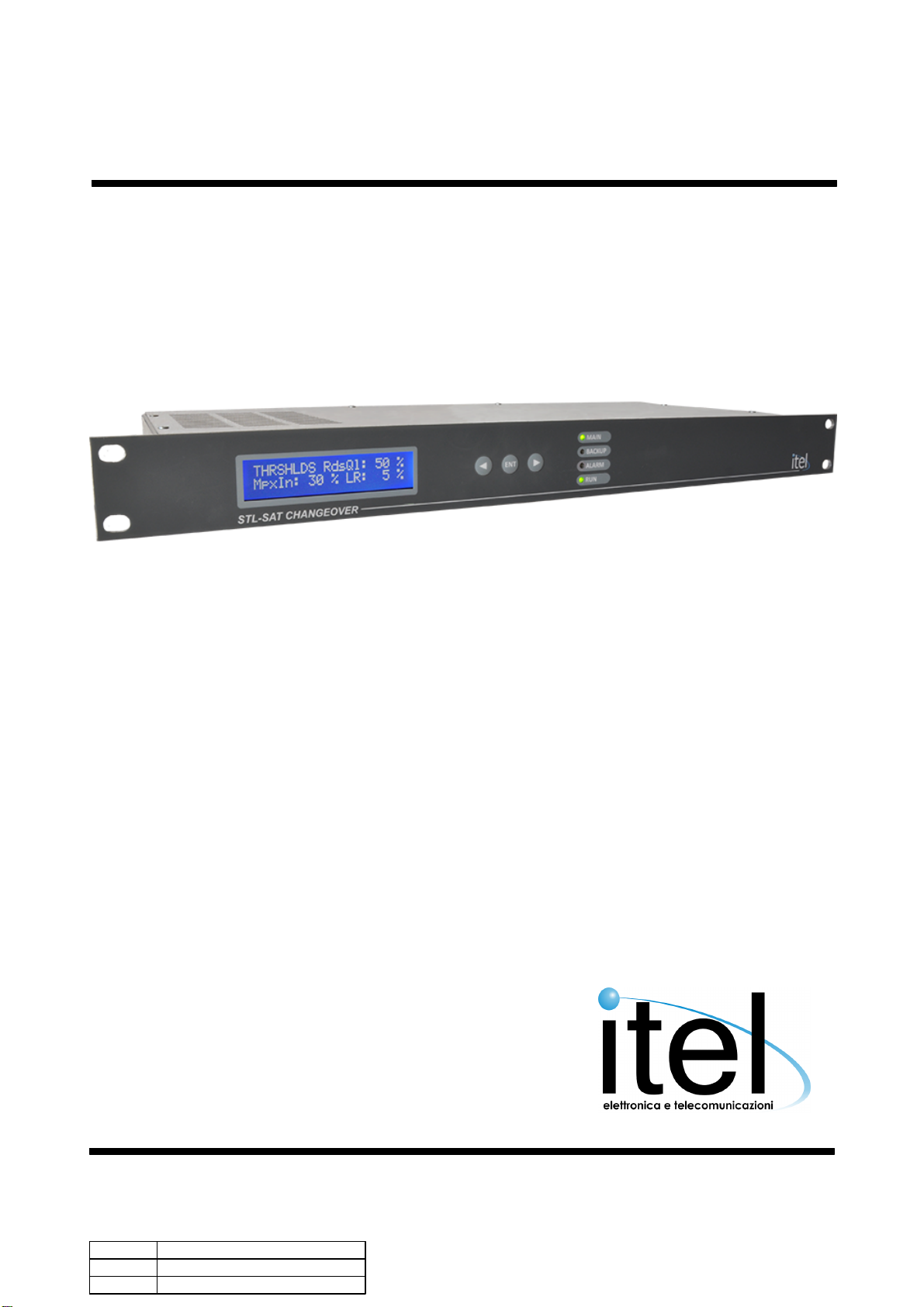
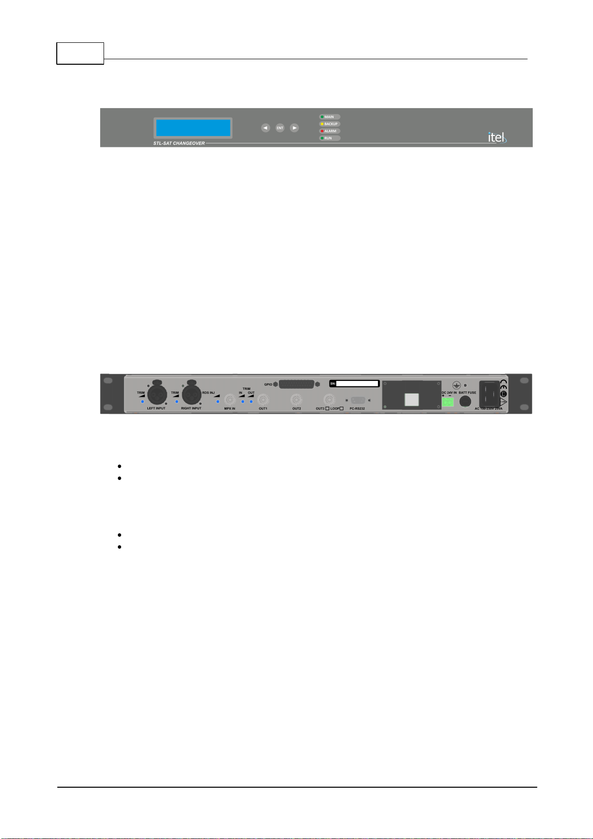
................................................................................................................................... 83 Front Panel
................................................................................................................................... 84 Rear Panel
................................................................................................................................... 95 Connectors
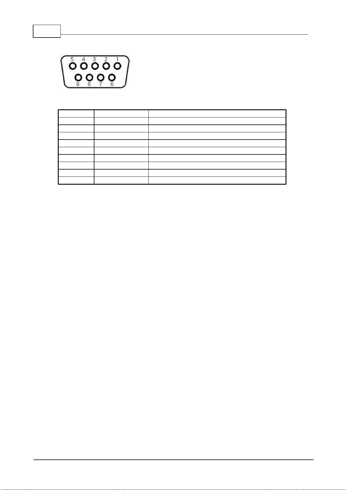
......................................................................................................................................................... 9Audio ......................................................................................................................................................... 10RS 232 ......................................................................................................................................................... 11GPIO Board
................................................................................................................................... 136 LCD Menu
................................................................................................................................... 147 Password
Section 2 Display Function 16
................................................................................................................................... 161 Station ID
................................................................................................................................... 162 Mpx Encoder
......................................................................................................................................................... 16Audio Levels
......................................................................................................................................................... 17Pre Enphasis, Audio Level and Clipper
......................................................................................................................................................... 17Pilot Level And Phase
................................................................................................................................... 173 RdsEncoder
......................................................................................................................................................... 17PS,PI, PTY Indications
......................................................................................................................................................... 18Radiotext Indications
................................................................................................................................... 184 Changeover
......................................................................................................................................................... 18Set Up main channel and back up
......................................................................................................................................................... 19Changeover Setting Mode
......................................................................................................................................................... 19Changeover Time Set
......................................................................................................................................................... 20RDS Substitution(override) and Tunnel RDS-MPX
......................................................................................................................................................... 20Dropouts Reconize
......................................................................................................................................................... 20PI Code Control
......................................................................................................................................................... 21SNR on MPX
......................................................................................................................................................... 21Threshold Levels
......................................................................................................................................................... 22MPX parameters Reading
......................................................................................................................................................... 22RDS Data Buffer
................................................................................................................................... 225 System
......................................................................................................................................................... 22GPIO Port Control
......................................................................................................................................................... 23Reading Parameters
......................................................................................................................................................... 23Modem Status and SMS alarms Activation
......................................................................................................................................................... 24IP Settings
......................................................................................................................................................... 24Functioning, Alarms and Warninngs
......................................................................................................................................................... 25Software Version
......................................................................................................................................................... 25Blocco password
.................................................................................................................................................. 26Cambio password, blocco sistema
.................................................................................................................................................. 26Recupero password