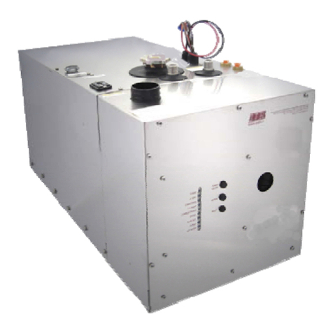
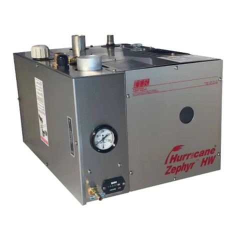
ITR Oasis Zephyr Oasis Zephyr HW User manual

Installation and
Operating Manual
Oasis®Zephyr™HW
Diesel Heating System for Recreational
Vehicles

Installation Manual for Oasis® Zephyr™HW Heating System
Manual Issue Date/Copyright © January 2021
International Thermal Research
IN CANADA: IN THE UNITED STATES:
2431 Simpson Road 5305 NE 121st Ave., Suite 401
Richmond, BC, Canada V6X 2R2 Vancouver, WA USA 98682
Tel: 1-800-755-1272 or 604-278-1272 Tel:1-800-993-4402 or 360-993-4877
Fax: 604-278-1274 Fax: 360-993-1105
Email: info@itrheat.com www.itrheat.com
Website: http://www.itrheat.com All rights reserved. No
part of this manual may be reproduced or transmitted in any
form by any means, electronic or mechanical, including
photocopying and recording, information storage, retrieval, or
transmission, without permission in writing from International
Thermal Research
Right to Modify:
Due to our commitment for quality and ongoing product
improvement, ITR reserves the right to modify or change
without notice, any materials, applications, equipment,
accessories, and/or prices. All measurements and weights are
approximate.
Read and save these instructions for future reference

International Thermal Research iii
Table of Contents
Technical Specifications and Standards
Dangers •Warnings •Cautions •Notices
Section 1, Overview....................................................................1-1
1.1 Unpacking the Heating System......................................... 1-1
1.2 Protect Your Warranty .................................................... 1-2
1.3 Heater Features............................................................. 1-3
1.4 Critical Factors .............................................................. 1-5
1.5 Equipment, Tools, and Skills ............................................ 1-5
1.6 Testing and Inspection.................................................... 1-6
Section 2, Mounting the Heater Unit............................................2-1
2.1 Before You Begin ........................................................... 2-1
2.2 Mounting Location.......................................................... 2-2
2.3 What NOT to Do ............................................................ 2-4
2.4 Procedure..................................................................... 2-4
2.5 Remote Operating Touch Screen Panel Mounting Procedure .. 2-5
Section 3, Installing the Exhaust System ....................................3-1
3.1 Before You Begin ........................................................... 3-1
3.2 Mounting Location and recommendations........................... 3-2
3.3 What NOT to Do ............................................................ 3-4
3.4 Procedure..................................................................... 3-4
Section 4, Installing the Fuel System ..........................................4-1
4.1 Before You Begin ........................................................... 4-1
4.2 Fuel System Installation and recommendations .................. 4-1
4.3 What NOT to Do ............................................................ 4-2
4.4 Procedure..................................................................... 4-3
Section 5, Installing Fan Heaters ................................................5-1
5.1 Before You Begin ........................................................... 5-1
5.2 Fan System Operation .................................................... 5-2
Features....................................................................... 5-2
Multiple-Zone Heating System ......................................... 5-2
Accessories and Components Needed................................ 5-3
5.3 What NOT to Do ............................................................ 5-3
5.4 Mounting Locations ........................................................ 5-4
5.5 Procedure..................................................................... 5-4

Table of Contents
iv Installation Manual for Oasis® Zephyr™HW Heating System
Section 6, Wiring the Electrical System....................................... 6-1
6.1 Before You Begin............................................................6-1
6.2 Oasis® Zephyr™12 VDC.................................................6-1
6.3 Oasis® Zephyr™120/240 VAC (Optional) ..........................6-2
Procedure .................................................................... 6.3
6.4 Electrical Components.....................................................6-4
6.5 What NOT to DO ............................................................6-6
6.6 Procedure .....................................................................6-6
6.7 Electrical Schematic........................................................6-9
Section 7, Plumbing and filling the System ................................. 7-1
7.1 Before You Begin............................................................7-1
7.2 Heat Transfer Fluid/Plumbing Installation Procedure............. 7-2
7.3 What NOT to Do............................................................. 7-4
7.4 Potable Water Plumbing Installation ..................................7-5
7.5 Engine Waste-heat and Engine pre-heat Plumbing ...............7-6
7.6 Procedure Filling/Purging the Heating System ..................... 7-7
Section 8, Hot Water Heating and Engine Heat Management ....... 8-1
8.1 Before You Begin............................................................8-1
8.2 Domestic Hot Water System ............................................8-1
8.3 Engine Waste Heat Function ............................................8-2
procedure .....................................................................8-3
8.4 Engine Pre-Heat Function ................................................8-3
procedure .....................................................................8-4
Section 9, Operating the Oasis Zepyhr heating System ............... 9-1
9.1 Features of the Oasis Zephyr Heating System .....................9-1
9.2 Starting the Heater.........................................................9-3
9.3 Signs of Normal Operation ............................................... 9-3
9.4 Main Control Board Operation...........................................9-4
9.5 Stopping the Heater (seasonal) ........................................9-4
9.6 Using the Electric Heating Elements .................................. 9-5
9.7 Activating the Cabin Fans through the Thermostats ............. 9.5
9.8 Activating the Domestic Hot Water....................................9-5
9.9 Domestic Water temperature Adjustment........................... 9-6
9.10 Stopping the Heater (Maintenance) ..................................9-7
9.11 Resetting a Fault ............................................................9-7
9.12 Electrical noise...............................................................9-7
9.13 Maitenance ...................................................................9-8
9.14 Protecting the Heating System ....................................... 9-10
Section 10, Troubleshooting..................................................... 10-1
10.1 Overview .................................................................... 10-1
10.2 Power On ................................................................... 10-1

Table of Contents
International Thermal Research v
10.3 Burner On ...................................................................10-1
10.4 Service Switch Off.........................................................10-2
10.5 Remote Switch Off ........................................................10-2
10.6 Heater Cycling .............................................................10-2
10.7 Thermostats Off............................................................10-3
10.8 Voltage Low of High ......................................................10-3
10.9 Overheat ....................................................................10-4
10.10 Fuse Blown ..................................................................10-4
10.11 Fuel Pump/Solenoid ......................................................10-5
10.10 Ignitor ........................................................................10-5
10.13 Combustion Fan ...........................................................10-6
10.14 Water Pump.................................................................10-6
10.15 Flame Out ...................................................................10-6
10.16 Compressor .................................................................10-8
10.17 Bypass Mode................................................................10-8
10.18 Water Pump On............................................................10-9
10-19 Flame Sensor Module ....................................................10-9
10.20 Test Points...................................................................10-9
10.21 Reduced Output..........................................................10-10
10.23 Smokey,Smelly Exhaust ..............................................10-10
10.24 A Silent Killer .............................................................10-11
Section 11, Maintenance...........................................................11-1
11.1 The First Few Weeks .....................................................11-1
11.2 Adding Coolant.............................................................11-1
11.3 Nozzle.........................................................................11-2
11.4 Fuel Lines and Filter ......................................................11-2
11.5 Combustion Chamber ...................................................11-2
11.6 Checking Hoses and Tubes .............................................11-2
11.7 Electrical System ..........................................................11-3
11.8 Recommended Spare Parts ............................................11-3
11.9 Protecting Hydronic Heating Systems ...............................11-4
Section 14, Warranty and Service .............................................14-1
14.1 Warranty.....................................................................14-1
14.2 Installations ................................................................14-2
14.3 Limited Warranty..........................................................14-3
14.4 Owner’s Responsibility ...................................................14-4
14.5 Not Covered Under Warranty ..........................................14-5
14.6 Customer Service Calls .................................................14-6
14.7 Returns .......................................................................14-7
14.8 Telephone Service.........................................................14-8
Inspection Check sheet (including Test Points)
Warranty Information & Warranty Card

Table of Contents
vi Installation Manual for Oasis® Zephyr™HW Heating System
List of Figures
Figure 1-1 Oasis® Zephyr™HW Heating System ...........................1-1
Figure 1-2 Oasis® Zephyr™HW Heating System Overview.............. 1-4
Figure 1-3 Oasis® Zephyr™HW Typical seiries-Plumbed Layout.......1-7
Figure 2-1 Oasis® Zephyr™HW Dimensions .................................2-3
Figure 2-2 Heater Mounting bracket configuration .........................2-4
Figure 2-3 Touchscreen Operating Panel Mounting ........................ 2-5
Figure 3-1 Oasis Zephyr™HW Typical Exhaust configuration............ 3.5
Figure 3-2 Fresh-air intake Config. and Optional Air Intake Silencer .. 3-5
Figure 5-1 Wiring the Fan’s Aquastat............................................5-2
Figure 5-2 Mounting a Spacesaver Fan ......................................... 5-5
Figure 5-3 Installing a Relay for Additional Fan Amperage ............... 5-5
Figure 6-1 Sample Wiring Diagram for Electrical Elements ............... 6-3
Figure 6-2 Wiring for a Fan Speed Switch .....................................6-8
Figure 6-3 Wiring Diagram V2001................................................ 6-9
Figure 7-1 Oasis® Zephyr™HW Heating System Overview.............. 7-3
Figure 7-2 Plumbing Zephyr™for 3 Zones (opt. summer loop).........7-4
Figure 7-3 Three Approved Methods of Installing Heater Hose..........7-5
Figure 7-4 Potable Hot Water System Plumbing ............................. 7-6
Figure 7-5 Engine Heat / Pre-heat System Plumbing.......................7-7
Figure 7-6 Filling/Purging Oasis® Zephyr Heating System ............... 7-8
Figure 8-2 Single Loop System, three fans, optional summer loop ....8-2
Figure 9-1 Mixing Valve Location..................................................9-6
Figure 11-1Maintenance Schedule .............................................. 11-4

International Thermal Research 1-1
Overview
Thank you for purchasing the Oasis® Zephyr™HW diesel
hot water heating system.
This section describes features of the Oasis® Zephyr™HW
heater and explains what to do when you first receive your
heater. It also covers critical information you need to know
before beginning the installation, including how to protect
your warranty, and tools and equipment needed.
Figure 1-1: Oasis® Zephyr™HW Heating System
Section
1
Some of the figures
in this manual
represent a typical
installation, but
other configurations
or methods may be
acceptable. If in
doubt, contact ITR
for assistance.

Section 1, Overview
1-2 Installation Manual for Oasis® Zephyr™HW Heating System
1.1 Unpacking the Heating System
When you receive your Oasis® Zephyr™HW heater:
1 Unpack it carefully.
2 Check each component against the provided parts list to
ensure that you have everything and that all parts are
undamaged.
3 If you discover any missing or defective parts, call ITR
immediately.
4 If you are not installing the heater right away, secure all
components so none will be misplaced.
5 Before installing the heater, read the rest of this
Instruction and Operation Manual. It contains
critical information for a proper installation.
It’s important to follow the installation procedures in this
manual to ensure maximum performance of the heater and
that you and/or your customers enjoy a warm, comfortable
environment and plenty of hot water when needed.
1.2 Protect Your Warranty
This document reflects approved installation techniques,
methods, and materials, and applies only to ITR equipment.
The heater and supplied components are only guaranteed by
ITR if the entire system has been installed according to the
requirements and recommendations set forth in this manual.
Warranty coverage will not be extended to heaters and
system components (supplied by ITR) used in an improper
installation. Use of any unapproved materials, equipment, or
installation procedures will void the warranty for the entire
heating system. ITR does not accept liability for any damage
or loss of service resulting from unapproved installations
and/or modifications.
NOTICE

Section 1, Overview
International Thermal Research 1-3
1.3 Heater Features
The Oasis® Zephyr™HW is an advanced and efficient hydronic
heater with many advantages over older technology of
forced-air systems. The Zephyr™provides space heating
using a “heat-transfer fluid”pumped to remote mounted, fan
equipped, radiator-style heat-exchangers. The same “hot”
fluid is circulated through a highly efficient, internally
mounted, flat-plate heat-exchanger to provide a continuous
supply of domestic hot water. The heater runs on 12VDC
power, using a diesel-fired burner to maintain the
temperature of the heat transfer fluid. The Oasis® Zephyr™
HW heater can also use waste heat from the engine, using
the internal heat exchanger. The addition of an optional
secondary water pump will also allow pre-heating of the
engine.
Other features of the heating system include:
·1500 Watt, 120 VAC (North America) electric element for
a supplemental and backup heating source when the vehicle
is connected to a power source
·High-temperature stainless steel burner and water jacket
to prevent premature warping or burnout
·Internal circulation pump for heating loop and hot water
heat exchanger
·Insulated enclosure retains heat and minimizes noise
·Easy to install, field serviceable, with hookups and
connections easily accessible from the top of the heater
·Quiet operation and low power consumption
·Low-pressure fuel system with built-in fuel pump
·Fuel-efficient burner capable of burning a wide variety of
diesel-based fuels
·No smoke or smell from the exhaust
·Fan assisted; sealed combustion chamber is designed to
use outside air through a direct ventilation hook-up
·Simple, low amperage draw ignition
Return fuel line to eliminate air and prevent nuisance
shutdowns
Oasis® Zephyr™HW
ADVANTAGES
•Efficient
•Clean
•Quiet
•Compact
•Safe
•Rugged
•Reliable
•Economical

Section 1, Overview
1-4 Installation Manual for Oasis® Zephyr™HW Heating System
·Electronically-controlled system with:
oAutomatic safety shutdown
oManual reset overheat temperature sensor and a
thermal cutoff for overheat protection
oTactile, Touch screen control panel for operating
control and diagnostics with audible alarm
·Heating control for up to four separate space heating
zones, each with its own optional thermostat
·On demand, continuous domestic water heating without
the need for hot water storage
·Use of engine waste heat to provide system heating
·Engine heating (using an optional external pump)
Figure 1-2: Oasis® Zephyr™HW Heating System Overview

Section 1, Overview
International Thermal Research 1-5
1.4 Critical Factors
THE INSTALLATION SHALL BE IN ACCORDANCE WITH THE
REGULATIONS OF AUTHORITIES HAVING JURISDICTION
The key factors to keep in mind when planning and installing
the heater are:
·Location restrictions for the heater, electrical control box,
and exhaust outlet (to reduce noise, vibration, heat loss,
etc.)
·Length, routing, and sizing of the hot fluid lines, fuel
lines, air-inlet venting and tubing, exhaust piping, and wiring
·Outside air - direct, unrestricted air intake requires a
draw of outside air for combustion
·Ability to easily access and service the product, especially
fuel, plumbing, and electrical systems
·After installation, ability to purge water and fuel lines and
inspect/test entire system using the ITR-supplied Inspection
Check Sheet.
1.5 Equipment, Tools, and Skills
As the user and/or installer, you must be qualified and
authorized to do the installation, which requires mechanical
aptitude and electrical knowledge. Make sure you comply
with existing RVIA industry practices, using the highest and
most recent standards and codes. Good workmanship is
essential. Refer to Section 1 –Overview, sub-Section 1.2,
Protect Your Warranty.
You will need the following equipment and tools (not
supplied) to install the heating system. This does not include
optional equipment and accessories:
·Standard tools normally available in a well-equipped shop
·Approved fasteners (used with the supplied mounting
hardware) for securely mounting the heater.
·Steel (or stainless steel) 1½”ID exhaust piping no longer
than 12’with no bends (see Section 3 –Installing the
Exhaust System, for details when bends are present).
·2”combustion fan intake hose, though-hull adapter and
clamps
Please pay attention
to notices of
“Danger”“Warning”
“Caution”and
“Notice”in this
manual.

Section 1, Overview
1-6 Installation Manual for Oasis® Zephyr™HW Heating System
·Exhaust collar
·¼”ID approved fuel supply and return lines
·#10 sheet metal screws or wood screws for mounting
internal fans.
·Heater hose –enough to connect the Oasis Zephyr to the
interior fans. If engine heat is used, heater hose is
required to connect the heater to the engine block (see
Technical Specifications and Standards for details)
·Clamps to secure all heater hose and fuel hose
connections
·Overflow bottle (min. 2 quarts) with clear plastic 1/2”ID
hose; tank must be heavy-duty plastic, with a vented, screw-
down cap, and sturdy enough to mount firmly to a vertical
surface
·DC compatible thermostat(s) depending on the number of
zones for temperature regulation of each zone (up to 4)
·A self-priming pump for filling the system with heat
transfer fluid after installation
·Cabin fans or passive radiators for distributing heat to the
living spaces
refer to Figure 1-3, for a typical series plumbed layout using
the Oasis® Zephyr™HW heater.
1.6 Testing and Inspection
After all components have been properly installed according
to standard practices, RVIA standards and the
recommendations of this installation and Operating Manual,
the heating system should be test-operated and inspected
for leaks and proper function.
For your convenience, you can use the pullout Inspection
Check sheet in this manual. The check sheet is divided into
progressive sections, allowing each phase of the inspection
to be carried out systematically, and then signed off by
authorized persons.

Section 1, Overview
International Thermal Research 1-7
Figure 1-3: Oasis® Zephyr™HW Typical Series-Plumbed Layout

International Thermal Research 2-1
Mounting –Oasis®
Zephyr Heating
System
2.1 Before You Begin
Plan the location of the Oasis®Zephyr Heating System and all its
major components in advance to ensure the chosen locations are
compatible with installation requirements and within the technical
specifications.
Consider the following factors to help you decide exactly where
best to mount the Oasis®Zephyr Heating System:
·Heater weight when full
·Ventilation requirements
·Exhaust outlet location and maximum acceptable length,
including all 90-degree bends. Refer to section 3.2.
·Potential for vibration and jarring
·Fuel storage location
·Most efficient plumbing runs
·Safe and convenient access for maintenance
·Number and location of interior fans
·Location of other equipment to be installed or connected to
Oasis®Zephyr including: control box, heat exchangers,
overflow tank, batteries, etc.
Make sure you are familiar with Section 1, Overview of this
manual. If the system is not installed according to specifications
and with the correct equipment, your heater may not operate
properly, safety may be compromised, and your warranty may be
voided.
Section
2
WARNING

Section 2, Mounting the Heater Unit
2-2 Installation Manual for Oasis® Zephyr™HW Heating
2.2 Mounting Location
·Mounting location must be able to support double the gross
weight of the heater when full (i.e.70 lbs. x 2 = 140 lbs./63.5
KG) and must be of a non-combustible material.
·The Oasis®Zephyr™HW model is 10.5”H x 14”W x 19”D
(26.6 cm x 35.5 cm x 48.2 cm). See Figure 2-1: Dimensions
The Oasis® Zephyr™HW heater must not be installed in any
compartment with flammable gases.
·The Oasis® Zephyr™HW heater must be isolated completely
from all living spaces. Combustion air must be drawn directly
from an outside source and cannot contain any combustible
gases. Use the supplied air intake hose (part#8019) and the
aluminum air intake collar (part#10089). Securely clamp and
seal all air inlet hose connections. Ensure the supply of
combustion air to the appliance is not obstructed or cut off.
·The heater must be mounted in an area that provides
unrestricted access to the front panel, top access panel and
access to fuel, water, power and exhaust connections. There
should be at least 12”of clearance on the top of the heater for
accessing and servicing the components and water
temperature adjusting valve. Available space for connection to
the rear of the heater is necessary if vehicle engine heat
management is connected to the Zephyr. There should be at
least 1”clearance to all other Oasis® Zephyr™HW heater
surfaces.
·The heater must not be installed in any compartment with
flammable gases.
·The heater must be mounted horizontal and level using the
two included mounting brackets that bolt to the side of the
heater.
DANGER

Section 2, Mounting the Heater Unit
International Thermal Research 2-3
Figure 2-1: Oasis® Zephyr™HW Dimensions
If the Oasis® Zephyr™HW is going to be mounted in the engine
compartment, check for adequate ventilation. Make sure there
are no exhaust leaks and that all exhaust fittings are well-
fastened to the heater and the muffler. Any assembly parts that
may cause injury through accidental contact should be
protected. Isolate the unit in the closed compartment so that no
exhaust from the heater will infiltrate the living areas.
·Choose a sturdy surface in a location that won’t be unduly
affected by vibration and the jarring of rough roads.
·Mount the unit with the front panel facing out and accessible.
Facing out simplifies installation, maintenance and servicing.
There must be at least 12”of accessibility on top of the heater
for removal of the panel and servicing of the internal
components.
·Ensure that the exhaust tubing can be properly and safely
routed to the outside. The maximum exhaust run with 1 90-
degree bend is 12’. Any additional 90-degree bend will reduce
the allowable exhaust length by 2 feet.
WARNING

Section 2, Mounting the Heater Unit
2-4 Installation Manual for Oasis® Zephyr™HW Heating
2.3 What NOT TO DO
Don’tmount the heater without a direct connection to the
combustion fan from an outside air source.
Don’t mount the heater without the supplied exhaust fittings
installed and the exhaust directed out from under the vehicle.
Don’t mount the heater in a location that restricts access to the
service panels or creates interference with the top mounted
connections.
2.4 Procedure
After choosing the mounting location for the heater unit:
1. Mount the unit horizontally
2. Secure the heater in place (against the wall, floor or a
mounting platform) using the (2) supplied mounting brackets
that are bolted to the heater (using the existing bolts) on
each side of the bottom tray of the heater. The brackets are
fastened to the mounting surface using 1/4”through bolts or
wood screws with 1”diameter fender washers, lock washers
and nuts. (see fig. 2-2)
Figure 2-2: Heater Mounting Bracket Configuration

Section 2, Mounting the Heater Unit
International Thermal Research 2-5
2.5 Remote Operating Touch Screen
Panel Mounting Procedure
The Remote Operating Panel is mounted inside the Coach, in an
easy to access location. An opening for the remote panel must be
cut in the wall or mounting panel. The Remote Operating Panel
will be screwed in place using the 4 mounting holes.
Figure 2-3: Touchscreen Operating Panel Mounting

International Thermal Research 3-1
Installing the Exhaust System
3.1 Before You Begin
For efficient and safe operation of the Oasis® Zephyr™HW follow
all recommendations for properly installing the exhaust. Any
deviations from these recommendations must be approved in
advance by ITR.
Although the heater’s exhaust produces very low carbon monoxide
emissions, caution is advised:
·Do not operate the Oasis® Zephyr™HW in an enclosed area
unless there is adequate ventilation.
·Isolate the Oasis® Zephyr™HW in a closed compartment. Air
from this compartment must be allowed infiltrate any living
areas of the vehicle.
Heater exhaust can reach high temperatures; never install exhaust
parts close to combustible materials or through a combustible wall
or ceiling without fireproof protection. Heater exhaust must be
directed to the outside of the vehicle away from windows, inlet
vents, and slider-outs. The heater exhaust system must be installed
following all specific RVIA standards.
Section
3
!
DANGER

Section 3, Installing the Exhaust System
3-2 The Oasis® Zephyr™HW Installation Manual
3.2 Mounting Location
If all technical specifications for mounting the exhaust
cannot be met, don’t use the Oasis® Zephyr™HW. The
heater may perform poorly or be damaged if it is not
installed according to specifications.
Recommended Exhaust Outlet Locations
The following are recommended for exhaust outlet locations:
·Mount the exhaust outlet outside of the heater
compartment. Be aware that exhaust fumes could infiltrate
the vehicle if the exhaust is not vented correctly.
·In a typical vehicle installation the exhaust runs from the
bottom of the heater, through the floor and exits from either
side of the vehicle. Excluding the 90° bend from the heater
and without any additional 90° bends, the exhaust run cannot
exceed 12’. A 90° bend within the exhaust run reduces the
total allowable exhaust length by 2 feet. For example, if after
the 90° bend exiting the heater, the exhaust run includes one
90° bend, the total exhaust run cannot be longer than 10
feet.
·The outlet of the exhaust pipe must be located so the exhaust
exits directly out from under the vehicle and does not
accumulate under the vehicle. Exhaust outlets cannot be
located under an opening window, inlet vent or a slide-out.
Recommendations for Installation
·Combustion air must be drawn directly from outside the
vehicle using the supplied air intake hose. An (optional) air
intake silencer can be used (ITR part # 10455) see figure 3.1
·If an exhaust muffler is required, use an ITR-manufactured
muffler (part # 10282) with a straight-through design. No
other muffler is acceptable.
The exhaust and outlet are HOT and the surrounding areas
must be thermally shielded and protected from hot
surfaces and heat build-up. Nothing can come into contact
with any part of the exhaust system.
·Install an exhaust collar into the floor of the vehicle to isolate
the hot exhaust fittings, attached to the heater, from the
vehicle floor. (ITR part # 5164) Various exhaust collars are
available to accommodate different floor thicknesses.
!
DANGER
Table of contents
Other ITR Heating System manuals
Popular Heating System manuals by other brands

Envirovent
Envirovent heatSava user guide

Toyostove
Toyostove Laser 30 Installation and operation instruction

Aqua-Hot
Aqua-Hot 375-LP Service manual

Watts
Watts HKV Push'n'Go Series Installation and operating manual

Haier
Haier HACI-RP Series Instructions for installation, use and maintenance manual

Payne
Payne PY1P User's information manual

MSA
MSA AHS-1022 operating manual

BPC
BPC MVHR Series installation manual

Fresh-Aire UV
Fresh-Aire UV TUVC-ADS-118D-HO-OS-100 Installation & maintenance

Oxygen
Oxygen X-Air V200E Installation and operation manual

Midea
Midea CE-HRV-800 Owners manual and installation manual

Galletti
Galletti REKO 06 Installation - use - maintenance