ITT Industries FLYGHT 4610 Maintenance manual

Installation, care and maintenance
4610, 4620
893493/03

2
CONTENTS
This “Installation, Care and
Maintenance” applies to the following
versions of the 4600-series:
4610 4620
4610.410 4620.410
4610.490 4620.490
Notes for explosion approved ____ 3
Guarantee ____________________________ 3
Data plate interpretation ___________ 4
Product description ________________ 5
Applications _____________________________ 5
Motor data _______________________________ 5
Design __________________________________ 6
Materials _________________________________ 7
Weights __________________________________ 7
Transportation and storage_________ 8
Installation ____________________________ 8
Safety precautions _________________________ 8
Handling equipment ________________________ 9
Installation alternatives _____________________ 9
Page Page
Electrical connections _____________ 10
Operation ____________________________ 13
Before starting ___________________________ 13
During operation __________________________ 13
Care and maintenance _____________ 14
Safety precautions ________________________ 14
Service __________________________________ 14
Recommended inspections _________________ 15
Changing the oil __________________________ 17
Replacing the propeller ____________________ 17
Fault tracing (Troubleshooting) ___ 18
General Danger:
Non-observance given to safety
instructions in this manual, which
could cause danger to life have
been specifically highlighted with
this general danger symbol.
High Voltage:
The presence of a dangerous volt-
age is identified with this safety
symbol.
Non-observance to this warning
could damage the unit or affect its
function
WARNING!
Identification of safety and warning
symbols

3
Flygt guarantees that a spare parts stock will be kept
for 15 years after the manufacture of this product has
been discontinued.
The manufacturer reserves the right to alter perfor-
mance, specification or design without notice.
Official approval applies only providing:
—that the product is used under condition
described in the care and maintenance
instructions and in applications for which
it is intended;
—that the monitoring equipment incorporated
in the product is correctly connected;
—that all service and repair work is done by
a workshop authorized by Flygt;
—that genuine Flygt parts are used.
Flygt undertakes to remedy faults in products sold by
Flygt provided:
— that the fault is due to defects in design, materials
or workmanship;
— that the fault is reported to Flygt or Flygt’s repre-
sentative during the guarantee period;
— that the product is used only under conditions de-
scribed in the care and maintenance instructions
and in applications for which it is intended;
— that the monitoring equipment incorporated in the
product is correctly connected;
— that all service and repair work is done by a work-
shop authorized by Flygt;
— that genuine Flygt parts are used.
Hence, the guarantee does not cover faults caused by
deficient maintenance, improper installation, incorrect-
ly executed repair work or normal wear and tear.
Flygt assumes no liability for bodily injuries, material
damages or economic losses beyond what is stated
above.
GUARANTEE
The explosion proof version (Ex-approved) is de-
signed for use in explosive environments in accor-
dance with approvals stated on page 4.
Thermal contacts must always be
used on Ex-approved machine due
to approval conditions.
All work on the explosion-proof
motor section must be performed by
personnel authorized by Flygt.
Flygt disclaims all responsibility
for work done by untrained,
unauthorized personnel.
NOTES FOR EXPLOSION
APPROVED MACHINES
According to rules the Ex-approved
mixer must always work completely
submerged in the liquid.

4
DATA PLATE INTERPRETATION
APPROVAL PLATES
Always together with the general data plate.
EN: European Norm,
ATEX Directive
EN 50 014, EN 50 018, EN 1127-1,
ll 2 G EEx dll T4
GENERAL DATA PLATE A Serial number
B Product code + Number
C Curve code
D Country of origin
E Product number
F Additional information
G Phase; Type of current; Frequency
H Rated voltage
I Thermal protection
J Thermal class
K Rated shaft power
L International standard
M Degree of protection
N Rated current
O Rated speed
P Max. submergence
Q Direction of rotation: L=left, R=right
R Duty class
S Duty factor
T Product weight
U Locked rotor code letter
V Power factor
X Max. ambient temperature
A Approval
B Approval authority + Approval Number
C Approval for Class I,
D Approved drive unit
E Stall time
F Starting current/Rated current
G Duty class
H Duty factor
I Input power
J Rated speed
K Controller
L Additional information
M Max. ambient temperature
N Serial Number
O ATEX marking
D
A
N
K
L
M
CB
F
E
GIJ
H
O
M
LN
V
U
T
RS
Q
P
O
I
JK
H
G
F
E
D
BC
X
A
FM: Factory Mutual,
Class l Div. I Grp C and D
Class ll and III Div. I Grp E, F and G
Temperature class T4
Max. ambient temperature 40°C (105°F)

5
PRODUCT DESCRIPTION
Motor data
Data for liquid max 40°C (105°F)
4610
Applications
The mixer is intended to be used in:
— waste water treatment, anaerobic or oxygen satu-
rated water, presence of rags etc.
— industrial processes, heavy environments with high
demands of operational security, food and chemical
industry.
— industrial sewage processes, some wearing, pres-
ence of rags and metallic salt.
— mineral slurries with high wearing characteristics,
presence of rags acceptable.
— fish farms and current creating in dams, oxygen
supply, demands of environmental approved
materials. Sweet or brackish water.
The mixer is designed for use in many different situa-
tions where high flow capacity in relation to power
consumption is required such as solids suspension
and blending application.
The mixing effect is dependent upon the density and
the viscosity of the liquid and on the volume/shape of
the tank.
More than one mixer is required for larger tanks.
For other applications, contact your nearest Flygt
representative for information.
60 Hz, 0.9 kW (1.2 hp),
3 phase, 4 pole, 1685**r/min
Voltage Rated Starting
current current
VAA
200Y 3,5 16
200Y 4,0 21
220D 3.6 19
230Y 3,6 20
380Y 2,1 11
400Y 2,0 11
460Y 1,7 9
480Y 1,7 9,5
575Y 1,4 7,3
600Y 1,4 7,6
**) 460 V
50 Hz, 0.75 kW,
3 phase, 4 pole, 1385* r/min
Voltage Rated Starting
current current
VAA
200Y 3,5 16
230D 3,0 14
380Y 1,8 7,7
400Y 1,7 8,1
415Y 1,7 8,4
440Y 1,6 7,3
500Y 1,4 6,5
690Y 1,0 4,4
*) 400 V
50 Hz, 1,5 kW,
3 phase, 4 pole, 1390* r/min
Voltage Rated Starting
current current
VAA
200Y 7,2 28
230D 6,3 24
380Y 3,7 13
400Y 3,6 14
415Y 3,7 15
440Y 3,3 13
500Y 2,9 11
690Y 2,1 8,2
*) 400 V
60 Hz, 1,7 kW, (2,3 hp)
3 phase, 4 pole, 1670** r/min
Voltage Rated Starting
current current
VAA
200Y 7,7 37
220D 7,1 34
230D 7,3 35
380Y 4,1 19
400Y 3,9 18
440Y 3,5 16
460Y 3,3 16
480Y 3,4 17
575Y 2,7 13
600Y 2,7 13
**) 460 V
4620
4620
50 Hz, 0,75 kW,
1 phase, 4 pole, 1435* r/min
Voltage Rated Starting
current current
VAA
115 9,8 46
200 5,7 29
230 4,9 23
60 Hz, 0,9 kW (1,2 hp),
1 phase, 4 pole, 1740**r/min
Voltage Rated Starting
current current
VAA
115 11 58
200 6,7 37
220 5,5 27
230 5,5 29
*) 200 V **) 200 V
Only Ex-approved machines may be
used in explosive or flammable
environments or for mixing flamma-
ble liquids.
General description
These care and maintenance instructions apply to
both the standard version and the explosion proof
version of the submersible Flygt mixers.
The explosion proof version (Ex-approved) is
designed for use in explosive environments in
accordance with the approvals, see page 4.
The pH of the liquid: 1—12.
Liquid temperature: max. 40°C (105°F).
Warm liquid version max. 90°C (195°F). This version
has model designation ending with -W.
Depth of immersion: max. 20 m (65 ft).
Note, Ex-approved machines are permitted for max
liquid temperature 40°C (105°F).

Design
1. Cable entry
The cable entry has a sleeve and a compressible
rubber bushing to seal off and to relieve the cable.
2. Junction box
The junction box is completely sealed off from the
surrounding liquid.
3. Monitoring equipment
The stator incorporates three thermal contacts con-
nected in series.
The thermal contacts open at 125°C (260°F).
The thermal contacts should be connected for liquid
temperatures up to 40°C (105°F).
NOTE! The thermal contacts must always be connect-
ed in Ex-approved mixer.
See also “Electrical connections” and separate in-
structions for starter equipment.
The mixer can be equipped with leakage detector,
FLS 30, for sensing water in the inspection compart-
ment.
4. Motor
Squirrel-cage 3-phase induction motor for 50 Hz or 60
Hz.
The motor is started by means of direct on-line start.
The motor can be run continuously or intermittently
with a maximum of 15 evenly spaced starts per hour.
The stator is insulated in accordance with class F
(155°C, 310°F). The motor is designed to supply its
rated output at ± 5 % variation of the rated voltage.
Without overheating the motor, ± 10 % variation of the
rated voltage can be accepted provided that the motor
does not run continuously at full load. The motor is
designed to operate with a voltage imbalance of up to
2 % between the phases.
5. Bearings
The shaft is carried in two prelubricated and enclosed
ball bearings.
The bearings are dimensioned for more than 100 000
(L 10 aa) hours of operation.
6. Shaft
The motor shaft is delivered with the rotor as an inte-
gral part.
The motor shaft is completely sealed and will not
come in contact with the liquid.
7. Inspection chamber
An inspection screw facilitates checking for leakage of
liquid into the space behind the plug-in seal.
8. Oil housing
The oil lubricates and cools the seals, and acts as an
additional barrier against penetrating liquid.
Pressure build-up within the seal housing is reduced
by means of a built-in air volume.
9. Shaft seals
The mixer has a plug-in seal, which combines an inner
and an outer seal into one, rigid unit.
10. Propeller
The propeller is two-bladed and the blades have a
large width and a thin profile.
Jet ring
The mixer can be operated with or without a jet ring.
The jet ring improves the efficiency.
NOTE. Operation without jet ring affects the
power consumption.
Jet ring with vortex protective shield
In order to avoid vortex, the machine can be equipped
with a jet ring with protective shield.
6
5
9
4
56
123
810
7

7
Materials
Denomination Material Flygt No EN ASTM
Propeller, Jet ring, Stainless 0344. 1.4432 316L
Support, Lifting steel 2343.02
device:
Propeller1) Stainless
steel
Hi-Chrome
Shaft: Stainless 0344. 1.4057 431
steel 2321.03
Seal housing, Vinylester 0544. — —
Entrance cover: SMC CR30 9585.70
O-rings, Nitrile 0516. — —
Cable entry, rubber (NBR) 2637.04
Seal and rubber 70°IRH (black)
sleeve:
O-rings, Gasket, Fluorinated- 0516. — —
Cable entry, rubber (FPM) 2677.32
Seal and rubber 70°IRH (green)
sleeve:
Shaft seals:
Inner seals Outer seals O-rings
WCCR/WCCR RSiC/RSiC FPM
AL2O3/WCCR WCCR/WCCR FPM
AL2O3/CSb AL2O3/WCCR NBR
Corrosion resistant cemented carbide (WCCR)
Aluminium oxid (AL2O3)
Silicon carbide (RSiC)
Carbon (CSb)
1) only 4620 3-phase
Weights
Weight of mixer without motor cable is:
Min. kg (lb)
4610 11,5 (24,2)
4620 12,8 (26,5)
Max*. kg (lb)
4610 15,5 (35,3)
4620 17,0 (37,5)
*Incl. Jetring, vortex protection shield and guide claw unit

8
TRANSPORTATION AND STORAGE
WARNING! Always lift the machine by the lifting
device, never by the motor cable.
For a longer periods of storage, the mixer must be
protected against moisture and heat. The propeller
should be rotated by hand occasionally to prevent the
seals from sticking together. If the mixer is stored for
more than 6 months, this rotating is mandatory.
After a long period of storage, the mixer should be
inspected before it is put into operation. Pay special
attention to the seals and the cable entry.
To reduce the risk of electric shock,
see chapter “Installation”and
“Electrical connections”.
The tank of a sewage treatment plant
must be vented in accordance with
local plumbing codes.
The machine is not to be installed in
locations classified as hazardous in
accordance with the national electric
code, ANSI7NFPA 70-1990.
CAUTION!
This machine is intended to run fully
submerged. Level sensing equip-
ment should be installed if there is a
possibility that the machine could be
operated at less than the “minimum
submergence depth”.
INSTALLATION
Safety precautions
In order to minimize the risk of accidents in connection
with the service and installation work, the following
rules should be followed:
1. Never work alone. Use a lifting harness (part No.
84 33 02), a safety line (part No. 84 33 03) and a
respirator (part No. 84 33 01), as required. Do not
ignore the risk of drowning!
2. Make sure that there is sufficient oxygen and that
there are no poisonous gases present.
3. Check the explosion risk before welding or using
electric hand tools.
4. Do not ignore health hazards. Observe strict clean-
liness.
5. Bear in mind the risk of electrical accidents.
6 Make sure that the lifting equipment is in good
condition.
7. Provide a suitable barrier around the work area, for
example a guard rail.
8. Make sure that you have a clear path of retreat!
9. Use a safety helmet, safety goggles and protective
shoes/gloves.
10. All personnel who work with sewage systems
should be vaccinated against diseases that can
occur.
11. A first-aid kit must be available.
Follow all other health and safety rules and local
codes and practices.
In order to avoid accidents, warning
signs for rotating propellers and
machines that start automatically
must be positioned visibly. The area
in the proximinity of the machines
should be fenced off.
When mixing near a lake (jetties,
beaches and ponds etc.) a safety
distance of at least 20 meters (65 ft)
between the person and the ma-
chine is necessary. The machine
must never be placed directly in a
swimming pool. If used in connec-
tion with swimming pools, special
safety regulations apply.
Make sure that the mixer can’t roll or
fall over and injure people or damage
property.
Ex version!
Installation of the explosion-proof
mixer must be performed by autho-
rized personnel.
For some installations, and at cer-
tain operating points on the perfor-
mance curve, the noise level 70 dB
or the noise level specified for the
actual machine can be exceeded.

9
± 20°
± 60°
± 90°
± 30°
45°-180°
Installation alternatives
Flygt supplies equipment for the below methods of
installation which permit mixing over the horizontal
and the vertical plane.
NOTE!
If the mixer is operated without a jet ring, there
must be a stop function on the guide bar
to avoid the propeller from being swung
into the wall during operation.
Don´t position the mixer when it is operating.
All welded joints must be pickled and polished
before they come into contact with the liquid.
Handling equipment
Lifting equipment will facilitate handling of the mixer.
Normally the mixer can easily be installed without any
special lifting equipment.
WARNING! Always lift the machine by the lifting
device, never by the motor cable.
Keep out from suspended loads.
Make sure that the machine can't roll
or fall over and injure people
or damage property.
Avoid installations where:
— there are obstacles in front of the mixer,
— the flow on the suction side of the mixer is obstruct-
ed due to the design of the tank,
— the propeller can suck down air - vortex,
— directly over bottom diffusers.
To avoid vortex use a vortex protective shield or place
the mixer deeper in the liquid.
This is an absolute requirement for continuously oper-
ating mixers.
The mixer can be mounted on fixed structures, pillars,
stands, gratings, an anchored raft etc.
When installing, keep in mind the reaction force of the
mixer, which can be up to, for: 4610 260 N
4620 420 N
Run the cables so that they do not have any sharp
bends and are not pinched.
NOTE! The end of the cable may not be submerged.
Leads must be above flood level, as water may pene-
trate through the cable into the junction box or the
motor.
Consult your nearest Flygt representative regarding:
— choice of peripheral equipment.
— other problems in connection with installation.
In all installations, make sure that
the motor cable cannot be drawn
into the propeller.
Treat the cable as fragile, beware
that no sharp bends occure during
installation procedures, especially at
the entrance flange.
The “Cantilever system”
The “Single guide bar system”
The “Bottom fixing bracket system”

10
ELECTRICAL CONNECTIONS
All electrical work must be carried out under the super-
vision of an authorized electrician.
Local codes and regulations must be observed.
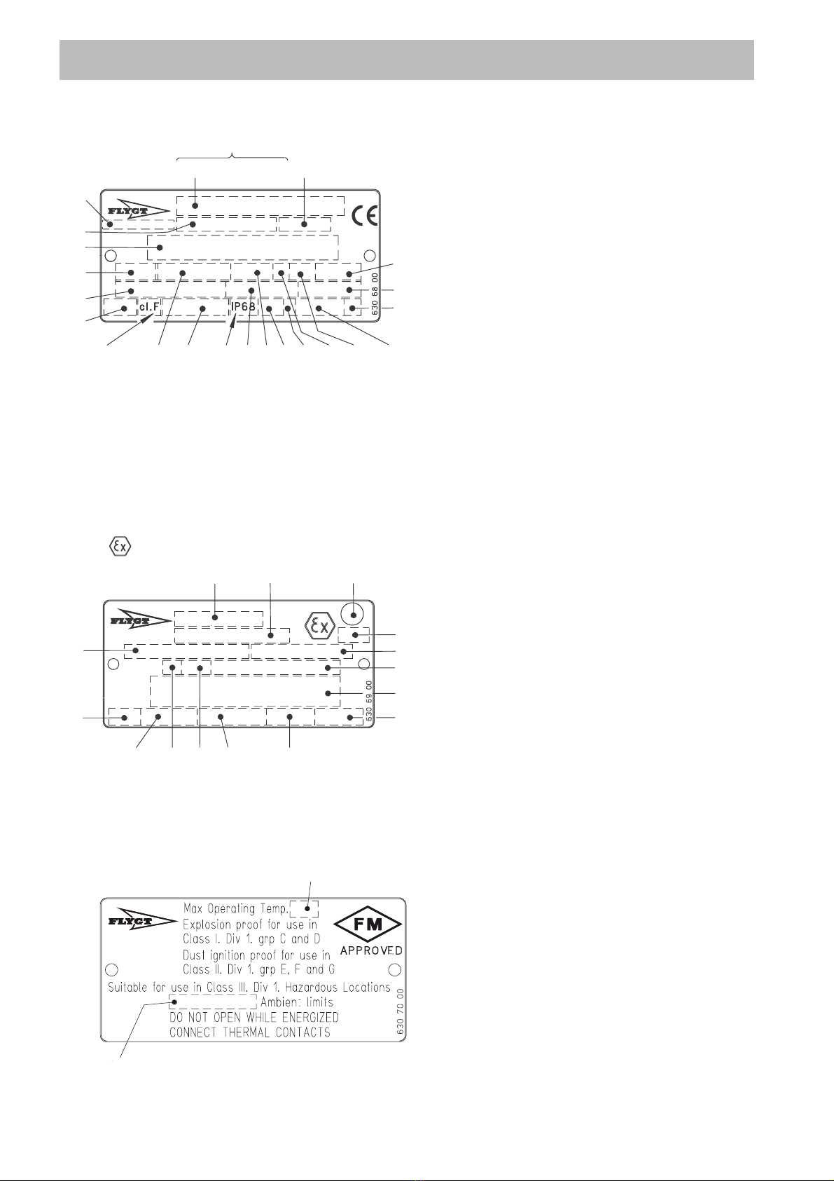
Check that the voltage and frequency on the data
plate agree with your actual power supply.
The motor can´t be connected for different voltages.
If intermittent operation is prescribed (see data plate),
the mixer should be provided with control equipment
that provides such operation.
To avoid leakage into the mixer check:
— that the cable entry seal sleeve and washers con-
form to the outside diameter of the cable. See the
parts list.
— that the outer sheath on the cable is not damaged.
When refitting a cable which has been used before,
always cut off a short piece of the cable so that the
cable entry sleeve does not compress the cable at
the same point again.
Remember that the starting surge can be up to 3.5
times higher than the rated current. Make sure that the
fuses or circuit breakers are of the proper amperage.
The table (see “Product Description”) gives rated cur-
rent and starting current. Fuse amperage and cable
must be selected in accordance with local rules and
regulations.
The overload protection (motor protection breaker)
shall be set to the motor’s rated current as given on
the data plate. With a clockwise phase sequence
L1-L2-L3 (R-S-T), the propeller will rotate correctly,
i.e. clockwise as viewed from the motor side. Check
the phase sequence in the main (line) using a phase
sequence indicator.
Three thermal contacts are incorporated in the stator
and are normally closed. The thermal contacts can be
connected to maximum of 250 volts, breaking at 4
amps. current at maximum.
Connect the thermal contacts to the starter.
Motor cable
CAUTION!
If the machine is intended for use with a
Variable Frequency Drive (VFD), be careful in
choosing a motor cable. The VFD might require
a screened cable.
Please, read the manufacturer’s instruction for
the VFD.
If necessary, contact your ITT Flygt represen-
tative.
Available motor cable are SUBCAB®,SUBCAB®AWG
or a chemically resistant cable e.g. HCR.
Connect the motor cable to the terminal board as
illustrated in the figure “Direct on-line start”.
Connect the leads from the motor control circuit to T1
and T2.
Tighten the screws so that the cable entry unit forms
an effective seal.
Connect the motor cable to the starter equipment.
Check the direction of rotation, see “Before starting”.
If the direction of rotation is wrong, transpose two of
the phase leads, only for 3 phase.
For 1 phase mixers rotating in wrong direction, please
contact your nearest Flygt reprensative.
NOTE! With long cables, the voltage drop must
be taken into consideration, since the motor’s
rated voltage is the voltage measured at the
terminal board in the machine.
NOTE! For safety reasons, the earth
lead should be longer than the phase
leads. If the motor cable is jerked
loose by mistake, the earth lead
should be the last to come loose
from its terminal. This applies to
both ends of the cable.
Make sure that the mixer is
correctly earthed (grounded).
WARNING!
If persons are likely to come into
physical contact with the machine or
mixed media (liquid) the earthed
(grounded) socket must have an
additional earth-(ground-)fault
protection device (GFI) connected.
Ex version!
Electrical connection of the explo-
sion-proof mixer must be performed
by authorized personnel.
Before starting work on the machine,
make sure that the machine is
insulated from the power supply
and cannot be energized.
Flygt disclaims all responsibility for
work done by untrained, unautho-
rized personnel.
Thermal contacts must always be
used on Ex-approved machine due
to approval conditions.

11
GC
W2
3 phase
6 lead stator, Y
V1 U2
V2
T1 T2
U1 W1
L2L1 L3 T1 T2
GC
3 phase
6 lead stator, D
T1 T2
U1 V1 W1
W2 U2 V2
L2
L1 L3 T1 T2
T1 T2
GC
T1 T2
Z1
U1
Z2 U2
1 phase,
4 lead stator
L3 L2
L1
Cable connection
The motor cable is connected to the stator leads with
closed end splices according to the figures.
Leads not in use must be isolated
All electrical equipment must be
earthed (grounded). This concerns
the machine as well as any control or
monitoring equipment. It is an ex-
treme danger to life not to follow the
above warning. Ensure that the
ground connection is actually
completed back to ground by
testing the ground circuit.
Cable
Cable leads Connection
colour starter
SUBCAB®4x1.5+2x1,5 mm
brown L1
blue L2
black L3
yellow/green earth
black T1 T1*
black T2 T2*
HCR SO7E6E5-71)
black 1 L1
black 2 L2
black 3 L3
black 4 T1*
black 5 T2*
black 6 –
yellow/green earth
Stator
Stator leads colour
3 phase
U1 Red
V1 Brown
W1 Yellow
U2 Green
V2 Blue
W2 Black
T1* White
T2* White
* Terminal for connection of thermal switches in motor and
monitoring equipment.
** GC = Ground Check
1) Not applicable for Ex
Cable leads Connect.
colour starter
SUBCAB®14AWG/7
red L1
white L2
black L3
yellow GC**
yellow/green earth
orange T1*
blue T2*
1 phase
U1 Red
U2 Brown
Z1 Yellow
Z2 Black
T1* White
T2* White

12
Monitoring equipment
Make sure that the monitoring
equipment incorporated in the
product is correctly connected.
Leakage detectors FLS
The FLS sensor consists of a small float switch for
sensing water in the junction casing and stator casing.
The FLS sensor is installed in the bottom of the junc-
tion casing.
The signal is fully compatible with MiniCas.
MINI
C
A
S
Blå/Blue Vit/White Vit/White
Blå/Blue Blå/Blue
alt Grå/Grey
alt Grå/Grey
Blå/Blue
FLS
Max 12 V
550 22 00
+T1
-T2
NOTE! In order to function properly the mixer
can be positioned up to ± 30°vertical angle.
NOTE! FM approved mixers must be provided
with FLS due the approval.

13
Watch out for the propeller and for the
starting jerk, which can be powerful.
OPERATION
During operation
Watch out for the propeller in rotation.
The mixer is intended to operate with or without a jet
ring, according to its main application area. Operating
without jet ring means that strict care must be ob-
served at test starting and in operation.
Test-run the mixer and note the current surge during
start-up. At the instant of starting, it is normal for the
current to exceed the operating current by 10—20 %
for a few seconds. The steady-state current should be
less than the rated current.
Excessive current consumption may be caused by
high viscosity or density of the liquid or an improperly
adjusted mixer.
Check that the mixer does not vibrate. Vibration can
occur when mixing is too vigorous in a small tank
volume, or when the inflow or outflow of liquid is im-
paired, by damaged and unbalanced propellers or by
air sucked down by the propeller.
Vibration can also occur due to interference between
several mixers.
For another operating direction for the mixer, contact
Flygt.
In continuous operation, air must not be drawn down
by the propeller (a vortex may not form).
NOTE!
In order to avoid overheating the machine,
it must alvays work comletely surmerged in
the liquid.
Check the direction of rotation. See the figure. The
propeller should rotate clockwise, as viewed from the
motor side.
The machine shall be fixed to the guide bar during
test.
Before starting
Check the seal casing, the mixer is not allowed to
work without liquid/a dry seal casing.
Remove the fuses or open the circuit breaker and
check that the propeller can be rotated by hand.
Check that the cable entry is securely tightened.
Check that the monitoring equipment (if any) works.

14
CARE AND MAINTENANCE
Safety precautions
Before starting work on the machine,
make sure that the machine is isolat-
ed from the power supply and can-
not be energized.
This applies to the control circuit as
well.
To prevent injury watch out for damaged and worn
parts.
NOTE! This applies to the control circuit as well.
The following points are important in connection with
work on the machine:
—make sure that the machine has been thoroughly
cleaned.
—observe good personal hygiene.
—beware of risk of infection.
—follow local safety regulations.
The mixer is designed for use in liquids which can be
hazardous to health. In order to prevent injury to the
eyes and skin, observe the following points when
working on the machine:
—always wear goggles and rubber gloves.
—rinse the mixer thoroughly with clean water before
starting work.
—rinse the components in water after disassembly.
—hold a rag over the seal housing screw when re-
moving it. Otherwise, pressure that may have built
up in the mixer due to leakage of liquid into the mix-
er may cause splatter into the eyes or onto the skin.
Proceed as follows if you get hazardous chemicals
in your eyes:
—rinse immediately in running water for 15 minutes.
Hold your eyelids apart with your fingers.
—contact an eye doctor.
on your skin:
—remove contaminated clothes.
—wash skin with soap and water.
—seek medical attention if required.
Make sure that the machine (or parts
of the machine) can't roll or fall over
and injure people or damage proper-
ty.
In some installations, the machine
surface and the surrounding liquid
may be hot. Bear in mind the risk of
burn injures.
Group Wear/Temperature Inspection Major
overhaul
Service
Major overhaul of the mixer should be made in a ser-
vice workshop.
Tendency to clog can easily be observed by means of
an ampere meter.
NOTE! Check the propeller. If the propeller is hard
worn and has a uneven leading edge, the motor can
be overloaded, because of clogging.
Inspection
Inspection involves that the following will be checked
and measured if required;
—replacement of all worn components.
—check all screw connections.
—check quantity and condition of the oil.
—check if there is liquid in the inspection chamber.
—check the cable entry and condition of the cable.
—functional check of the start equipment.
—functional check of monitoring equipment.
—check of direction of rotation.
—check the lifting device and guide bars (clearance
and wear).
—check of electrical insulation.
—replace all O-rings which were removed for inspec-
tion.
—check and rinse the space around the seals. See
also “Recommended inspection”
Inspections and service intervals
Regular inspection and preventive maintenance ensure
more reliable operation. The maintenance schedule
below gives the recommended period of time when the
machine should pass inspection and major overhaul.
The maintenance schedule is divided into two groups
A and B, depending on wear and temperature.
Ex version!
All work on the explosion-proof
motor section must be performed
by personnel authorized by Flygt.
Do not open the mixer when ener-
gized or in explosive gas atmosphere
A•None or moderate/ Every 8000 Once every
40°C (104°F) hours or five years
once a or every
year 50 000 hours
B•None or moderate/ Every 4000 Once every
40°C - 90°C hours or two years or
(104°F-194°F) twice a every 20 000
•Heavy 40°C (104°F) year hours or when
•Csb inner seal inspection
indicates.

15
Major overhaul
This requires special tools and should be done by an
authorized service shop. Workshop overhaul involves,
in addition to the inspection, the following:
—replacement of bearing.
—replacement of shaft seal.
—replacement of oil.
—replacement of O-rings.
—replacement of seals in cable entry and moving the
entry position of the cable.
—replacement of cable.
Service contract
Flygt or its agent normally offers service agreements
in accordance with a preventive maintenance plan. For
further information, please contact your Flygt repre-
sentative.
Recommended inspections
Inspection of Action
Visible parts on mixer Replace or fix worn and damaged parts.
and installation Make sure that all screws, bolts and nuts are tight.
Check the condition of lifting device/lifting eyes, chains and wires.
Check that the guide bar is vertical.
Replace worn parts if they impair function.
Oil quantity WARNING. If the seal leaks, the oil housing may be under
pressure. Hold a rag over the barroer fluid screw in order to prevent
splatter. See “Safety precautions”for additional information.
Check the oil housing, the mixer is not allowed to work without oil/a dry oil
housing.
Check the conditions of the oil in the oil housing, if the oil is much miscoloured or
mainly contains the ambient liquid, change the oil. Run the mixer 8000 h or one
year, check the oil, and if it contains too much from the ambient liquid again, the
fault may be;
—that the plug-in seal is defect. Contact a Flygt service shop
Inspection chamber Unscrew the inspection screw and check if there is liquid in the inspection casing.
If leakage has filled the inspection casing the fault may be:
—that the plug-in seal is damaged. Contact a Flygt service shop.
Oil drainage screwInspection screw

16
Inspection of Action
Cable entry Make sure that the cable entry is tight.
If the cable entry leaks:
—check that the entry is tightened and forms an effective seal.
—cut a piece of the cable off so that the seal sleeve seals onto a new
position on the cable.
—replace the seal sleeves.
—check that the gasket, seal sleeves and the washers, conform to the outside
diameter of the cable.
Cable Replace the cable if the outer sheath is damaged.
Make sure that the cables do not have any sharp bends and are not pinched.
Starter equipment If the starter equipment is faulty, contact an electrician.
Monitoring equipment Follow the instructions for monitoring equipment.
(should be checked often) Check:
—signals and tripping function.
—that relays, lamps, fuses and connections are intact.
Replace defective equipment.
Rotation direction of Transpose two phase leads if the propeller does not rotate clockwise as viewed
mixer (requires voltage) from the motor side. Rotation in the wrong direction reduces the capacity of the
mixer and the motor may be overloaded. Check the direction of rotation every time
the mixer is reconnected.
Insulation resistance Use an insulation tester. With a 1000 V-DC megger the insulation between the phases
in the stator and between any phase and earth (ground) should not be less than 1 MΩ.
Cable entry

17
Changing the oil
Oil drainage
Fill up with new oil in the oil filling hole, the mixer
should be in a vertical position. Always replace the
O-rings of the barrier fluid hole screws.
Put the screws back and tighten them. Tightening
torque 10 Nm (7.4 ft lb).
Recommended barrier fluid quantities for the mixers
4610 and 4620 is 15 centiliters.
Oil
We recommend that Mobil Whiterex or Shell Ondina,
with viscosity class ISO VG15 to 32, be used.
In media where paraffin oil is not required, a mineral
oil, i.e. compressor oil or hydraulic oil with (the same)
viscosity class VG15 to 32, should be used. Regular
motor oil, e.g. SAE 5(W) up to SAE 25(W) can also be
used.
The machine is delivered from factory with this type of
oil, a tasteless and odourless paraffin oil suitable for
raw or clean-water applications.
This oil is authorized according to FDA 172.878, (FDA
= Food and Drug Administration authority in US).
Unscrew the two oil screws.
Hold the mixer over a cup and allow the oil to run out.
The barrier fluid casing
may be under pressure.
Hold a rag over the
barrier fluid plug to
prevent splatter.
Oil refill
Replacing the propeller
Removing the propeller
Installing the propeller
Make sure that the end of the shaft is clean and free of
burrs. Polish off any flaws with fine emery cloth.
Grease the end of the shaft and the propeller hub.
Check that the seal ring is correctly positioned.
Lift the propeller onto the shaft.
Fit the washer onto the screw. Fit the unit and tighten.
Tightening torque 17 Nm.
Mount the protect cover.
Check that the propeller can be rotated by hand.
Remove the protective cover.
Insert an M8 Allen key into the hub screw and remove
the propeller screw.
Lift off the propeller.
Worn propeller can have very sharp
edges.
Use protective gloves!
Oil filling hole
Oil drainage hole

18
No Check:
—that the main power switch is on.
—that there is control voltage to the starter equipment and that
its fuses are intact.
—that there is voltage in each phase of the supply line.
—that all fuses have continuity and are tight.
—that the overload protection is reset.
—that there is no break in the motor cable.
Replace
Yes Clean
Contact Flygt service shop.
Is the propeller stuck?
WARNING: Disconnect power
before checking the propeller
No
Is the installation receiving voltage?
Yes
1.The machine fails to start
Yes Check the cause:
—If the stator temperature is high, check that the propeller
rotates easily.
—If there is a fault in the thermal switches, contact a Flygt
service shop.
Check that the overload protection is reset.
Yes Fault in control equipment.
Check:
—that all connections are intact.
—relay and contactor coils.
—that the control switch “Man/Auto”makes contact in both
positions.
A universal instrument (VOM), a test lamp (continuity
tester) and a wiring diagram are required in order to
carry out fault tracing on the electrical equipment.
Fault tracing should be done with the power supply
disconnected and locked off, except for those checks
which cannot be performed without voltage.
Always make sure that there is no one near the
machine when the power supply is turned on.
Fault Tracing (Troubleshooting)
Is an alarm signal indicated
on the control panel?
No
Can the machine be started
manually?
No
Use the following checklist as an aid to fault tracing. It
is assumed that the mixer and installation have for-
merly functioned satisfactorily.
Electrical work should be performed by an authorized
electrician.
Follow local safety regulations and observe recom-
mended safety precautions.
Is the start capacitor defective?
Only for 1 phase motor.
No
Yes
Ex version!
All work on the explosion-proof
motor section must be performed
by personnel authorized by Flygt.

19
2.The machine starts but motor protection trips
Yes Adjust.
Yes Clean the propeller.
Check that correct propeller size is assembled.
If anything else is wrong, contact Flygt service shop.
No Check the fuses.
Notify an electrician.
Yes If applicable, check capacitors. Contact Flygt service shop.
No Contact Flygt service shop.
Yes Contact Flygt.
Change to a propeller with a lower pitch.
Change to a more suitable mixer.
Yes Replace the overload protection.
Contact Flygt service shop.
Is the motor protection set too low?
(Check with data plate)
No
Is the propeller difficult to
rotate by hand?
WARNING: Disconnect power
before checking the propeller
No
Is the installation receiving full
voltage on all three phases?
Yes
Are the phase currents uneven
or too high?
No
Is r/min according to data plate
and specification?
Yes
Is the density of the liquid too high?
No
Fault on overload protection?
No
3.The machine starts-stops-starts in rapid sequence
Yes Check:
—contactor connections.
—the voltage in the control circuit in relation to the rated
voltage on the coil.
Contact Flygt service shop.
Do not override the motor protection repeatedly if it has tripped.
Does the contactor’s self-holding
function break?
No

www.flygt.com
4610, 4620.01.03. Eng. 1.5M. 12.01 © ITT FLYGT AB Printed in Sweden KT 211391 893493
This manual suits for next models
4