ITT Industries Jabsco 37055 Series User manual

QUIET - FLUSH
ELECTRIC TOILET CONVERSION
FEATURES
•Very quiet flush cycle - like a household toilet
•Converts all Jabsco, Par manual toilets and early
electric toilets to the new Quiet-Flush System
•Also converts Groco HC, HE & HF; Raritan PH,
Cricket & Compact; Sealand (Mansfield) 750 to 752
series and all Wilcox Crittenden toilets
•Single button flush actuator - with dual function water
level control switch
•Can be plumbed to any pressurized water system
that can provide a 3-1/2 GPM (13.5 LPM) flow rate
•Water control solenoid valve with anti-siphon breaker
to prevent contamination of potable water supply
•
High capacity waste macerator and bowl discharge pump
SPECIFICATIONS
PORTS Inlet 3/4" Hose Barb
Outlet 1" Hose Barb
MOTOR Meet U.S.C.G. Regulation
& SWITCH 183.410 and ISO 8846 MARINE
for Ignition Protection.
WATER 1-2 Quarts (Litres) per Flush
CONSUMPTION
VARIATIONS AVAILABLE
MODEL NO. DESCRIPTION
37055-0092* Toilet Conversion, 12 Volt EMC
37055-0094* Toilet Conversion, 24 Volt EMC
*This model is Marked and complies with EN50081-1 for suppression of
electro-magnetic interference.
OPERATION
The Quiet-Flush Toilet Conversion provides both quiet
operation and user control of water levels in the toilet
bowl. A single large push button switch provides a simple
flush mode by activating both the rinse water supply and
the macerator discharge pump simultaneously. An
additional rocker switch offers independent control of the
rinse water supply and discharge pump separately so the
bowl water level can be easily raised or lowered by the
user. This provides a method of minimizing water use,
when desired, as well as a means of raising the water
level in the bowl when appropriate for user comfort.
It also allows for complete evacuation of the bowl water
while underway in rough sea conditions.
INSTALLATION
PLUMBING
The 37055 Series Quiet-Flush Toilet Conversion can be
plumbed to any pressurized water system that can provide
a minimum of 3-1/2 GPM (13.5 LPM). This may be a fresh
water system including the vessel’s potable water system
or a washdown system utilizing either fresh or salt water.
However, it must be connected to a pressurized system
that normally remains on at all times while the vessel is
in use.
Before beginning the conversion, close all seacocks
connected with the toilet's plumbing system and take
precaution to ensure they remain closed until the
conversion is complete. If the toilet being converted is an
electric toilet, disconnect the electrical power to the toilet
and take precaution to ensure it is not restored until the
conversion is complete.
Disconnect both inlet and discharge hoses from the old toilet
and remove the toilet from its mounting surface. Remove
the hose connected to the back of the toilet's china bowl
and remove the china bowl and seat & lid assembly from
the old toilet base assembly. Ensure the bottom surface of
the china bowl is clean. The waste pump can be oriented
in any of the possible mounting positions that provides the
best clearance from surrounding obstructions but is gener-
ally best positioned so it points to the rear of the toilet
bowl.The four 6mm machine screws must be secured into
the base to form mounting studs to attach the china bowl.
Place one starlock washer on each of the phillips head
machine screws and a 6mm hex nut in each of the hex
shaped pockets on the top surface of the base. From the
underside of the base, screw one machine screw into each
of the nuts in the hex shaped pockets and tighten it to form
bowl mounting studs. Position the square section O-ring
Model 37055-Series
Model 37055-Series

in the O-ring groove on the top of the base and place the
china bowl on the base in the desired orientation relative to
the pump assembly. Place one plastic washer (to protect
the china), then one stainles steel washer on each machine
screw and attach the remaining hex nuts to secure the
bowl to the base. Cap each machine screw and nut with a
white decorative nut cap.
Position the toilet assembly in its intended installed position.
When locating the toilet, ensure there is adequate
clearance above and to the rear of the bowl so the seat
and lid assembly can rotate slightly past vertical and will
remain up when lifted. Once the exact position for the toilet
has been determined, mark the location of the three base
attachment holes on the toilet mounting surface.
Determine the best toilet attachment method using 1/4"
(6mm) fasteners (either machine screws for through
bolting or lag screws for topside atttachment) and drill the
appropriate size holes for the fasteners being used. If
securing the toilet with lag screws into a plywood
underlayment below fiberglass, be sure to drill a hole
through just the fiberglass layer large enough to allow
clearance for the screw threads and shank to avoid
cracking the fiberglass.
To make the water connection, shut off the water system
pump and open one of the systems faucets or fixtures to
drain the pressure from the system. Select an appropriate
tee type fitting that can be installed in the existing
pressurized water system and will provide a 1/2" (13mm)
hose barb to feed water to the toilet. Install the tee fitting at
a location on the pressurized water system that provides
convenient connection to the toilet’s solenoid valve/siphon
breaker assembly. If the toilet is being connected to the
vessel’s fresh water system and the vessel may be
connected to an unregulated city water supply, it is
recommended that a valve be installed in the toilet water
supply line ahead of the solenoid valve/siphon breaker to
regulate the flow rate of incoming pressurized city water.
The solenoid valve/siphon breaker should be positioned a
minimum of six inches above the hose connection at the
back of the toilet bowl (at all angles of heel and trim) and
located as close to the toilet as possible. It should be located
where an occasional drop or two of water from the siphon
breaker will not adversely affect nearby equipment or
supplies. It must be installed in a vertical position with the
hose barb connections pointing down. The solenoid
valve/siphon breaker bracket should be secured to a solid
mounting surface with four screws. If the valve assembly is
attached to a wood surface, 3/8" (10mm) long screws are
generally adequate to support the weight of the valve
assembly. If desired, the valve assembly may be installed
inside a cabinet or locker to conceal it from view of the
vessel’s occupants.To provide a clean sanitary appearance
inside the head area, a six foot section of smooth white
hose is provided with the toilet to connect the toilet bowl
spud fitting to the siphon breaker outlet hose barb.
The solenoid valve inlet hose barb is then connected with
1/2" (13mm) reinforced vinyl hose suitable for pressurized
water to the tee fitting installed in the water system line.All
pressurized water system connections should be secured
with stainless steel band type hose clamps. The 3/4"
hose connecting the siphon breaker to the bowl should be
secured with a band clamp at the siphon breaker to prevent
it from being accidentally dislodged but generally does not
need a hose clamp to secure it to the bowl spud fitting
unless desired for added security.
The discharge port includes a 1" (25mm) hose barb and
should be plumbed with 1" (25mm) hose to an on board
holding tank or, if appropriate, to an overboard discharge
through hull. A 1" (25mm) to 1-1/2" (38mm) barbed hose
adaptor is provided to adapt a 1" (25mm) discharge hose
to 1-1/2" (38mm) hose, if desired. The discharge plumbing
should be kept as short as possible and bends in the
discharge hose should be kept to a minimum. To retain
water in the bowl, the discharge hose should be looped
upward about eight to ten inches above the base of the
toilet and as near to the toilet as can be practically
accomplished without creating an unsightly plumbing
situation.
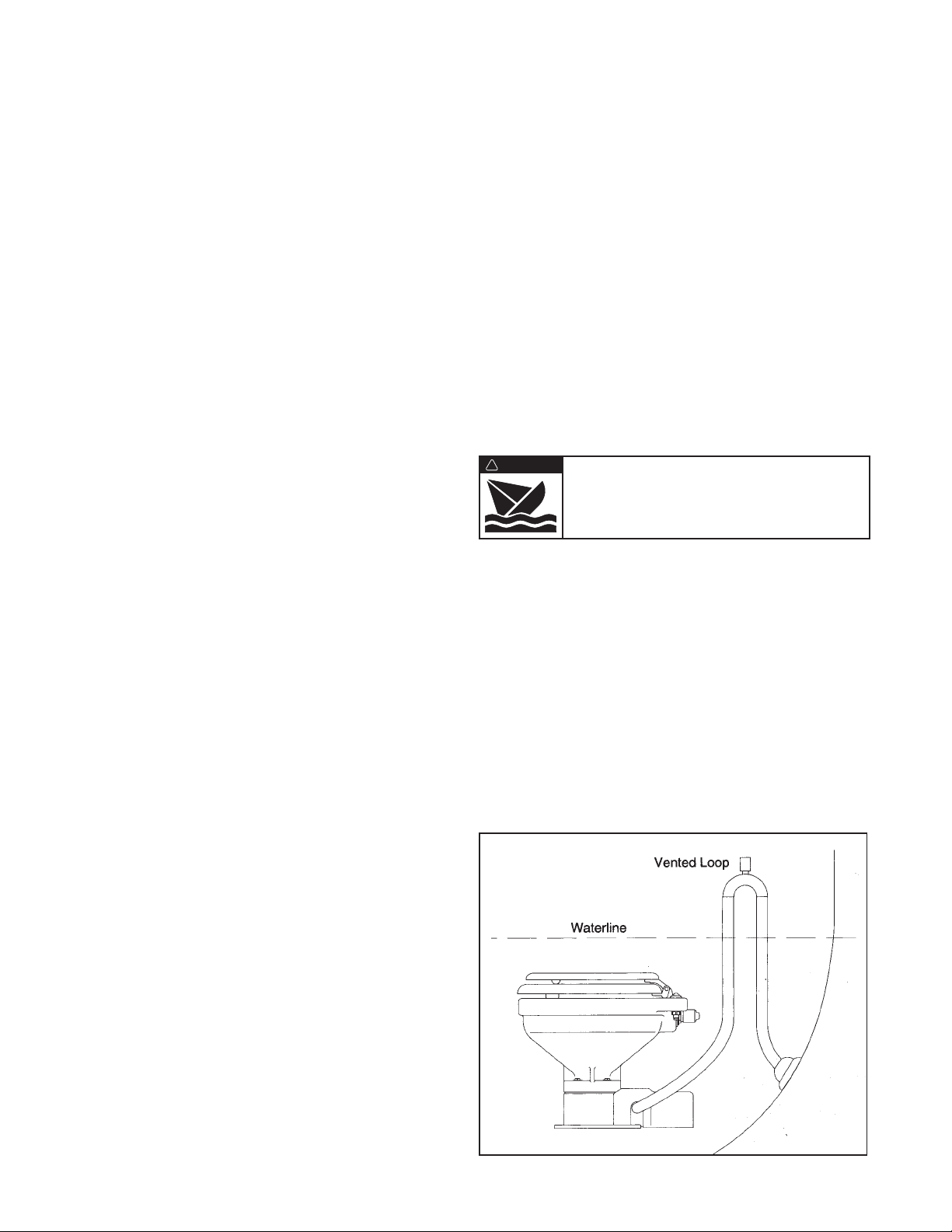
If the toilet is below the water line and is plumbed to an
overboard discharge through hull, the discharge plumbing
must include a vented loop positioned so it remains
above the water line at all angles of heel and trim. Total
discharge head should not exceed 4 feet (1.2M).
ELECTRICAL
The electrical wiring should be independent of all other
accessories. It should be made with marine grade copper
stranded wire of the gauge specified in the electrical
specifications chart. Make all wire connections with
mechanical locking type connectors (crimp type butt
connectors and terminals). Ensure the circuit is protected
by a proper sized fuse or circuit breaker determined from
Flood hazard. If toilet is installed below the
waterline, it must be installed with a properly
positioned vented loop in the discharge hose.
Failure to do so can result in flooding which
can cause loss of property and life.
WARNING
!

the electrical specifications chart. Secure all wires to a
solid surface approximately every eighteen inches (1/2M)
along their entire length of run.
Wire the switch panel to the solenoid valve/siphon breaker
and toilet pump assembly as per the following wiring
diagram. Connect the brown lead from the panel to the
waste pump positive (orange) lead. Connect the black
waste pump motor lead to battery negative. Connect the
yellow lead from the panel to a solenoid valve terminal.
Connect the remaining solenoid valve terminal to battery
negative. The solenoid valve is not polarity sensitive.
Select a location for the switch panel that is convenient
to the toilet user and will also allow access to run the
wires from the switch panel to both the toilet’s motor and
the solenoid valve/siphon breaker as well as from the
electrical power source to the switch panel. To install the
ELECTRICAL SPECIFICATIONS
Amp Fuse Wire Size Per Feet Of Run*
Voltage Draw Size 0'-10' 10'-15' 15'-25' 25'-40' 40'-60'
12 Vdc 10 25 #16 #14 #12 #10 #8
24 Vdc 5 15 #16 #16 #16 #14 #12
* Length of run is total distance from power source to product and back to ground.
RED
BROWN YELLOW
BROWN
YELLOW
RED
RED
RED
BROWN
YELLOW
To Waste Pump
Positive (Orange)
Motor Lead
To Solenoid
Valve/Siphon
Breaker
To Positive
WIRING DIAGRAM
switch panel, drill two 1-3/4" (45mm) diameter holes
(slightly over-lapping) through the selected switch
mounting surface per the attached template. Ensure the
template is oriented correctly because it is not
symmetrical. Also, drill four appropriate sized holes for
the fasteners selected to secure the switch panel to its
mounting surface.
SERVICE
The Jabsco Quiet-Flush Toilet does not require routine
maintenance other than occasional cleaning to maintain
a hygienic sanitary condition. Clean toilet with mild
nonabrasive cleaners without strong aromatics.
Cleaners having high concentrations of aromatics such
as pine scented concentrated cleaners and strongly
scented degreaser concentrates can cause the pump’s
seal to swell and may contribute to a premature seal leak.
UP
1-3/4" (45 mm) DIA
1-3/4" (45 mm) DIA
TEMPLATE

The toilet has no wearing parts that need periodic
replacement other than the shaft seal which, under
normal conditions, should provide several years of
service before needing replacement. The seal only
requires replacement if signs of leakage are noticed
under the seal housing positioned between the motor
and toilet base assembly.
Notice: Before performing any service, disconnect the
power supply to the toilet and take precaution to ensure
it is not reconnected until the service is complete. Also,
pump all water from the toilet bowl and if connected to
an overboard discharge, close the discharge seacock.
To replace the shaft seal, snap off the white motor cover
and remove the pump assembly by removing the four
screws with lock washers that secure it to the toilet base.
Carefully slide the pump assembly from the base
ensuring the macerator housing also slides out of the
base with the pump.
The pump chopper will engage the macerator housing and
it may be necessary to gently tap the chopper against the
macerator housing to free it from the base.
Prevent the motor shaft from turning by inserting a
screwdriver in the shaft slot at the rear of the motor and
unscrew the nut retaining the chopper blade. Remove
the chopper and macerator housing from the motor
shaft. Remove the O-ring from the O-ring groove around
the outer diameter of the seal housing. With an allen
wrench, loosen the centrifugal impeller set screw and
slide the impeller off the shaft. Remove the two screws
that secure the seal housing to the motor and slide the
housing off the motor shaft. Remove the two seal wash-
ers from under the head of each of the two seal housing
retainer screws. With a pair of needle nose pliers grasp
the shaft seal and pull it from the seal housing. Clean all
parts and inspect for damage.
Lubricate the OD of the new seal with a small amount of
water and press it into the seal bore with the seal’s lip
facing the threaded end of the shaft. Do not use the
stainless steel star retaining washer supplied with the seal.
Lubricate the ID of the seal and the motor shaft with a
small amount of water resistant grease. Ensure the slinger
is properly positioned on the motor shaft next to the motor
and slide the seal housing onto the motor shaft until it is
against the motor end bell. Position a new plastic seal
washer under the head of each of the flat head seal
housing retainer screws and secure the seal housing to the
motor. Slide the centrifugal impeller on the motor shaft
positioning it about 1/32" (1mm) from the seal housing and
secure it to the shaft with the set screw. Rotate the impeller
to ensure it does not rub on the seal housing.
Slide the macerator housing over the motor shaft, posi-
tion the SS chopper blade on the end of the shaft, then
place the nut on the shaft and tighten holding the shaft
slot at the rear of the motor. Position a new O-ring in the
seal housing O-ring groove (it may be retained in the
groove with a small amount of grease). Slide the pump
assembly into the toilet base ensuring the macerator
housing is properly positioned within the base. The cut-
out in the side of the macerator housing must align with
the discharge port in the base (the macerator housing is
keyed so it will only go in when properly positioned). En-
suring the O-ring is still properly positioned in the O-ring
groove in the seal housing, place the pump assembly
against the base and secure it in place with the four
screws and lock washers. Replace the white motor
cover by snapping it down over the pump motor.
Flood hazard. If toilet is plumbed to an
overboard discharge, close the discharge
seacock prior to disassembling toilet.
Failure to do so can result in flooding which
can cause loss of property and life.
WARNING
!

8
9
7B
10
11
14
12 13
20
4
15 16 17 18 19
21 22 23 24 25
26
13
2
7A
7B
7C
7D
7F
29
7E
5
6
FLUSH
FILLDRAIN
27 28
JABSCO
PARTS LIST Qty. Part
Key Description Req. Number
1Seat & Cover, Compact Size 1 18753-0437
Seat & Cover, Household Size 1 18753-0438
2Bowl, Compact Size 1 59127-7002
Bowl, Household Size 1 18753-0060
3 & 4 Bowl Spud & Intake Elbow 1 29048-0000
& O-ring
5Hose, 6 feet 1 29035-1031
6Motor Cover † 1 37044-6000
7Bowl Installation Hardware 1 18753-0637
7A Nut Cap** 4
7B Hex Nut** (Two places) 8
7C Washer, Stainless Steel** 4
7D Washer, Plastic** 4
7E Washer, Starlock** 4
7F Phillips Head Screw** 4
8Bowl O-Ring Seal 1 44101-1000
9Base Assembly** 1 37004-1000
10 1-1/2" Adaptor, Discharge Port 1 98023-0080
11 Joker Valve* ** 1 44106-1000
12 1" Discharge Port** 1 44107-1000
13 Screw** 3 96050-0568
14 Chopper Plate with Lock Nut † 1 37056-1000
15 Macerator Housing † 1 37014-0000
16 Centrifugal Impeller † 1 37006-0000
Qty. Part
Key Description Req. Number
17 Set Screw † 1 91084-0320
18 O-ring* † 1 43990-0066
19 Seal* † 1 1040-0000
20 Screw † 2 91010-0144
21 Washer, Plastic* † 2 35445-0000
22 Seal Housing † 1 37043-1000
23
Lock Washer #10, Stainless Steel †
4
24 Screw † 4 91027-0011
25 Slinger † 1 6342-0000
26 Motors:
Motor - 12 Volt EMC † 1 18753-0554
Motor - 24 Volt EMC † 1 18753-0555
27 Solenoid Valve & Siphon Breaker
12 Volt 1 37038-1012
28 Switch Panel 1 37047-1000
29 Screw Covers (3/kit) 1 37003-1000
Service Kit 90197-0000
Motor & Pump Assembly
12 Volt EMC 37072-0092
24 Volt EMC 37072-0094
*Parts Supplied with Service Kit.
** Parts included with base 37004-1000.
†Parts included in Motor & Pump Assembly.
EXPLODED VIEW

1 Dia
(25)
4
(102)
6 (152)
7-1/8 (181)
8-3/8 (213)
C Overall Width
B
FDE
5/16
(8)
3-1/8
(79)
A
9-7/8
(251)
13-1/4
(337)
3-3/4
(96) 6-1/8
(156)
2 Leads – 72 Long
(1830)
DIMENSIONAL DRAWING
Inches (Millimetres)
ABCDEF
Compact Size Bowl 2-7/8 (74) 14-1/8 (359) 13-1/8 (333) 16-1/2 (419) 10 (254) 6-1/2 (165)
Household Size Bowl 4-3/8 (112) 14-1/8 (359) 14-3/4 (375) 19-3/4 (502) 10-3/4 (273) 9 (229)
U.S.A.
Jabsco
Cape Ann Industrial Park
Gloucester, MA 01930
Tel: 978.281.0440
Fax: 978.283.2619
UNITED KINGDOM
Jabsco
Bingley Road, Hoddesdon
Hertfordsire EN11 OBU
Tel: +44 (0) 1992 450145
Fax: +44 (0) 1992 467132
CANADA
Fluid Products Canada
55 Royal Road
Guelph, Ontario N1H 1T1
Tel: (519) 821.1900
Fax: (519) 821.2569
JAPAN
NHK Jabsco Company Ltd.
3-21-10, Shin-Yokohama
Kohoku-Ku, Yokohama, 222
Tel: 045.475.8906
Fax: 045.475.8908
GERMANY
Jabsco GmbH
Oststrasse 28
22840 Norderstedt
Tel: +49-40-53 43 73 -0
Fax: +49-40-53 53 73 -11
THE PRODUCTS DESCRIBED HEREIN ARE
SUBJECT TO THE JABSCO ONE YEAR LIMITED
WARRANTY, WHICH IS AVAILABLE FOR YOUR
INSPECTION UPON REQUEST.
©Copyright 2003, ITT Industries Printed in U.S.A. All Rights Reserved Form: 43000-0663 Rev. 08/2003
This manual suits for next models
2
Table of contents
Other ITT Industries Toilet manuals
Popular Toilet manuals by other brands

Dometic
Dometic VacuFlush 4848 installation guide

SmartBidet
SmartBidet SB-2600 Quick installation guide

Dometic
Dometic SANIPOTTIE 960 Series instruction manual

Roca
Roca MULTICLEAN PREMIUM A80400800 manual

Woodbridge
Woodbridge B0940 installation instructions

LIXIL
LIXIL American Standard 760408-100.0070A installation instructions