Installation, Operation and Maintenance Instruction
Model ICB
ICB 100-english page 1
Revision 02
Article No 771076102
Issue 01/2010
TABLE of CONTENTS
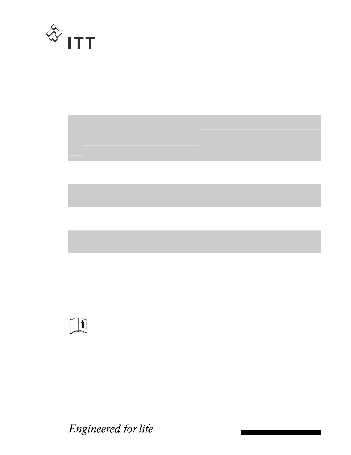
Pump Name Plate ..................................................... 2
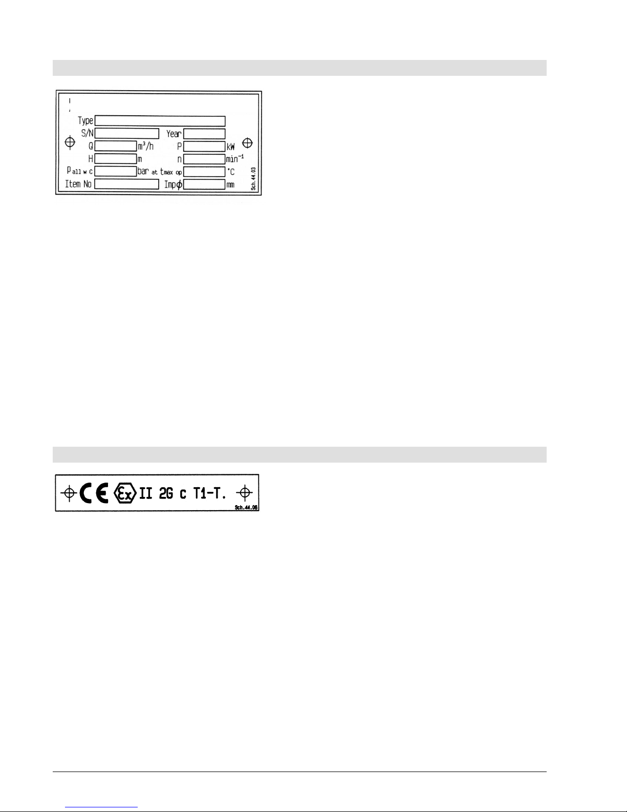
ATEX-Label (only for pumps in compliance with
EC directive 94/9/EG)................................................ 2
1. General................................................................... 3
1.1 Guarantee ......................................................... 3
2. Safety Regulations ............................................... 3
2.1 Marking of References in the Operating
Instructions.............................................................. 3
2.2 Dangers of non-observance of the Safety
Instructions.............................................................. 4
2.3 Safety Instructions for the Operator / Worker ... 4
2.4 Safety Instructions for Maintenance, Inspections
and Mounting Work ................................................. 4
2.5 Unauthorized Alteration and Spare Parts
Production ............................................................... 4
2.6 Undue Operation............................................... 4
2.7 Explosion Protection.......................................... 4
2.8 Use acc. to Regulations .................................... 6
3. Description ............................................................ 6
3.1 Design ............................................................... 6
3.1.1 Design Coding System................................... 6
3.2 Shaft Sealing ..................................................... 7
3.3 Bearing .............................................................. 7
3.4 Approximate Value for Sound Pressure Level .. 7
3.5 Permitted Nozzle Loads and Torques at the
Pump Nozzles ... ..................................................... 7
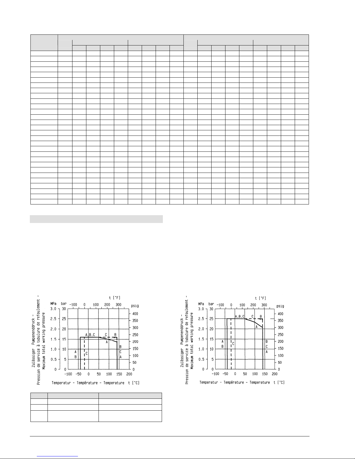
3.6 Permitted pressures and temperatures............. 8
3.7 Condensate ....................................................... 9
4. Transport, Handling, Storage .............................. 9
4.1 Transport, Handling........................................... 9
4.2 Storage / Conservation...................................... 9
5. Mounting / Installation ......................................... 9
5.1 Mounting of Pump / Unit.................................... 9
5.2 Connection of Pipings to the Pump................. 10
5.3 Drive................................................................ 10
5.4 Electric Connection ......................................... 10
5.5 Final Control .................................................... 11
6. Start-up, Operation, Shut down ........................ 11
6.1 Initial start-up................................................... 11
6.2 Switch on drive................................................ 11
6.3 Restarting ........................................................11
6.4 Limits of Operation ..........................................11
6.5 Lubrication .......................................................12
6.6 Monitoring ........................................................12
6.7 Shutting down ..................................................12
6.8 Storage / longer periods of non-operation .......12
7. Servicing, Maintenance ......................................13
7.1 General remarks..............................................13
7.2 Mechanical seals .............................................13
7.3 Motor bearings.................................................13
7.4 Cleaning of pump ............................................13
8. Dismantling and repair of pump ........................13
8.1 General remarks..............................................13
8.2 General............................................................13
8.3 Removal and Installation of screen in the motor
lantern....................................................................13
8.4 Removal of the Back Pull Out Assembly .........14
8.5 Removal of Impeller.........................................14
8.6 Removal of Shaft Sealing ................................14
8.7 Removal of Stub Shaft.....................................14
8.8 Reconditioning .................................................15
8.9 Mounting ..........................................................15
9. Spare parts, Spare pumps..................................16
9.1 Spare parts ......................................................16
9.2 Stand-by pumps...............................................16
10. Faults - Causes and Solutions.........................17
11. Motor Operating Instructions ..........................18
Installation Manual - Single mech. seal without shaft
sleeve (Design code S1..2) .......................................20
Installation Manual - Single mech. seal with quench
without shaft sleeve (Design code S4..2) ………...... 22
Sectional drawing pump unit (Design code S1..2),
Impeller with back vanes.......................................... 25
Sectional drawing pump unit (Design code S1..2),
Impeller with balancing holes ................................... 26
Sectional drawing pump unit (Design code S4..2),
Impeller with back vanes.......................................... 27
Sectional drawing pump unit (Design code S4..2),
Impeller with balancing holes ................................... 28
Connections ............................................................. 29
Dimensional drawing................................................ 30