ITW SIMCO ION IQ Power HL Sensor User manual

5201252 Rev. A
IQ Power HL Sensor
IQ Power™
HL Sensor
INSTALLATION AND OPERATING INSTRUCTIONS

i
IQ Power HL Sensor 5201252 Rev. A
TABLE OF CONTENTS
1. SAFETY WARNINGS............................................................................ 1
2. DESCRIPTION ................................................................................... 3
3. SPECIFICATIONS................................................................................ 4
4. INSTALLATION .................................................................................. 5
Unpacking.............................................................................................................................5
Mechanical Installation.........................................................................................................5
Intrinsic Safety Barriers........................................................................................................7
Sensor Interface ....................................................................................................................7
Electrical Connections..........................................................................................................8
Purge Gas............................................................................................................................10
Sensor Number ...................................................................................................................10
Set Up .................................................................................................................................11
5. OPERATION .....................................................................................13
6. MAINTENANCE .................................................................................14
Cleaning..............................................................................................................................14
Calibration ..........................................................................................................................14
7. TROUBLESHOOTING ..........................................................................15
8. PARTS & ACCESSORIES......................................................................16
9. WARRANTY & SERVICE ......................................................................17

1
IQ Power HL Sensor 5201252 Rev. A
1. SAFETY WARNINGS
Simco-Ion recommends that these instructions be read completely before installation or
operation is attempted. Failure to do so could result in personal injury and/or damage to
the equipment.
NOTE – Statements identified with NOTE indicate precautions necessary to
avoid potential equipment failure.
CAUTION – Statements identified with CAUTION indicate potential safety
hazards.
ATTENTION – Les déclarations identifiées avec ATTENTION indiquent des
dangers potentiels pour la sécurité.
WARNING – Statements identified with WARNING indicate potential serious
injury hazards.
AVERTISSEMENT – Les déclarations identifiées avec AVERTISSEMENT
indiquent un risque de blessures graves.
NOTE – This equipment must be correctly installed and properly maintained.
Adhere to the following notes for safe installation and operation:
1. Read instruction manual before installing or operating equipment.
2. Only qualified service personnel are to perform installation and repairs.
3. All equipment must be properly grounded, including machine frame to which the
equipment is mounted.
4. Disconnect input power before connecting or disconnecting any equipment.
NOTE – SENSITIVE ELECTRONICS: Risk of equipment damage.
• Donotelectricallydischargetosensorassembly.
• Sensormustbeconnectedtopowersupplyinpresenceofchargedmaterials.
NOTE – SENSITIVE ELECTRONICS: Risk of equipment damage.
• Avoidsharpblowstosensorassembly.
• Droppingsensormaycausedamagetosensors.
CAUTION – Installation must be in accordance with the National Electric Code
(NEC) or applicable government, state, providence or local regulations
ATTENTION – L’installation doit être en conformité avec le Code national
de l’électricité ( NEC ) ou le gouvernement applicable , l’état , la province ou
suivant les réglementations locales.

2
IQ Power HL Sensor 5201252 Rev. A
WARNING – Substitution of components may impair intrinsic safety. (Refer to
Control Drawing, Figure 3)
AVERTISSEMENT – La substitution de composants peut compromettre la
securite intrinseque. (Referez-vous au schema 3)
WARNING – Fire Hazard
To prevent ignition of flammable or combustible atmospheres, disconnect power
before servicing.
AVERTISSEMENT – Risque d’incendie
Pour éviter l’inflammation d’atmosphères inflammables ou combustibles ,
débrancher l’alimentation avant l’entretien.
WARNING – Sensor is not galvanically isolated, install according to NEC or
CEC as required by your local regulations.
AVERTISSEMENT – Le capteur n’est pas isolé , installer selon NEC ou CEC
tel que requis par les réglementations locales.

3
IQ Power HL Sensor 5201252 Rev. A
2. DESCRIPTION
The IQ Power HL Sensor is an electrostatic field measuring device packaged with a small
form-factor. This makes the sensor suitable for use in plastic film and web processing
applications. It can monitor processed materials for the presence, polarity and intensity
of electrostatic charges. This allows for detection of the undesirable condition of excess
static electricity and operation in CLFB (Closed Loop Feed Back) mode with additional
static neutralizing hardware.
The IQ Power HL Sensor is agency approved for mounting within hazardous locations:
Ex ia IIA T4 Ga
Class I, Division 1, Group D
TemperatureCodeT4,Ta=0˚Cto40˚C
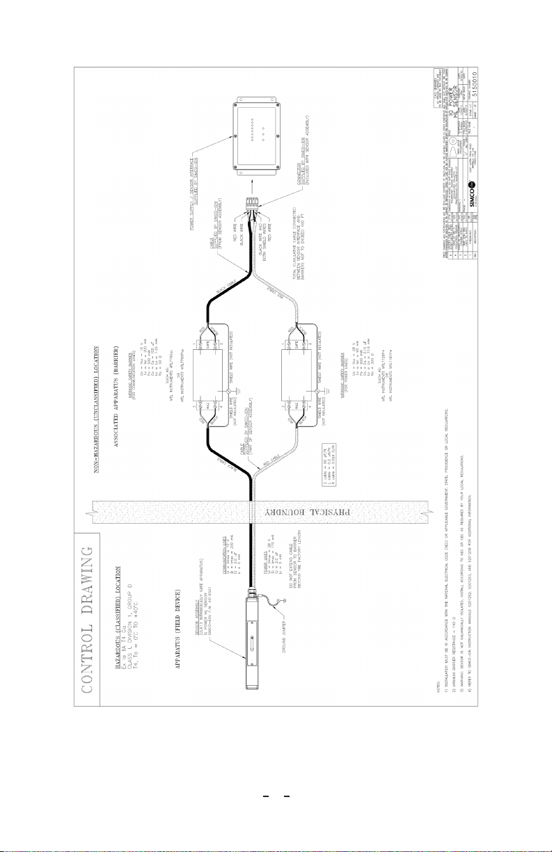
Each IQ Power HL Sensor must be connected to a pair of (user supplied) Intrinsic Safety
Barriers to maintain hazardous location approval. One of the Intrinsic Safety Barriers
provides protection for the circuit powering the sensor. The other Intrinsic Safety Barrier
provides protection for the digital communication circuit of the sensor. Barriers must be
compatible with device parameters as stated in Control Drawing 5150010.
The IQ Power HL Sensor interfaces with the IQ Power system through an IQ Power
Sensor Interface. The IQ Power Sensor Interface provides connection for up to eight (8)
IQ Power HL Sensors and connects to the IQ Power system through a convenient modular
cable. The interface also provides indicators for sensors connected and overall system
status. The IQ Power Sensor Interface and Intrinsic Safety Barriers must be located
outside the hazardous area, see Figure 3, Control Drawing 5150010.
The IQ Power HL Sensor may be integrated with an IQ Power system to provide closed
loop feedback (CLFB) control of static elimination. This provides for better neutralization
of static charges. Closed loop control will minimize troublesome under-compensation
and over-compensation often found in simple (open loop) static neutralizing applications.
Sensing charge on processed material also has the benefit of monitoring static neutralizer
performance. If static charge on processed material becomes excessive, it could be an
indication of service needed at the static neutralizing bar.
Static charge may not be readily apparent on processed materials. The IQ Power HL
Sensor makes the intangible tangible, by providing hard data about electrostatic charges on
processed materials. The sensor itself uses field sensing technology that provides accurate
and long term stability of static field measurement. A further benefit of this technology is
freedom from zero drift in the measurement.

4
IQ Power HL Sensor 5201252 Rev. A
3. SPECIFICATIONS
Input Power 24 VDC, 30 mA nominal
Input Connection via (user supplied) Intrinsic Safety Barriers (ref. Control Drawing
5150010)
Input Cable Lengths 30 ft (9.1m)
Input Purge Gas
(for minimizing dust, dirt and contamination in probe aperture
only)
1 to 2.5 psi (7 to 17 kPa) nominal operating pressure
5 psi (35 kPa) max operating pressure
0.14 scfm (4 NL/min) per sensor at 1 psi (5 kPA)
0.22 scfm (6 NL/min) per sensor at 2.5 psi (20 kPa)
Clean, dry, oil-free compressed air or nitrogen
Gas Input Connection ¼” OD Tubing, Quick Disconnect
Operating Temperature 40˚C [104˚F] max
Operating Humidity 70% RH max, no dewing permissible
Operating Distance*/Voltage
2” (50 mm) 20 kV max
3” (75 mm) 25 kV max
4” (100 mm) 30 kV max (factory default setting)
6” (150 mm) 40 kV max
8” (200 mm) 50 kV max
10” (250 mm) 60 kV max
Dimensions 260L x 32.5W x 44.5H mm [10.25”L x 1.28”H x 1.75”H]
Weight 0.68 kg [1.5 lb]
Enclosure Stainless Steel and Conductive Polyamide
Mounting Hardware Zinc plated metal perforated strip, stainless steel hardware
*Note: the operating distance set for sensor in control station must be the same as
mounting distance sensor to web. This is critical for accurate calibration.

5
IQ Power HL Sensor 5201252 Rev. A
4. INSTALLATION
Unpacking
Carefully remove all equipment from its carton and inspect contents:
• Checkthatdetailsonpackingslipcorrespondtodetailsofproductreceived.
• Checkthatequipmentisfreefromdamage.
• Ifanydamagehasoccurredduringshipment,notifylocalcarrieratonce.A
report should also be forwarded to Simco-Ion, 2257 North Penn Road, Hatfield,
PA 19440. See Section 9 of this manual for Return Shipment information.
Mechanical Installation
NOTE – Conductive machine parts or a static neutralizing bar in vicinity of static
sensor may have an undesired influence on its operation. For optimum results in
CLFB, static sensor must be installed as per Figure 2.
1. Downstream of static neutralizing bar, at a minimum distance of 12” (300 mm) from
static neutralizing bar so that any electric fields from static neutralizing bar will not
interfere with charge measurement.
NOTE – For CLFB applications, DO NOT mount sensor upstream of a static
neutralizing bar. Sensor must be mounted downstream of static neutralizing bar,
see Figure 2.
2. Install at an optimum distance from material to be measured. Mounting distance is
related to maximum static charge anticipated. The higher the anticipated charge, the
further the sensor should be mounted from material. If the input range of the sensor
is exceeded, the sensor will saturate and read the maximum. This does not cause
damage to the sensor. The factory default mounting distance of 4” (100 mm) will
provide an operating range of +/-30 kV.
Other operating distances and maximum operating ranges are:
•2”(50mm)20kV
•3”(75mm)25kV
•4”(100mm)30kV(factorydefaultsetting)
•6”(150mm)40kV
•8”(200mm)50kV
•10”(250mm)60kV
NOTE – Calibration of static sensor is distance dependent. If a distance other
than the factory default setting is used, the Mounting Distance setting will need to
be changed at IQ Power Control Station.
3. Sensors must face material to be measured and be perpendicular to surface.

6
IQ Power HL Sensor 5201252 Rev. A
4. DO NOT mount sensor over a roller or where material to be measured is in contact
with any other surface. Nearby metal reduces sensor readings by capturing electric
field lines.
NOTE – SENSITIVE ELECTRONICS: Risk of equipment damage.
Do not install sensor with charged materials present.
Sensor must already be connected to system in presence of charged materials.
NOTE – SENSITIVE ELECTRONICS: Risk of equipment damage.
Avoid sharp blows to sensor. Dropping sensor may cause damage to sensor
element.
Sensor should be mounted on a structure that is free of vibration.
Figure 1: IQ Power HL Sensor Mounting

7
IQ Power HL Sensor 5201252 Rev. A
Figure 2: IQ Power HL Sensor Positioning (downstream of neutralizing bar)
5. Attach sensor assembly using perforated mounting strip and hardware supplied. The
perforated strip may be bent or twisted prior to installation, if necessary. See Figures
1 and 2.
6. Secure perforated mounting strip to a machine frame or user supplied mounting
means.
7. Install ground jumper to ground stud and connect to machine frame ground.
8. Route sensor cable away from any moving machine parts and out of the hazardous
area. Secure cable to prevent damage.
Intrinsic Safety Barriers
Mount Intrinsic Safety Barriers (not included) between IQ Power HL Sensor and Sensor
Interface. The barriers must meet requirements in the Control Drawing 5150010. Barriers
must be mounted outside hazardous area and installed according to the manufacturer’s
instructions packaged with barrier. Note that two barriers (of different ratings) are
required for each sensor in the system.
Sensor Interface
Mount IQ Power Sensor Interface as per instructions included with unit. The interface
must be mounted outside the hazardous area. The interface provides power from and
communication with the IQ Power system (Control Station).

8
IQ Power HL Sensor 5201252 Rev. A
Electrical Connections
Figure 3 IQ Power HL Sensor Control Drawing 5150010

9
IQ Power HL Sensor 5201252 Rev. A
NOTE – Turn line voltage power off at IQ Power Control Station before
connecting / disconnecting any devices. This is to avoid potential equipment
failure and ensure proper digital communication.
1. Ground IQ Power HL Sensor by connecting ground lead between ground terminal on
end of sensor assembly and a good electrical machine ground.
2. Connect sensor to Intrinsic Safety Barriers. Cut sensor cable to length at barriers
allowing enough excess to make connections with barriers. NOTE: Best practice is
to shorten cable as much as practical to provide best possible digital signal integrity.
(DO NOT discard remaining cable as it will be used to connect barriers to Sensor
Interface).
Split twin cable from sensor approximately 6” (150 mm). Carefully remove 4”
(100mm) of jacket from each cable. Remove foil shield and trim off, using care not
to cut bare ground wire.
Strip red and black wires as required by barrier manufacturer for connection to
barrier. Connect each cable to the HAZ side of the appropriate barrier; see Figure 3,
Control Drawing 5150010. Note that one cable from sensor has a red jacket; this is
the cable that carries power to the sensor. The other cable, with a black jacket, carries
digital communications to and from the sensor.
3. Connect Intrinsic Safety Barriers to Sensor Interface using remnant of sensor cable
from above step.
Splittwincable approximately6”(150mm). Carefullyremove4”(100 mm)ofjacket
from each cable. Remove foil shield and trim off, using care not to cut bare ground wire.
Strip red and black wires as required by the barrier manufacturer for connection to the
barrier. Connect each cable to the SAFE side of the appropriate barrier; see Figure 3,
Control Drawing 5150010.
Split the twin cable approximately 4” (100mm). Carefully remove 2” (50 mm) of jacket
from each cable. Remove foil shield and trim off, using care not to cut bare ground wire.
Strip red and black wires ¼” (6-7 mm) and connect to Sensor Port terminal block on
Sensor Interface.
Figure 4 IQ Power HL Sensor Terminal Block Wiring

10
IQ Power HL Sensor 5201252 Rev. A
4. Connect Sensor Interface to IQ Power system (Control Station) using modular cable
according to instructions included with the interface.
Purge Gas
NOTE – Purge gas or compressed air used with this device MUST be clean and
dry. Dirt, water or oil in the purge gas will damage sensor. If the installation
location is prone to surface contamination (such as a coating line) the use of purge
gas is mandatory to maintain sensor operation.
In dirty or dusty environments low pressure purge gas may be used to prevent sensors from
becoming fouled with debris. The purge system is designed to provide a gentle flow of
purge gas at each sensor aperture where the electrostatic field is measured.
In environments with aerosol or vaporous contaminates (substances that tend to create
a film on surfaces) purge gas MUST be used. Purge gas prevents fouling of the sensor
element which will cause failure of the sensor.
The purge gas must be prepared with filtration and pressure regulation to ensure a low
pressure flow of clean, dry, oil-free air. Operation of the purge system calls for purge gas
at 1 to 2.5 psi (7 to 17 kPa). Connection to sensor bar is made with a ¼”outside diameter
tubing quick disconnect. Tubing must be clean and may include typically used tubing
materials such as nylon, polyethylene or polyurethane. To connect sensor assembly, make
sure tubing is cut cleanly and not at an angle, then simply push tubing into fitting on end
of bar.
NOTE – Do not apply more than 10 psi (70 kPa) to the purge gas fitting or
equipment damage may result.
Route tubing away from any moving machine parts and secure tubing to prevent damage.
Sensor Number
NOTE – Do not plug two or more sensors with the same Sensor Number into the
same Sensor Interface. Duplication of Sensor Numbers on an interface will cause
unstable operation and corruption of data.
Each IQ Power HL Sensor is assigned a Sensor Number. The sensor number may be 1
through 8. The IQ Power HL Sensor comes from the factory with a label on its cable
identifying its assigned Sensor Number.
The Sensor Number is used to identify the sensor and data associated with it. When the
sensor is connected to an IQ Power Sensor Interface, an indicator will illuminate next to
the corresponding Sensor Number. The Sensor Number will also appear on the Control
Station display to indicate data received from that specific sensor and adjustments that
may be made to that specific sensor.

11
IQ Power HL Sensor 5201252 Rev. A
In connecting sensors to a given IQ Power Sensor Interface, sensor numbers may NOT be
duplicated. Connecting multiple sensors with the same Sensor Number to an interface will
result in unstable operation and corruption of sensor reporting data.
Each sensor will light an indicator on the Sensor Interface that corresponds to its Sensor
Number. If the total number of indicators lit does not match the quantity of sensors
connected to the interface, check for a duplication of Sensor Numbers.
The Sensor Number is normally assigned at the factory and a label is applied to the cable
end indicating Sensor Number. The Sensor Number may be changed in the field, see
procedure 5201257.
Set Up
A variety of information can be checked and operating parameters set for the IQ Power
HL Sensor through the IQ Power Control Station via the Sensor tab. Tap on the device
icon for the sensor interface or neutralizer to access these pages. Then tap on sensor tab
for details about a particular sensor. To edit or select an operating parameter, tap on the
pencil icon to right of parameter description.
Device Name: A user editable name to identify specific Sensor Interface.
Sensor Quantity: The number of sensors connected to sensor interface.
Mounting Distance: A user entered dimension, the spacing between face of sensor and
web (surface being measured). The factory default mounting distance is 4” (100 mm).
NOTE – This information (Mounting Distance) MUST be correct. It is used by
sensor for calibration. If this information is not correct, sensor calibration will be
incorrect.
Average: The average web voltage of all sensors connected to interface. If the Sensor
Interface is paired with a static neutralizer, the average for CLFB (Closed Loop Feedback)
will also be displayed.
Sensors for CLFB: If Sensor Interface is paired with a static neutralizer, sensors selected
for CLFB will be displayed by their sensor number. The user selects these sensors.
Warning Setpoint: The web voltage level at which the sensor will set a “Warning”
and display an alarm icon on Control Station display. The factory default value is 5kV,
however this value may be user adjusted.
Fault Setpoint: The web voltage level at which the sensor will set an “Alarm” and display
an alarm icon on Control Station display. The factory default value is 20kV, however this
value may be user adjusted.
Web Voltage Sensor x: The web voltage from sensor “x”, where “x” is the sensor number.

12
IQ Power HL Sensor 5201252 Rev. A
Calibration Date Sensor x: The date sensor “x” was calibrated, where “x” is the sensor
number also reports firmware revision in sensor assembly circuit board.
Up Time: The amount of time that sensor interface has been up and running.
Device Address: The address of Sensor Interface, a number 1 thru 10, used by Control
Station to differentiate devices and also used to define association between devices.
Device Version: The firmware revision in interface circuit board.
Device Locator Utility: Causes indicator lights on the device (Sensor Interface) to flicker
for a brief time to aid in verifying location of a given device.
Alarm Test Utility: Causes an alarm output to aid in checking / troubleshooting alarm
sensing connections.
Closed Loop Feedback (CLFB) Mode: The IQ Power HL Sensor can be used as part of
a closed loop feedback system to control an IQ Power Static Bar. In this configuration the
ion output from the static bar is optimized to provide the best possible web neutralization.
If the IQ Power HL Sensor is connected to the system through a static neutralizing power
supply (HL or HLC & RDM), the sensor will automatically be paired with the neutralizer
and a sensor tab will appear on the page for the neutralizer. Pairing may also be achieved
manually by setting the setting the Sensor Interface Device Address to the same number
as the neutralizer address. Setting the Operation Mode to CLFB (closed loop feedback)
is performed on the Static Bar device page, under the Neutralizer tab. In this operating
mode, the static neutralizing bar MUST be upstream (before) the sensor.

13
IQ Power HL Sensor 5201252 Rev. A
5. OPERATION
NOTE – Before switching on power; ensure units are properly grounded and the
Sensor, Isolation Barriers & Sensor Interface are all properly installed.
Operation of sensor is controlled through the IQ Power Control Station. In operation, a
device icon appears on the IQ Power Control Station Home Page. Tapping on the device
icon for the sensor interface or neutralizer enters a page with a tab containing information
about each sensor. This includes descriptive information such as the device name and
firmware revision levels. User inputs such as the sensor mounting distance (critical for
correct calibration), warning and alarm set points, device name and add’l info. Output
information includes web voltage for each sensor. Warning and alarm outputs are also
included in these pages.

14
IQ Power HL Sensor 5201252 Rev. A
6. MAINTENANCE
WARNING – Fire Hazard
To prevent ignition of flammable or combustible atmospheres, disconnect power
before servicing.
AVERTISSEMENT - Risque d’incendie
Pour éviter l’inflammation d’atmosphères inflammables ou combustibles ,
débrancher l’alimentation avant l’entretien.
Cleaning
Clean sensor assembly using a lint-free wiper moistened (but not saturated) with isopropyl
alcohol. Use caution, and avoid contact with sensor aperture. Allow sensor to dry
completely before applying power.
Calibration
Sensors should be calibrated to ensure accurate measurement. Calibration is performed at
the factory or authorized service center. Recommended calibration interval is one year.

15
IQ Power HL Sensor 5201252 Rev. A
7. TROUBLESHOOTING
NOTE – Only qualified personnel are to perform troubleshooting tasks.
Problem Cause Solution
Power indicator
on interface NOT
illuminated
No supply voltage
from Control Station
Turn on Control Station
Change POWER & COMM
connection at Control Station
Wiring problem
between interface
and Control Station
Check wiring for cuts or breaks
Check connectors for
disconnection
Warning indicator on
interface illuminated
and a sensor number
indicator is blinking*
Interface is in
“Warning” (web
voltage above
Warning Setpoint)
Correct problem causing high web
voltage
Increase Warning Setpoint to
eliminate nuisance warning
Fault indicator on
interface illuminated
and a sensor number
indicator is blinking*
Interface is in
“Alarm” (web
voltage above Alarm
Setpoint)
Correct problem causing high web
voltage
Increase Alarm Setpoint to
eliminate nuisance alarms
Fault indicator on
interface flickering
(Comm indicator
illuminated)*
Internal fault in
interface
Cycle power to interface to see if
fault clears
Fault indicator and
a sensor number
indicator on interface
are flickering (Comm
indicator illuminated)*
Wiring problem
between sensor and
interface
Check sensor wiring for cuts or
breaks
Check connectors for
disconnection
Problem with sensor
module
Disconnect sensor and cycle power
to verify if sensor is the problem
Repair or replace defective sensor
Comm indicator
on interface NOT
illuminated
Wiring problem
between interface
and Control Station
Replace interface modular cable
with known good cable
Incorrect number of
Sensor indicators are
illuminated on interface
Ex: 3 sensors connected,
only 2 Sensors LEDs lit.
Duplicate sensor
numbers
Check sensor numbers for
duplication. See 5201257 for
changing sensor number
* If Warning or Alarm is activated, see Control Station and tap on Warning / Alarm icon for details.

16
IQ Power HL Sensor 5201252 Rev. A
8. PARTS & ACCESSORIES
Part Description Part Number
IQ Power HL Sensor 4016501
Perforated Mounting Strip 4750079
Connector Kit (Sensor to Interface) 5051864
Intrinsically Safe Barrier Kit 5051866
Red & Black Cable (for between Barrier and Interface ONLY) 4810324

17
IQ Power HL Sensor 5201252 Rev. A
9. WARRANTY & SERVICE
This product has been carefully tested at the factory and is warranted to be free from
any defects in materials or workmanship. Simco-Ion will, under this warranty, repair
or replace any equipment that proves, upon our examination, to have become defective
within one year from the date of purchase.
The equipment being returned under warranty should be shipped by the purchaser to
Simco-Ion, 2257 North Penn Road, Hatfield, PA 19440, transportation prepaid and insured
for its replacement cost. Prior to returning any goods for any reason, contact Simco-Ion
CustomerServiceat(215)822-6401for aReturnAuthorizationNumber.Thisnumber
must accompany all returned items.
This warranty does not apply when the equipment has been tampered with, misused,
improperly installed, altered, has received damage through abuse, carelessness, accident,
connected to improper line voltage, or has been serviced anyone other than an authorized
factory representative.
The warranty does not apply when Simco-Ion parts and equipment have been energized
by other than the appropriate Simco-Ion power supply or generator, or when a Simco-
Ion power supply or generator has been used to energize other than Simco-Ion parts
and equipment. Simco-Ion makes no warranty, expressed or implied, nor accepts any
obligation, liabilities, or responsibility in connection with the use of this product other than
the repair or replacement of parts stated herein.
Information in this publication supersedes that in all previous published material.
Specifications are subject to change without notice.

5201252 Rev. A
IQ Power HL Sensor
Simco-Ion
2257 North Penn Road
Hatfield, PA 19440
(215) 822-6401
(800) 203-3419
www.simco-ion.com
© 2016 Simco-Ion. Printed in the U.S.A.
Table of contents
Other ITW Accessories manuals
Popular Accessories manuals by other brands

Philips
Philips Norelco 7100 series user manual

Netatmo
Netatmo Smart Video Doorbell user guide

idronaut
idronaut Ocean Seven 303Plus Operator's manual

Vertiv
Vertiv GEIST SwitchAir SA1-02005 Quick installation guide

RayTek
RayTek RAYCMLTJM operating instructions

Hydac
Hydac CS 1000 Series Operating and maintenance instructions