INTRODUCTION
A Vortex A/C enclosure cooler is designed to use ltered
compressed air to cool industrial control cabinets without the
use of any refrigerants. Hot air in the cabinet is vented to the
surroundings through a built-in vent in the Vortex A/C. Noise
generated by the Vortex A/C is comparable to normal speech
levels. The Vortex A/C has a built-in mechanical thermostat that
requires no electricity. To operate, simply install on your enclosure
and connect the compressed air source.
COMPRESSED AIR SUPPLY
The compressed air supply must be ltered (5 micron maximum)
to remove water and dirt. A 5 micron lter is supplied for this
purpose (Vortec model 701S-24A or 701S-36A). If oil is present
in the compressed air supply, remove the oil using an optional
0.01 micron coalescing lter (Vortec model 701S-48 or 701S-54).
Filter recommendations are given in Table 1.
If an oil removal lter is necessary, install it downstream of
the 5 micron lter. Change the lter elements as needed (see
Maintenance).
The appropriate size of compressed air supply line should be
selected to ensure optimal performance of the Vortec product.
Please refer to Table 2 to determine what supply line size is
recommended for your application. Contact Vortec at 1-800-441-
7475 for further assistance.
INTERNAL CABINET PRESSURE
The Vortex A/C, when operating at 100 psig (6.9 bar), will maintain
the internal enclosure pressure at approximately 35” (889 mm)
of water column. When the Vortex A/C is not cooling (when the
thermostat senses acceptable temperatures), the Vortex A/C is
not pressuring the enclosure. If you desire a constant positive
internal enclosure pressure, even when the Vortex A/C is not
cooling, this may be accomplished by removing a set screw
that is adjacent to the mechanical thermostat on the bottom of
the unit. By removing this set screw with a 3/32” (2 mm) hex
key), a small amount of air (3 cfm or 85 lpm) will pressurize the
sealed enclosure to approximately 1.5” (38 mm) water column.
This “pressurization air” will run continuously, regardless of the
thermostat operation, until the set screw is re-installed.
MAINTENANCE
The only maintenance involved with the Vortex A/C is normal
element changes to the compressed air lter. The lter element
should be changed when there is a noticeable decrease in
performance or when pressure drop across the lter exceeds
5 psig (0.3 bar). The Vortex A/C has only one moving part (the
mechanical thermostat/valve) which is not serviceable in the
eld. Do not disturb the setting of the thermostat. Evidence of
tampering with the thermostat may void the warranty.
If it is suspected that the compressed air lter has not been
maintained after an extended period of operation, there may be
dirt in the Vortex A/C. If the Vortex A/C is not cooling sufficiently,
there may be debris in the “generator” of the unit. To check, pull
the 1/2” (13 mm) inside diameter vinyl tubing off the cold air
outlet of the Vortex A/C and unscrew (with a 1” (25 mm) open
end wrench) the cold air outlet. Remove the O-ring. Remove the
white nylon washer(s). Then remove the red (model 7615) or the
blue (model 7625) or the brown (model 7635) generator. Inspect
the six slots in the generator for dirt and clean if necessary. Clean
the cavity in the Vortex A/C that the generator was located in
if necessary. Reassemble in reverse order. Tighten the cold air
outlet to 100 inch-pounds (11 newton meters) torque. Be sure to
supply clean (ltered to 5 micron) and oil free compressed air to
the Vortex A/C.
INSTALLATION
To maintain the UL Type 12 rating, the Vortex A/C MUST be
installed in one of the following congurations on a UL Type 12
enclosure:
a. Top mounted in an upright and vertical orientation, on
a at horizontal surface (as shown)
b. Side mounted, on a at vertical surface of the
enclosure, with the compressed air inlet pointing
upward. When side mounted, rotate the aluminum
louvered outlet on the back of the Vortex A/C so the
louvers point downward to the oor.
1. Position the Vortex A/C on the top or side of your enclosure
so that there is sufficient clearance for the internal mechanical
thermostat and cold air outlet, and, so that the entire mounting
“footprint” of the Vortex A/C is supported by the enclosure. (A
4-3/4” wide x 3-3/8” deep (121 mm wide x 86 mm deep) area).
Position the unit so that the louvered outlet on the back of the
Vortex A/C is away from personnel, if possible. Also, position
so that no internal enclosure components obstruct air ow
around the mechanical thermostat.
2. Cut a 1-15/16” (49 mm) diameter hole (1-1/2” knockout size)
in the selected location on the enclosure. De-burr any sharp
edges around this hole.
3. Remove the 1-1/2” electrical locknut from the Vortex A/C.
Insert the threaded portion of the Vortex A/C into the 1-15/16”
(49 mm) hole in the enclosure. (Be careful not to damage the
mechanical thermostat during installation.)
4. From inside the enclosure, screw the electrical locknut onto
the threads of the Vortex A/C. Tighten the locknut securely
to compress the 1/8” (3 mm) thick sealing gasket that is
positioned between the enclosure and the Vortex A/C.
5. Determine a suitable location for the Cold Air Muffler inside the
enclosure that is close to the cold air outlet of the Vortex A/C.
(You will need a surface area of approximately 2” x 9” (50 mm
x 229 mm) to mount the muffler. The Muffler can be mounted
in any orientation, horizontal or vertical.) Using the supplied
Muffler Mounting Clamp (with double sided tape), attach this
Clamp at the desired location. Clean the mounting surfaces
so that the double sided tape bonds securely. If desired, this
Clamp can be permanently mounted to the enclosure using
the supplied mounting hardware. Two 5/32” (4 mm) diameter
holes positioned on 3/4” (19 mm) centers must be drilled to
mount the Muffler Clamp. Use the plastic snap rivets to secure
the Muffler Clamp to the panel.
6. Snap the Cold Air Muffler into the Mounting Clamp.
7. Cut a sufficient length of the 1/2” (13 mm) inside diameter
vinyl tubing from the supplied #701M-43 Cold Air Ducting Kit
to connect the cold air outlet of the Vortex A/C to one of the
hose barbs on the Cold Air Muffler. Attach this length of vinyl
tubing so that it is free of sharp bends and kinks. Direction of
cold air ow through the Muffler is not important.
8. Attach all (or a portion of) the remaining supplied vinyl tubing
of the #701M-43 Cold Air Ducting Kit to the opposite hose barb
connection on the Cold Air Muffler. Holes can be punched
or drilled into this 1/2” (13 mm) tubing to distribute the cold
air evenly inside your enclosure, or, the entire cold air output
can be directed to a heat sensitive component. If the end of
the 1/2” (13 mm) vinyl tubing is plugged, at least sixteen 1/8”
(3 mm) diameter holes should be punched into the tubing to
allow the cold air to escape. Use the nine self adhesive tubing
clips provided in the kit to mount the tubing.
9. Connect the compressed air lter (model 701S-24A or
701S-36A) to the compressed air inlet on the side of the
Vortex A/C with a length of 3/8” pipe. Install the compressed
air lter as close as possible to the Vortex A/C, in a location
where the temperature does not exceed 125oF (52oC). Allow
the lter to hang at the side of the enclosure as shown in
the installation drawing. Use a 13/16” (21 mm) wrench to hold
the air tting on the side of the Vortex A/C stationary while
tightening the pipe connections. Note the air ow direction
arrow on top of the lter.
10. Connect the compressed air supply to the inlet of the air lter.
See “Compressed Air Supply”.
OPERATION
Operate the Vortex A/C at 90 to 100 psig (6.2 to 6.9 bar)
compressed air pressure. Do not operate at pressures above 150
psig. (10.3 bar) Operation at pressures less than 90 psig (6.2
bar) and above 100 psig (6.9 bar) can affect the “on” and “off”
temperatures at which the unit cycles. The Vortex A/C will cycle
on and off to maintain temperatures between 80oto 90oF (27oto
32oC). The Vortex A/C will not work properly at pressures below
70 psig (4.8 bar).
CAUTION: The louvered outlet on the back of the Vortex A/C
becomes hot during operation and can remain hot for a period of
time after the unit has cycled off. Note warning label precaution,
and avoid direct contact with this area of the unit during or after
operation.
TROUBLESHOOTING
Insufficient cooling may be caused by the following:
1. Undersized compressed air line size.
2. Compressed air pressure at the product is too low.
3. Partial or complete blockage of internal compressed air paths,
due to dirt.
4. Water vapor in the compressed air supply.
5. Loose cold air outlet tting. This may occur if not tightened
properly after being disassembled for cleaning.
If trouble persists, please contact Vortec at 1-800-441-7475.
LIMITED WARRANTY
Vortex A/C compressed air enclosure cooling products
manufactured by ITW Air Management will be replaced or
repaired if found to be defective due to manufacture within ten
years from the date of invoice. Refer to our website www.vortec.
com for full warranty details and limitations. ITW Air Management
makes no specic warranty of merchantability or warrant of
tness for a particular purpose.
GENERAL SAFETY CONSIDERATIONS
1. Do not operate a Vortex A/C at compressed air pressures
above 150 psig (10.3 bar).
2. Do not operate a Vortex A/C at line temperatures above
110 oF (43oC).
3. Avoid direct contact with compressed air.
4. Do not direct compressed air at any person.
5. When using compressed air, wear safety glasses with
side shields.
WARNING: COMPRESSED AIR COULD CAUSE DEATH,
BLINDNESS OR INJURY.
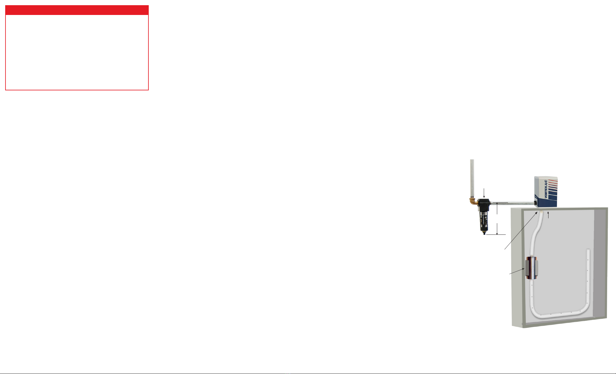
VORTEX A/C TYPE 12
(SHOWN TOP MOUNTED ON CUSTOMER’S ENCLOSURE)
Hole 1-15/16” (49 mm)
1-3/4” (44 mm) diameter
x 3-19/32” (91 mm) long
muffler and mounting
clamps
Vent Air
Filter
5-7/8”
(149 mm)