ITW VORTEC PANEL GUARD 701 Use and care manual

Please read all instructions BEFORE attempting to use this product
IMPORTANT
PANEL GUARDTM
UL TYPE 4
OPERATION & SAFETY
INSTRUCTIONS
Models 701, 701-15H, 701-35H, 770, 770-15H, 770-35H
(Includes all BSP versions of models listed above)
10125 Carver Road, Cincinnati, OH 45242
Phone: 513-891-7474 • Fax: 513-891-4092
Toll Free: 800-441-7475
www.vortec.com • techsupport@vortec.com

WARNING: COMPRESSED AIR COULD CAUSE DEATH, BLINDNESS
OR INJURY
1. Do not operate at compressed air pressures above 150 psig (10.3 Bar).
2. Do not operate at line temperatures above 110°F (43°C).
3. Avoid direct contact with compressed air.
4. Do not direct compressed air at any person.
5. When using compressed air, wear safety glasses with side shields.
Introduction
A Panel Guard is designed to use ltered compressed air to cool industrial control cabinets without the use of any
refrigerants. Hot air in the cabinet is vented to the surroundings through a built in relief valve in the Panel Guard.
The Panel Guard uses a xed mechanical thermostat (non-adjustable) to maintain cabinet temperature within the
desired range.
Compressed Air Supply
The compressed air supply must be ltered to remove water and dirt using a 5 micron or smaller lter. Failure
to use a lter may cause clogging (and freezing) of the compressed air paths inside the Vortec product. Filter
recommendations are given in Table 1.
Filter elements must be changed on a regular basis. Frequency of change is determined by the condition of the
compressed air supply. Filters should be installed in the compressed air supply line as close as possible to the
Vortec product.
The appropriate size of compressed air supply line should be selected to ensure optimal performance of the Vortec
product. Please refer to Table 2 to determine what supply line size is recommended for your application. Contact
Vortec at 1-800- 441-7475 for further assistance.
Installation
To maintain the Type 4 rating, the Panel Guard must be installed in a vertical orientation on a at horizontal surface
of a Type 4 rated enclosure (see Panel Guard Assembly).
Installation procedures:
1. Cut a 1-15/16” (1-1/2” knockout size) hole in the enclosure.
2. Insert Panel Guard into cut-out.
3. Tightly thread locknut onto the Panel Guard.
4. Perforate the ducting kit with several 1/8” holes and secure to interior of enclosure.
5. Attach the ducting kit to cold outlet of Panel Guard.
6. Connect compressed air lter to Panel Guard. Install the compressed air lter as close as possible to the Panel
Guard, in a location where the temperature does not exceed 125
°
F (52
°
C).
7. Connect compressed air supply to lter.
GENERAL SAFETY CONSIDERATIONS

Operation
Operate the Panel Guard at 90 to 100 psig (6.2 to 6.9 bar) compressed air pressure. Do not operate at pressures
above 150 psig (10.3 bar). Operation at pressures less than 90 psig (6.2 bar) and above 100 psig (6.9 bar) will
effect the operation. When properly sized for the application, the Panel Guard will maintain the internal enclosure
temperature between 75-100°F (24-38°C). Enclosure temperatures can momentarily reach 125°F (52°C) during
initial start-up and after long periods of inactivity. Variations in heat load and compressed air conditions can effect
thermostat operation. The mechanical thermostat will regulate an internal valve to minimize compressed air usage
and maintain enclosure temperatures within the range specied. In some applications, the Panel Guard may run
continuously at lower air usage with the benet of always keeping the enclosure under slight internal pressure. In
other applications, the Panel Guard may cycle on and off to maintain enclosure temperatures.
NOTICE: The thermostat’s reaction to temperature change depends on several factors: the internal and external
heat loads, enclosure size and proximity to the heat source. When the internal heat load is zero (or very low) and
when external temperatures are below 50°F (10°C), the thermostat will take longer to react to air temperature
increases. There will be a lag between the rising air temperature and when the thermostat reacts, which can result
in temperatures inside the enclosure exceeding 125°F (52°C). When air and thermostat temperatures equalize, the
reaction to temperature change is improved and the lag is minimized.
Maintenance
Panel Guards can be disassembled for cleaning. Do not remove or adjust the brass thermostat.
Unscrew the cold cap and remove the generator for cleaning.
Temperature ranges are calibrated at the factory and are non- adjustable.
Troubleshooting
Insucient airow or cooling may be caused by the following:
1. Undersized compressed air line size.
2. Compressed air pressure too low.
3. Partial or complete blockage of internal compressed air path, due to dirt.
Insucient cold air temperature may be caused by:
1. Compressed air line temperature too high.
2. Water vapor in the compressed air supply.
3. Loose cold cap. This may occur if not tightened properly after disassembled for cleaning.
If trouble persists, please contact Vortec at 1-800-441-7475.
Limited Warranty
Vortec compressed air products manufactured by ITW Air Management will be replaced or repaired if found to be
defective due to manufacture defect within ten years from the date of invoice. Refer to our website www.vortec.
com for full warranty details and limitations. ITW Air Management makes no specic warranty merchantability or
warrant of tness to a particular purpose.

Panel Guard Assembly
(Drawings shown below are not to scale)
Models 770, 770BSP, 770-15H, 770-15HBSP, 770-35H, 770-35HBSP
1-15/16"
Hole
1/4" NPT
(F)
Air Filter
Plug end of
tubing if holes
are punched in
length of tubing
(as shown)
Ducting Kit
Cold Air
Mechanical
Theremostat
Vent

LIT0152
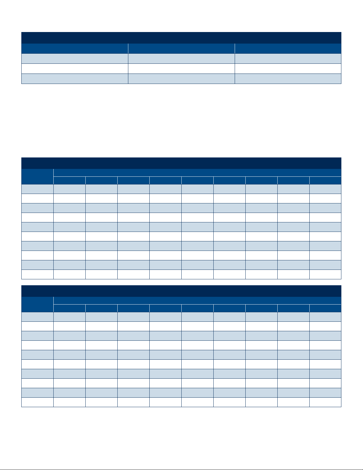
FILTER AND REPLACEMENT PART ITEM NUMBERS
Vortec Model Oil Removal Filter Replacement Generator Kits (5 pcs)
701, 770 701S-48 208GK-25H
701-15H, 770-15H 701S-48 208GK-15H
701-35H, 770-35H 701S-48 208GK-35H
Table 1: Filter Recommendations
Table 2: Determining Compressed Air Line Size
1. Calculate total product compressed air consumption (SCFM, SLPM).
2. Determine length of compressed air line required for connection to main supply.
3. Locate pipe length in left column and read to the right to nd the compressed air requirements.
4. Locate pipe size at top of column.
MAXIMUM AIRFLOW (SCFM) THROUGH PIPE AT 5 PSIG PRESSURE DROP (100 PSIG AND 70OF)
Pipe Length
(Feet)
Pipe Size (Nominal) - Schedule 40
1/4 3/8 1/2 3/4 1 1-1/4 1-1/2 2 2-1/2
10 29 65 120 254 480 978 1483 2863 4536
20 21 46 85 180 340 692 1049 2024 3208
30 17 37 70 147 277 565 856 1653 2619
40 15 32 60 127 240 489 792 1431 2268
50 13 29 54 114 215 437 663 1280 2029
60 12 26 49 104 196 399 606 1169 1852
70 11 25 46 96 181 370 561 1082 1715
80 10 23 43 90 170 346 524 1012 1604
90 10 22 40 85 160 326 494 954 1512
100 9 21 38 80 152 309 469 905 1435
MAXIMUM AIRFLOW (SLPM) THROUGH PIPE AT 0.3 BAR PRESSURE DROP (6.9 BAR AND 21OC)
Pipe Length
(Meters)
Pipe Size (Nominal) - Schedule 40
1/4 3/8 1/2 3/4 1 1-1/4 1-1/2 2 2-1/2
3 821 1840 3396 7188 13584 27677 42117 81023 128369
6 594 1302 2406 5094 9622 19584 29687 57279 90786
9 481 1047 1981 4160 7839 15990 24225 46780 74188
12 425 906 1698 3594 6792 13839 20999 40497 64184
15 368 821 1528 3226 6085 12367 18763 36224 57421
18 340 736 1387 2943 5547 11292 17150 33083 52412
21 311 708 1302 2717 5122 10471 15877 30621 48535
24 283 651 1217 2547 4811 9792 14829 28640 45393
27 269 623 1132 2406 4528 9226 13980 26998 42790
31 255 594 1075 2264 4302 8745 13273 25612 40611
Rubber hose maximum airow rating: 1/2” I.D. rubber hose = 3/8” pipe; 3/4” I.D. rubber hose = 1/2” pipe
This manual suits for next models
5
Table of contents
Other ITW Accessories manuals