ITW SIMCO ION IQ Easy 2.0 EX User manual

SensorIQEasy2.0EX_UM_GB_V2_0 1
GB
Sensor IQ Easy 2.0 EX
SIMCO (Nederland) B.V.
Aalsvoort 74
7241 MB Lochem - The Netherlands
Telephone+31-(0)573-288333
E-mail cs@simco-ion.nl
Internet http://www.simco-ion.nl
Traderegister Apeldoorn No. 08046136
GB User Manual
1
IECEx CSA 21.0021 X
CSA Ne 21ATEX2153X
CSAE 21UKEX2694X
Barrier Box
[Ex ib Gb] IIB
2813 0518 II (2) G
Sensor Bar
Ex ib IIB T4 Gb
2813 0518 II 2 G
IEC 60079-0:2017
IEC 60079-11:2011
EN IEC 60079-0:2018
EN 60079-11:2012

SensorIQEasy2.0EX_UM_GB_V2_0 2
TABLE OF CONTENTS
Preface............................................................................................................................................... 4
Explanation of symbols....................................................................................................................... 4
1 Introduction..................................................................................................................................... 5
2 Description and operation................................................................................................................ 6
3 Safety.............................................................................................................................................. 8
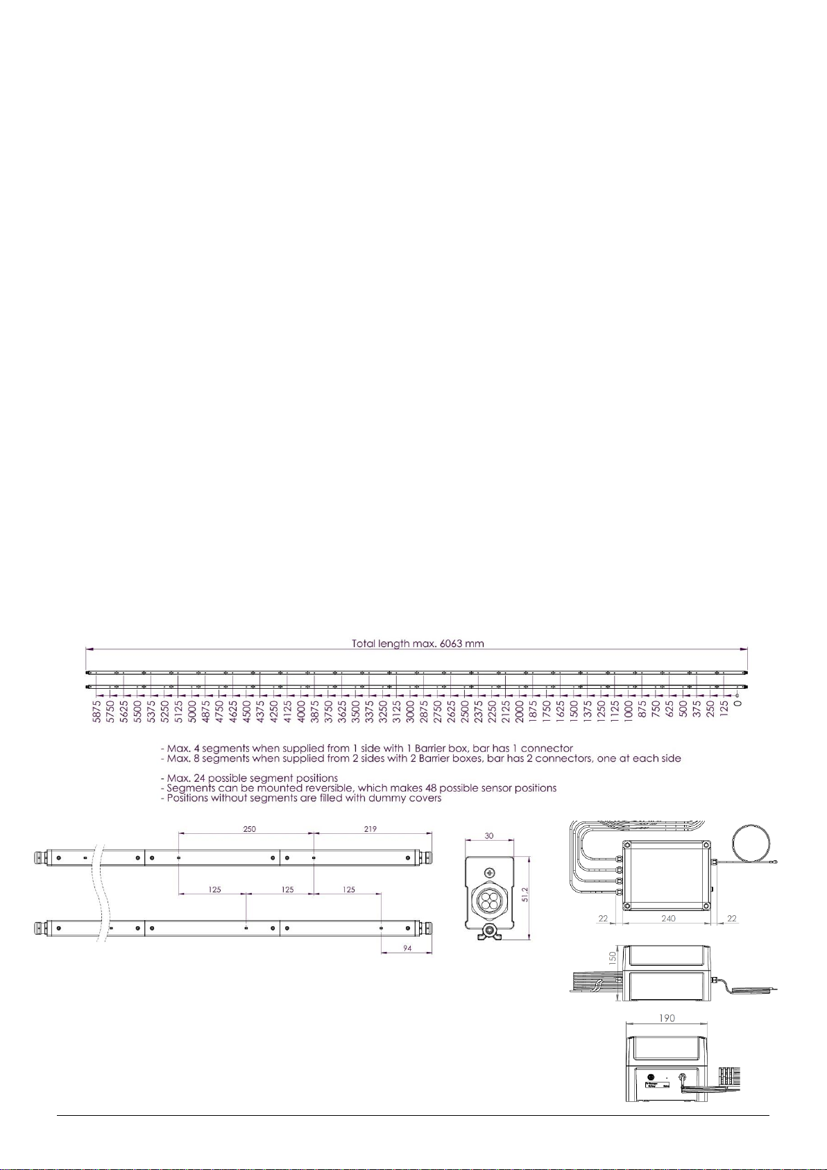
4 Technical specifications.................................................................................................................... 9
5 Installation .................................................................................................................................... 11
5.1 Checks .................................................................................................................................................11
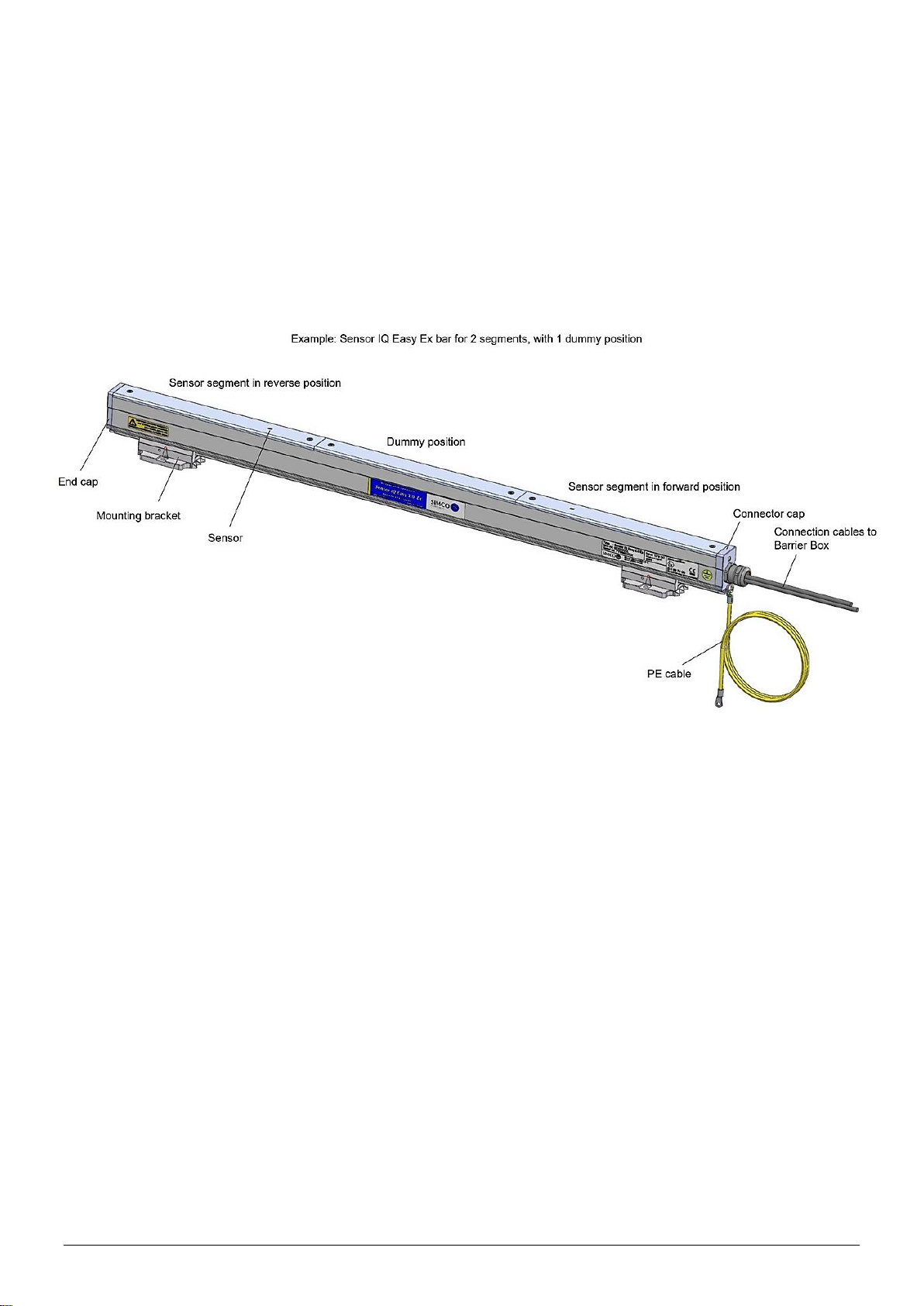
5.2 Installing segment units in the Sensor IQ Easy 2.0 EX bar.......................................................................11
5.3 Shortening the cable(s) between the Barrier Box and a Sensor IQ Easy 2.0 EX bar ..................................11
5.4 Placing the Sensor IQ Easy 2.0 EX..........................................................................................................13
5.5 Mounting bracket ................................................................................................................................14
5.6 Mounting Sensor IQ Easy 2.0 EX (slide bracket).....................................................................................15
5.7 Dismantling Sensor IQ Easy 2.0 EX (slide bracket)..................................................................................16
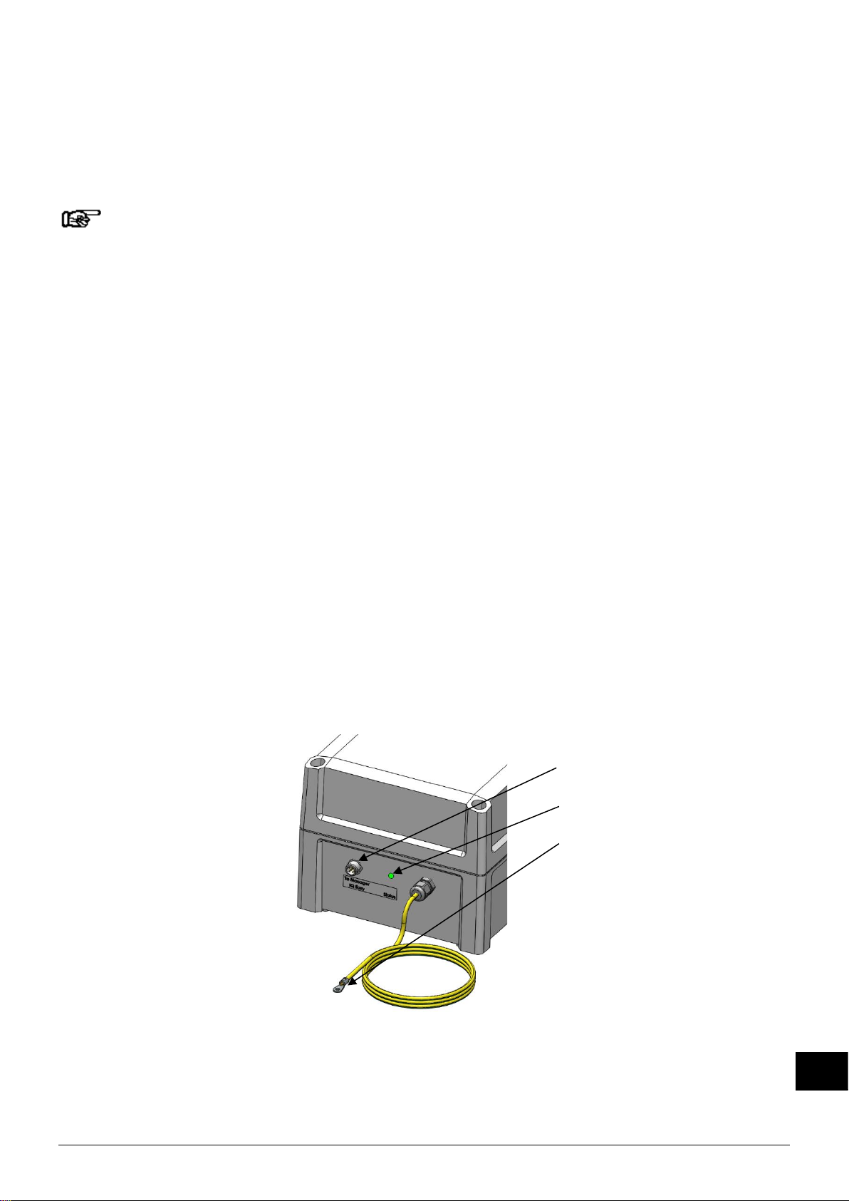
5.8 Connecting the Barrier Box...................................................................................................................16
6 Commissioning .............................................................................................................................. 17
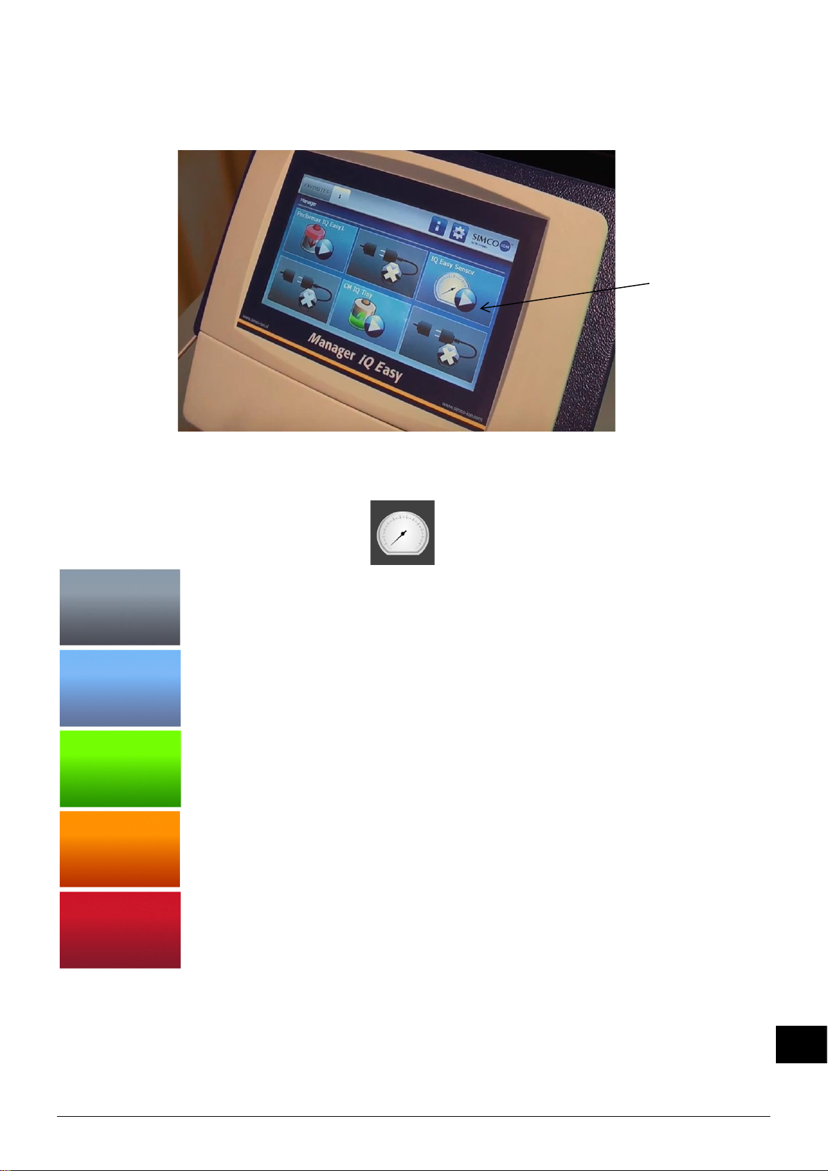
6.1 Commissioning the Sensor IQ Easy 2.0 EX using the IQ Easy Platform.....................................................17
6.2 Selecting EXPERT mode for setting parameters or allowing for maintenance .........................................17
6.3 Selecting mounting distance Sensor IQ Easy 2.0 EX (expert mode) ........................................................18
6.4 Set the warning maximum level (expert mode).....................................................................................18
6.4.1 Set the warning minimum level (expert mode)...................................................................................19
6.5 Setting the alarm maximum level (expert mode)...................................................................................19
6.5.1 Set the alarm minimum level (expert mode) ......................................................................................19
6.6 Setting warning/alarm error delay (expert mode) .................................................................................19
6.7 Sensor IQ Easy 2.0 EX Standby & Active ................................................................................................19
6.8 Setting bar information parameters (expert mode) ...............................................................................20
6.9 (De)activating active segments (expert mode) ......................................................................................20
6.10 (De)activating Datalogging (expert mode)...........................................................................................20
6.11 Switching the bar on/off remotely through the remote on/off input on the manager or using fieldbus
(expert mode) (will be implemented in the software later) .........................................................................20
7 Functional check ............................................................................................................................ 21
7.1 Functional check ..................................................................................................................................21
7.2 Functional check via the Manager IQ Easy.............................................................................................21
7.2.1 Information tab..........................................................................................................................................................21
7.2.2 Graphics tab...............................................................................................................................................................22
7.2.3 Action log tab.............................................................................................................................................................22
7.2.4 Data log tab................................................................................................................................................................22

SensorIQEasy2.0EX_UM_GB_V2_0 3
GB
8 Maintenance ................................................................................................................................. 22
8.1 Cleaning the Sensor IQ Easy 2.0 EX........................................................................................................22
9 Faults ............................................................................................................................................ 23
10 Repairs and calibration ................................................................................................................ 24
11 Disposal....................................................................................................................................... 24
Spare parts....................................................................................................................................... 24

SensorIQEasy2.0EX_UM_GB_V2_0 4
Preface
This manual is intended for installation and use of the Sensor IQ Easy 2.0 EX.
This manual must be available at all times to staff operating the equipment.
Read through the entire manual before installing and commissioning the product.
Follow the instructions set out in this manual to ensure proper operation of the product and to
retain your entitlement under the guarantee.
The guarantee terms are set out in the General Terms and Conditions of Sale of
SIMCO (Nederland) B.V.
Explanation of symbols
Warning
Indicates special information to prevent injury or significant damage to the
product or the environment.
Note
Important information for making the most efficient use of the product
and/or for preventing damage to the product or the environment.
[ ] If there are icons between the [ ], it may be necessary to first select the icons
between [ ] before you can go to the desired page with follow-up
instruction(s).
Using buttons you can scroll through the various pages.

SensorIQEasy2.0EX_UM_GB_V2_0 5
GB
1 Introduction
The Sensor IQ Easy 2.0 EX is designed for monitoring electrostatic charge. It consists of 2
parts, the Sensor IQ Easy 2.0 EX bar and a Barrier Box. The Sensor IQ Easy 2.0 EX bar itself is
constructed to be used in specific explosion hazardous areas, see chapter 3, Safety.
Note:
The Barrier Box should be placed outside the hazardous area!
Up to 8 sensor segments can be placed in a Sensor IQ Easy 2.0 EX. And up to 4 sensor
segments can be connected to 1 Barrier Box. The Sensor IQ Easy 2.0 EX will function optimally
at a distance of between 10 and 300 mm to the material and is available in lengths of 267 mm
to 6017 mm (with max. 8 sensors and max. 2 Barrier Boxes connected). Segments positions
are available in increments of 250 mm. And segments could be rotated 180 degrees in there
bay, so increments of 125 mm between the measuring elements of 2 segments could be
accomplished.
Each sensor segment can be placed at a strategic position above the material web for
measuring/monitoring the electrostatic charge. All data from each sensor segments is
communicated to the Barrier Box and then communicated to the Manager IQ Easy. In the
Manager IQ Easy data can be stored for process monitoring.
Data received from the sensor segments can also be used for quality and process control.
The log data can be retrieved from the Manager IQ Easy via the standard Ethernet port or an
attached USB flash drive.
The Sensor IQ Easy 2.0 EX gets it power from the Barrier Box and the Barrier Box is supplied
with 24 V DC supply voltage from the Manager IQ Easy through a standard 5-pin M12
connector. Also, the Barrier Box is provided with 1 LED for (status, warning and alarm).
Safety earth
M12-5pol to Simco-ION IQ Manager
Status LED
Figure 1: Connecting Simco-ION Barrier Box

SensorIQEasy2.0EX_UM_GB_V2_0 6
2 Description and operation
The Sensor IQ Easy 2.0 EX consists of a bar-shaped aluminium profile. On one or two sides of
this profile there are outlets for cables. These cables run to a Barrier Box.
The configuration of max. 4 bay’s and max. 4 segments connected to 1 Barrier Box could be
placed a second time mirrored in the profile to get up to max. 8 bay’s and max. 8 segments in
one profile. Between the bay’s there are dummy’s placed that cover up the empty spaces on top
of the profile.
Figure 2: Make-up Sensor IQ Easy 2.0 EX

SensorIQEasy2.0EX_UM_GB_V2_0 7
GB
Configuring the Sensor IQ Easy 2.0 EX is done through the Manager IQ Easy.
All data from each sensor is communicated to the Manager IQ Easy and is stored for process
control.
The background colour of the sensor icon displays the status of the Sensor.
Inactive or no communication
Active and operating OK, without warnings or alarms
Standby, waiting for start command
Active, but with a warning
Active, but with an alarm
Figure 3: Manager IQ Easy
Menu
Sensor IQ
Easy 2.0 EX

SensorIQEasy2.0EX_UM_GB_V2_0 8
3 Safety
The following safety guidelines must be observed in order to prevent physical injury and
damage to objects or to the Sensor IQ Easy 2.0 EX itself.
Warning:
- The Sensor IQ Easy 2.0 EX is designed solely for measuring electrostatic charge.
- The electrical installation and repair must be carried out by an electrical engineer with the
relevant training and qualifications and in accordance with the applicable national and
local regulations.
- The Sensor IQ Easy 2.0 EX can only be supplied and connected to the Barrier Box.
- Before using the Sensor IQ Easy 2.0 EX in an explosive hazardous area, check whether
it is permitted to be used in the zone classification of the hazardous area.
- The Sensor IQ Easy 2.0 EX is suitable for ATEX II 2G.
- The Sensor IQ Easy 2.0 EX should only be used in non-mining applications.
- The Sensor IQ Easy 2.0 EX may be used in gas zones 1 and 2 and is suitable for gas
groups IIA and IIB.
- To ensure the safe operation, the working temperature should be kept below 40ºC.
- Only the Sensor IQ Easy 2.0 EX should be installed in Ex-zone environments.
- The Barrier Box should NOT be installed in Ex-zone environments.
- Do not clean or open the Sensor IQ Easy 2.0 EX bar or the Barrier Box when an
explosive atmosphere is present.
- Do not place or remove segments when an explosive atmosphere is present.
- Do not power up the Sensor IQ Easy 2.0 EX when not all the bay positions have been
fitted with a segment or a blanking cover.
- There are no serviceable parts inside the Sensor IQ Easy 2.0 EX or in the Barrier Box.
- Do not expose the Sensor IQ Easy 2.0 EX bar and Barrier Box to mechanic shocks and
vibrations.
- Fit all the connecting cables in such a way there is no chance on mechanical damage of
the cables.
Note:
Making changes, adjustments etc. without prior written consent or carrying out repairs using
non-original parts will invalidate the device’s guarantee and could invalidate approvals.

SensorIQEasy2.0EX_UM_GB_V2_0 9
GB
4 Technical specifications
Required power supply
Supply voltage Barrier Box (Un)
Um
21 –27 VDC
250V
Max. Cable length from a
Manager IQ Easy to a Barrier Box
Connection
50 meter with min. conductor size 0,34 mm2
Standard industrial M12 5-pin connectors
Cable length from a Barrier Box to
a Sensor IQ Easy 2.0 EX
Number of segments
Maximum length is 15 meter (This cable(s) could not be self-
made and are supplied directly connected to the Sensor IQ
Easy 2.0 EX. They can only be shortened by the customer).
Number of segments
Max. 4 (1x Barrier Box), Max. 8 (2x Barrier Box)
Number of placeable bay
positions
Max. 8
Detection Range
0kV to 10kV @ 10mm
0kV to 30kV @ 20mm to 50mm
0kV to 50kV @ >100mm
Lower web voltages charges could be measured best on lower
mounting distance and vice versa.
Operating distance
10mm to 300mm
Environment
Use
Industrial, indoor use
Density class
IP52
Temperature
EX environment
Standards
-20°C to 40°C
IEC 60079-0:2017
IEC 60079-11:2011
EN IEC 60079-0:2018
EN 60079-11:2012
Barrier Box
[Ex ib Gb] IIB
2813 0518 II (2) G
Sensor Bar
Ex ib IIB T4 Gb
2813 0518 II 2 G

SensorIQEasy2.0EX_UM_GB_V2_0 10
Local signalling
LED on Barrier Box
Green, Continuously = In operation
Green, Flashing = Standby
Red = Alarm
Orange = Warning
See chapter 7 for all indications
Functions
(with IQ Easy platform)
The Sensor can be monitored using the Manager IQ Easy (see
also user manual Manager IQ Easy).
Mechanical
Sensor IQ Easy 2.0 EX
Length
267 mm to 6017 mm
Dimensions
without mounting brackets
including mounting brackets
Width
30 mm
Height
52 mm
Width
50 mm
Height
70 mm
Weight
2 kg/m
Housing material
Bare aluminium
Barrier Box
Dimensions
Width
190 mm
Height
150 mm
Length
240 mm
Weight
3 kg
Housing material
ABS/PC
Figure 4: Dimensions Sensor IQ Easy 2.0 EX and Barrier Box

SensorIQEasy2.0EX_UM_GB_V2_0 11
GB
5 Installation
Warning:
- The electrical installation and repair must be carried out by an electrical engineer
with the relevant training and qualifications and in accordance with the applicable
national and local regulations.
- The equipment must be properly earthed. Earthing is necessary to ensure proper
and safe operation in hazardous areas.
- Connect the 4mm² earth cable form the Barrier Box to an infallible earthing system.
- Connect the 4mm² earth cable form the Sensor IQ Easy 2.0 EX bar to an infallible
earthing system.
- Disconnect the power supply before carrying out any work on the unit.
- Only the Sensor IQ Easy 2.0 EX bar should be installed in Ex-zone environments.
- Before installing the Sensor IQ Easy 2.0 EX in an explosive hazardous area, check
whether it is permitted to be used in the zone classification of the hazardous area.
5.1 Checks
- Check the equipment for damage and whether you have received the correct version.
The segment units are supplied in a separate package, because the sensors are very
sensitive to falling and bumping.
- Check whether the data on the packing slip corresponds to the data shown on the
product received.
If you have any problems or are unsure, please contact Simco-ION or your regional agent.
5.2 Installing segment units in the Sensor IQ Easy 2.0 EX bar
- Remove the segment unit from the packaging.
- Make sure the right DIP switch setting is set for the desired segment number.

SensorIQEasy2.0EX_UM_GB_V2_0 12
- Place the segment in the desired bay of the Sensor IQ Easy 2.0 EX bar. The segment
unit can be fitted both ways in a bay.
- Then tighten the two bolts on the side of the segment unit.
Use a small screwdriver, not an electric screwdriver or cordless drill!
5.3 Shortening the cable(s) between the Barrier Box and a Sensor IQ Easy 2.0 EX bar
The maximum length of the cable(s) between the Barrier Box and the Sensor IQ Easy 2.0 EX is
15 meter. This cable(s) could not be self-made and are supplied directly connected to the
Sensor IQ Easy 2.0 EX. They can only be shortened by the customer.
Figure 5: Placing the Segment unit in the docking station

SensorIQEasy2.0EX_UM_GB_V2_0 13
GB
5.4 Placing the Sensor IQ Easy 2.0 EX
Note: Conductive machine parts close to an Sensor IQ Easy 2.0 EX may have a
negative influence on its effectiveness. For the best results the Sensor IQ Easy
2.0 EX should be mounted according to figure 6.
Mount the Sensor IQ Easy 2.0 EX:
•With the bar perpendicular in the direction of the material to be measured.
•If applicable behind an anti-static bar. At least 2x the operating distance of the anti-static
bar.
Figure 6: Position Sensor IQ Easy
•The measurement range of the Sensor IQ Easy 2.0 EX could be explaned by a
combination of 3 factors: the electrostatic web voltage charge, the mounting distance
between the measurement surface and the Sensor IQ Easy 2.0 EX and the size of the
measuring spot on the measurement surface.
Therefor it is important to set the correct mounting distance of the Sensor IQ Easy 2.0 EX
in the Manager IQ Easy, see H6.3. And to make sure that measuring spot of the Sensor
IQ Easy 2.0 EX on that distance is fully on the surface to be measured.
Lower web voltages charges could be measured best on lower mounting distance and
vice versa.
•0kV to 10kV @ 10mm
0kV to 30kV @ 20mm to 50mm
0kV to 50kV @ >100mm
Figure 6b: Visualization measuring angles and distances

SensorIQEasy2.0EX_UM_GB_V2_0 14
5.5 Mounting bracket
The Sensor IQ Easy 2.0 EX bar is supplied with at least two mounting brackets. Which could be
used to mount Sensor IQ Easy 2.0 EX in various ways.
The Barrier Box is supplied with 4 mounting brackets.
Note: Keep in mind that the plastic mounting brackets are not electrically
conductive. Make sure that the Sensor IQ Easy 2.0 EX is properly grounded (see chapter
5).
Figure 7a: Dimensions and mounting options for the brackets of the Sensor IQ Easy 2.0 EX bar.
Figure 7b: Dimensions and mounting options for the brackets of the Barrier Box

SensorIQEasy2.0EX_UM_GB_V2_0 15
GB
5.6 Mounting Sensor IQ Easy 2.0 EX (slide bracket)
- Attach the mounting feet (1) on the machine. The triangles (2) have to point in the same
direction. For mounting use appropriate M5 mounting material (3).
- Slide the brackets (4) onto the Sensor IQ Easy 2.0 EX (5).
Keep spacing of the brackets (4) and mounting foot (1) equal and lock the bracket (2)
with the set screw (6).
- Set the Sensor IQ Easy 2.0 EX with brackets onto the mounting feet and slide the
combination against the direction of the triangles.
- Lock the Sensor IQ Easy 2.0 EX in the mounting feet by screwing the two adjusting
screws (7) into the brackets. With more than two brackets, only the two outer brackets
need to be locked.
Figure 8: Fixing Sensor with mounting brackets

SensorIQEasy2.0EX_UM_GB_V2_0 16
5.7 Dismantling Sensor IQ Easy 2.0 EX (slide bracket)
- Unscrew the adjusting screws (nr. 7) from the brackets (see figure 8).
- Slide the Sensor IQ Easy 2.0 EX with brackets off the mounting feet, in the direction of the
triangles to the stop, then pull the Sensor IQ Easy 2.0 EX from the mounting feet straight up.
5.8 Connecting the Barrier Box
- Connect the Barrier Box to one of the outputs of the Manager IQ Easy, using an 1:1 M12
connection cable, Male-Female, 5 pins.
The standard M12 connector can be connected during operation of the Manager IQ Easy.
Hence, it does not need to be powered down.
Figure 9: Wiring
Warning:
- Connect the 4mm² earth cable form the Barrier Box to an infallible earthing system.
- Connect the 4mm² earth cable form the Sensor IQ Easy 2.0 EX bar to an infallible
earthing system.
- Only the Sensor IQ Easy 2.0 EX bar should be installed in Ex-zone environments.
brown
blue (GND)
yellow/green or gray
brown
black
white
white
yellow/green or gray
black
blue
Barrier Box
(View cable side)
Manager IQ Easy
(View cable side)

SensorIQEasy2.0EX_UM_GB_V2_0 17
GB
6 Commissioning
Note:
- The Sensor IQ Easy 2.0 EX will not function if the sensors are covered.
6.1 Commissioning the Sensor IQ Easy 2.0 EX using the IQ Easy Platform
-When the M12 connection cable connects the Barrier Box and the Manager IQ Easy,
communication will be established automatically, which is indicated by a flashing status LED
and a green background colour behind the emerging sensor symbol.
By default, the bar will become active after all information has been gathered by the
manager.
This is indicated by the background colour of the sensor display changing to green.
Please refer to the Manager IQ Easy user manual for a general explanation.
6.2 Selecting EXPERT mode for setting parameters or allowing for maintenance
In order to set parameters and carry out maintenance, you need expert user privileges. For this,
a password may be required. For a detailed description, please refer to chapter 6.4 of the
manual Manager IQ Easy.
Once logged in on this user level, you will remain on this level until selecting a new user level.
-Go to the main screen , select settings and choose expert.
-Enter the password and confirm with or return directly to the system settings page of
the manager, if no password is required.
-Click on and go to the device to check or change the parameters by clicking
behind the parameter or the desired action.
-By clicking you return to the main screen.

SensorIQEasy2.0EX_UM_GB_V2_0 18
6.3 Selecting mounting distance Sensor IQ Easy 2.0 EX (expert mode)
For an accurate measurement the mounting distance whereupon the Sensor IQ Easy 2.0 EX is
mounted needs to be entered. By default, this is set to 50mm. If the value of this parameter
departs from the actual mounting distance the measure value displayed will not correspond with
the actual value.
Select the Sensor
Now the Information tab of the sensor is displayed.
Indicate that you want to change settings by choosing the settings button
The information Tab consists of several pages. With the buttons you can scroll through
the various pages.
Find the parameter Mounting distance sensor and select
Enter the mounting distance.
Confirm the value entered using . When the Sensor IQ Easy 2.0 EX is used at short
distance and the Mounting distance parameter is set to a value less than 50 mm, the Web
voltage parameters are displayed with extra accuracy to 3 decimal places.
6.4 Set the warning maximum level (expert mode)
The Sensor IQ Easy 2.0 EX bar will generate a warning if a segments measured value reaches
the Warning set point (during warning/error delay see 6.6 ).
This value is set to 5kV by default, but it can be easily adjusted:
- [ (n)x “Warning maximum level”
slide slider or use to go to the desired value and confirm with ].

SensorIQEasy2.0EX_UM_GB_V2_0 19
GB
6.4.1 Set the warning minimum level (expert mode)
The Sensor IQ Easy 2.0 EX bar will generate a warning if a segments measured value reaches
the Warning set point (during warning/error delay see 6.6 ).It can be easily adjusted:
- [ (n)x “Warning minimum level”
slide slider or use to go to the desired value and confirm with ].
6.5 Setting the alarm maximum level (expert mode)
The Sensor IQ Easy 2.0 EX will generate a alarm if a segments measured value reaches the
Alarm set point (peak) (during warning/error delay see 6.6).
This value is set to 10kV by default, but it can be easily adjusted:
- [ (n)x “Alarm maximum level”
slide slider or use to go to the desired value and confirm with ].
6.5.1 Set the alarm minimum level (expert mode)
The Sensor IQ Easy 2.0 EX will generate a alarm if a segments measured value reaches the
Alarm set point (peak) (during warning/error delay see 6.6). It can be easily adjusted:
- [ (n)x “Alarm minimum level”
slide slider or use to go to the desired value and confirm with ].
6.6 Setting warning/alarm error delay (expert mode)
The Sensor IQ Easy 2.0 EX will generate a warning if a segments measured value continually
exceeds the set point during warning/error delay.
This value is set to 5 seconds by default, but it can be easily adjusted:
- [ (n)x “Warning/alarm delay”
enter the desired value and confirm with ].
6.7 Sensor IQ Easy 2.0 EX Standby & Active
By default, the bar will become active after all information has been gathered by the manager.
You can set the device in standby or active mode on each tab.
The status is indicated in the left upper corner by means of a colour behind the icon:
Green = standby, blue = running, orange = warning, red = alarm.

SensorIQEasy2.0EX_UM_GB_V2_0 20
6.8 Setting bar information parameters (expert mode)
If desired, various information parameters can be entered as required to make the different
devices more recognisable.
If desired, adjust the parameters: Device name, Machine position,
These are information parameters neither the bar nor the manager will use for calculations.
- Select the information page with the parameters to be changed by:
- [ , , (n)x “parameter “, enter name or value”, confirm with ]
6.9 (De)activating active segments (expert mode)
If desired, sensor segments can be activated or deactivated.
The sensor segments present are set to active by default so that they all contribute to the
calculation of the average values.
If a segment is no longer in front of the object or film to be measured, this segment has to be
deactivated, as the average value calculation will be incorrect otherwise.
- [ (n)x “Active segments”
By clicking the segment in question it will be deselected or selected, consecutively. Choose
from the segments and confirm with ]
6.10 (De)activating Datalogging (expert mode)
If desired, the manager can log measurement values and data regarding the operation of the
bar.
To (de)activate this data logging, the parameter Data logging has to be changed.
For detailed information on datalogging, please refer to the manual of the Manager IQ Easy.
- [ (n)x “Data logging” select On or Off ]
6.11 Switching the bar on/off remotely through the remote on/off input on the manager or
using fieldbus (expert mode) (will be implemented in the software later)
If desired, the manager can be switched on and off using the remote on/off input of the Manager
or by means of an instruction of the optional Fieldbus.
With this, one machine control can switch several selected devices, including this bar, on/off at
the same time without having the operator to perform actions for this.
For selecting this, the Remote on/off source parameter has to be changed from Continuous to
Remote or Fieldbus.
- [ (n)x “Remote on/off source” select Remote or Fieldbus ]
Table of contents
Other ITW Accessories manuals
Popular Accessories manuals by other brands

Lifetime
Lifetime Elite 51546 Owner's manual with assembly instructions

CAS
CAS NT-500 Series owner's manual

WAREMA
WAREMA 310 Instructions for use and maintenance

Philio Technology Corporation
Philio Technology Corporation PST02-A manual

Vision
Vision ZF 5201 IN Installation & operation manual

RKI Instruments
RKI Instruments 65-2511RK operating manual