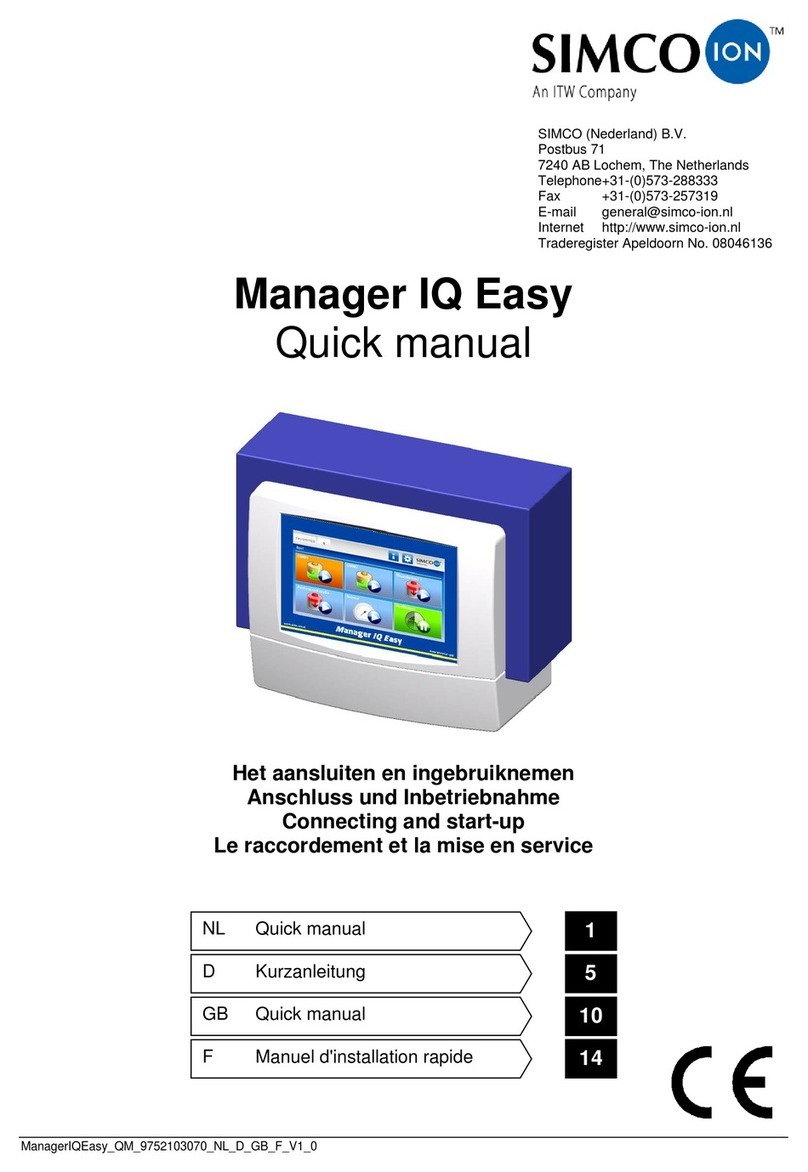
ITW SIMCO ION Manager IQ Easy User manual

ManagerIQEasy_UM_9752103002_GB_V3_1
Manager IQ Easy
Control unit
SIMCO (Nederland) B.V.
Postbus 71
NL-7240 AB Lochem, The Netherlands
Telephone +31 (0)573-288333
Fax +31 (0)573-257319
Internet http://www.simco-ion.nl
Trade Register Apeldoorn No. 08046136

ManagerIQEasy_UM_9752103002_GB_V3_1 1
CONTENTS
Preface............................................................................................................................................... 4
Explanation of symbols....................................................................................................................... 4
1 Introduction..................................................................................................................................... 5
2 Description and operation................................................................................................................ 6
3 Safety.............................................................................................................................................. 8
4 Technical specifications.................................................................................................................... 9
5 Systems ......................................................................................................................................... 11
5.1 Checks .................................................................................................................................................11
5.2 General................................................................................................................................................ 11
5.3 Fitting the Manager IQ Easy..................................................................................................................11
5.4 Electrical installation............................................................................................................................12
5.4.1 AC variant ..................................................................................................................................................................13
5.4.2 24V DC variant...........................................................................................................................................................13
5.4.3 Connecting Devices ...................................................................................................................................................13
5.4.4 Machine I/O Input and output connections.............................................................................................................. 14
5.4.4.1 Digital outputs........................................................................................................................................................14
5.4.4.2 Remote on/off input............................................................................................................................................... 15
5.4.5 (Fieldbus) connection ................................................................................................................................................15
5.4.6 Ethernet connection..................................................................................................................................................15
5.4.7 Serial communication COM ports .............................................................................................................................16
5.4.8 Installing the protective cover................................................................................................................................... 16
5.5 Mounting the Manager in a machine panel...........................................................................................16
6 Commissioningand operation ........................................................................................................ 21
6.1 Terminology used ................................................................................................................................ 22
6.2 Switching on the Manager IQ Easy........................................................................................................23
6.3 The main screen...................................................................................................................................24
6.4 Devices................................................................................................................................................ 26
6.5 Operating modes ................................................................................................................................. 27
6.5.1 Standby and Run ....................................................................................................................................................... 27
6.5.2 Autorun mode ...........................................................................................................................................................27
6.6 Remote on/off.....................................................................................................................................28
6.7 Status information ...............................................................................................................................29
6.8 (Userlevels).......................................................................................................................................... 31
6.9 Selecting a different (Userlevel)............................................................................................................32
6.10 Special Service access codes ...............................................................................................................34
6.11 Device information screens ................................................................................................................35
6.11.1 Tab “Information” (Information) / “Settings” (Settings) ......................................................................................... 35
6.11.2 Tab “Graphics”......................................................................................................................................................... 38
6.11.3 Tab “ActionLog”.......................................................................................................................................................39
6.11.4 Tab “DataLog” ......................................................................................................................................................... 40
6.11.5 Tab “Maintenance” .................................................................................................................................................41

ManagerIQEasy_UM_9752103002_GB_V3_1 2
6.12 Changing a parameter ........................................................................................................................43
6.13 Overview of HMI parameters ............................................................................................................. 48
6.14 Overview of Backplane / ExtensionBox parameters.............................................................................51
6.15 Overview of common Device parameters............................................................................................ 54
6.16 Switching off the Manager IQ Easy......................................................................................................56
6.17 Changing some commonly used parameters .......................................................................................58
6.17.1 Setting the user language of the HMI (Expert user)................................................................................................58
6.17.2 Setting the system time (Expert user) .....................................................................................................................59
6.17.3 Setting the date display ((Expert user))................................................................................................................... 60
6.17.4 Setting a password for the ‘Advanced user’ user level ...........................................................................................61
6.17.5 Setting a password for the ‘Expert user’ user level.................................................................................................62
6.17.6 Resetting the Advanced user password (Expert user)............................................................................................. 63
6.17.6 Resetting the Expert user password (Expert user) .................................................................................................. 64
6.17.8 Users Standby/Run control level (Expert user) ....................................................................................................... 65
6.17.9 Setting Logging of Sensor Peak values (Expert user)...............................................................................................66
6.17.10 Setting the Run state display colour green (Expert user)......................................................................................67
6.17.11 Reading network IP address (Expert user) ............................................................................................................ 68
6.18 Linking and disconnecting Devices (Expert user)..................................................................................69
6.18.1 Linking a member with a Sensor Device (Expert user) ............................................................................................69
6.18.2 Linking a Sensor Device to a bar (Expert user) ........................................................................................................ 71
6.18.3 Activating the CLFB voltage control (Expert user)...................................................................................................74
6.18.4 Disconnecting a coupled bar from the Sensor Device (Expert user) ....................................................................... 76
6.18.5 Disconnecting a Sensor Device from a bar (Expert user) ........................................................................................78
6.18.6 Disconnecting a Device from a deleted Sensor Device (Expert user)...................................................................... 81
6.18.5 Disconnecting a Sensor Device from a deleted bar (Expert user) ...........................................................................83
6.19 Activating and deactivating sensor segments (Expert user, Sensor version V5_2 only) ..................................86
6.19.1 Activating and deactivating sensor segments via the settings screen (Expert user)............................................... 86
6.19.2 Activating and deactivating sensor segments via the Graphics screen (Expert user) ....................................................87
6.20 Enabling and disabling Sensor segments (Expert user).........................................................................88
6.20.1 Enabling and disabling Sensor segments via the settings screen (Expert user) ...................................................... 88
6.20.2 Enabling and disabling Sensor segments via the Graphics screen (Expert user).....................................................89
6.20.3 Enabling and disabling Sensor segments via a linked bar (Expert user)................................................................. 90
6.21 Checking and monitoring System Configuration (Expert user)..............................................................91
6.21.1 Switching on the system configuration check for the first time (Expert user)........................................................92
6.21.2 Saving custom system configuration (Expert user) .................................................................................................93
6.21.3 Temporarily/permanently deactivate System Configuration Check (Expert user)..................................................94
6.21.4 Re-enabling System Configuration Check (Expert user)..........................................................................................95
6.21.5 Temporarily disabling System Configuration Alarm notification (Expert user)....................................................... 96
6.22 Setting up an FTP connection (Expert user) ......................................................................................... 97
6.22.1 Standard FTP login username and password. ......................................................................................................... 97
6.22.2 Users FTP login username and password................................................................................................................ 97
6.22.3 Setting up an FTP connection with Edge. ................................................................................................................97
6.22.3 Setting up an FTP connection with IExplore............................................................................................................ 97
6.22.5 Setting up an FTP connection with Windows Explorer. ..........................................................................................99
6.22.3 Setting up an FTP connection with FileZilla...........................................................................................................101
6.23 Copying log files to a USB stick.......................................................................................................... 105
6.24 Copying log files including Simco Debug files to a USB stick (Service) ................................................. 106
6.25 Backing up system parameters to USB (Expert user).......................................................................... 107
6.26 Restoring system configuration from a backup (Expert user) ............................................................. 109
6.27 Searching for newly added Extension IQ Easy units ........................................................................... 111
6.27.1 Searching manually for Extension IQ Easy units....................................................................................................111

ManagerIQEasy_UM_9752103002_GB_V3_1 3
6.27.2 Searching manually for Extension IQ Easy units....................................................................................................112
6.28 Disconnecting a Device (Expert user) ................................................................................................ 113
6.28.1 Device disconnected notification. .........................................................................................................................113
6.28.2 Restoring a disconnected Device...........................................................................................................................114
6.28.3 Removing the Disconnected Device from the IQ Easy system. .............................................................................115
6.29 Replacing a defective Device (Expert user) ........................................................................................ 116
6.29.1 The Device information is still available in the memory of the Manager IQ Easy.................................................116
6.29.2 The Device information is stored on the system...................................................................................................116
6.29.3 There is no longer any information from the defective Device available for the Manager IQ Easy. ....................117
6.30 Calibrating a bar (Expert user) .......................................................................................................... 118
6.31 Fieldbus settings (Expert user).......................................................................................................... 119
6.31.1 Setting up the use of a DHCP server......................................................................................................................119
6.31.2 Setting the network parameters with IPconfig tool (ProfiNet and EtherNet/IP only). .........................................120
6.31.2.1 Setting the Fieldbus network parameters using a DHCP server.........................................................................121
6.31.2.2 Setting the Fieldbus network parameters without using a DHCP server. ..........................................................122
6.31.3 Setting the parameters “Domain name”, “Host name” (ProfiNet and EtherNet/IP only)...................................................124
6.31.4 Setting the network Device name (ProfiNet only) ................................................................................................ 126
6.31.5 Setting the “Fieldbus Device ports” mapping parameter(s)..................................................................................129
6.31.6 Setting the “Fieldbus smart sensor data msg” parameter ....................................................................................133
6.31.7 Meaning of status LEDs Fieldbus module..............................................................................................................134
6.31.7.1 Meaning of status LEDs EthetNet/IP Fieldbus module.......................................................................................134
6.31.7.2 Meaning of status LEDs of the Profinet Fieldbus module ..................................................................................135
6.31.8 Setting up PLC for fieldbus communication ..........................................................................................................135
7 Functional check .......................................................................................................................... 136
7.1 Warnings ........................................................................................................................................... 136
7.2 Alarms............................................................................................................................................... 136
7.3 Data logging (as of Software version V1.1.0 of the Manager)............................................................... 136
7.3.1 Copying data from internal memory to PC..............................................................................................................137
7.3.2 Data logging to USB.................................................................................................................................................137
8 Maintenance ............................................................................................................................... 138
9 Solving malfunctions and problems.............................................................................................. 139
10 Repairs ...................................................................................................................................... 142
11 Scrapping .................................................................................................................................. 142
Spare parts..................................................................................................................................... 143

ManagerIQEasy_UM_9752103002_GB_V3_1 4
Preface
This manual is intended for the installation and use of the MANAGER IQ EASY.
This manual describes the installation and basic menus of the Manager itself. The different
possibilities of the connected equipment using the Manager is described in detail in the manual
of the relevant Device.
The term ‘Devices’ in this manual refers to Simco-Ion 24V DC equipment suitable for connecting
to the Manager IQ Easy.
This manual must be available at all times to staff operating the equipment.
Read through the entire manual before installing and commissioning the product.
Follow the instructions set out in this manual to ensure proper operation of the product and
to retain your entitlement under the guarantee.
The guarantee terms are set out in the General Terms and Conditions of Sale of SIMCO
(Nederland) B.V.
Explanation of symbols
The following symbols may appear in this manual or on the product.
Warning
Indicates special information to prevent injury or significant damage to the
product or the environment.
Danger
Indicates information for preventing electric shocks.
Attention!
Important information for making the most efficient use of the product
and/or for preventing damage to the product or the environment.

ManagerIQEasy_UM_9752103002_GB_V3_1 5
1 Introduction
The Manager IQ Easy is equipped with an on/off switch, 6 connectors for connecting Simco-Ion
equipment (Devices), various I/O connectors and a 7” touchscreen as a user interface. The user
interface is in colour and can be easily operated using a finger or stylus.
Using the Manager IQ Easy, Simco-Ion equipment can be configured, read out, monitored and
controlled. Also, you can easily control the quality, using the data and action logging feature on
the Manager. You can read out this data with an FTP connection through the Ethernet connection
or copy it to an external USB drive.
Remote control is possible using an optional Fieldbus and through the machine I/O connector
with which different digital and analogue in- and outputs can be configured.
To further expand the system to up to 30 Devices, the system has 2 serial COM connectors for
connecting Extension IQ Easy control units.
The Manager IQ Easy is available with 24V DC input and as a universal 100-240V AC 50-60Hz
version. A special version of the Manager IQ Easy is also available that can be used with
‘emergency-off’ installations, whereby the Manager IQ Easy remains supplied with voltage,
while the Devices are de-energised in an emergency-off situation. As a result, the Devices can
no longer deliver high voltage, which creates a safe environment in an ‘emergency-off’ situation.
Each Device port provides the 24V DC supply voltage and the communication with the Device.
All Device ports and other I/O ports are controlled through the internal Backplane IQ Easy interface.
Figure 1, Manager IQ Easy
7" touchscreen
Mains input with
Power switch-
6 Device connectors
Fieldbus (optional)
Machine I/O-connector
Ethernet connector
USB-connectors
Serial comm-connectors

ManagerIQEasy_UM_9752103002_GB_V3_1 6
2 Description and operation
After starting the Manager IQ Easy, it will display the status of the connected equipment on the
main screen.
Six possible Devices are displayed on the main screen. The operating status of each Device
can be read directly through the colours and icons used.
If you require more information regarding a specific Device, you can retrieve this information by
pressing the appropriate icon.
4 tabs will then be displayed. If a tab has several pages, you can scroll through them, using the
and the buttons. Each tab contains specific information about the connected device,
which will vary for each type of device. More or less information is displayed depending on the
log-in level for the user level.
Information: Various parameters, settings, limit values, operation modes and current readings
are displayed in a list.
Graphics: Graphical representations of current measurement values of the Device
ActionLog: List of status changes of the Device with date and timestamp.
DataLog: List of readings with date and timestamp.
Maintenance: Possible maintenance instructions.

ManagerIQEasy_UM_9752103002_GB_V3_1 7
On each tab, you can set the Device to standby or active mode.
Specific information of each tab is described in the manual of the corresponding Device.

ManagerIQEasy_UM_9752103002_GB_V3_1 8
3 Safety
The following safety guidelines must be observed in order to prevent physical injury and
damage to objects or the Manager IQ Easy itself.
Warning:
-Electrical installation must be carried out by a qualified electrician in accordance with
national and local regulations.
-The Manager IQ Easy must not be used in any environment where there are fire or
explosion hazards.
-The Manager IQ Easy must not be exposed to vibrations or shocks.
-Use the Manager only in combination with matching Simco-Ion equipment.
-Also read the manual of the equipment to be connected before commissioning.
-The Manager IQ Easy is not intended as a safety component in machines.
-Do not install the manager in dirty, damp or any other areas in which chemicals or other
corrosive materials are used.
Danger:
-Make sure that the equipment is properly earthed. Earthing is necessary to ensure proper
and safe operation and to prevent electric shocks upon contact.
The AC version is earthed through the power cable. Plug this into an earthed outlet.
With the 24 V DC version, the earthing connector of the 24 V power connector has to be
connected to the machine earthing or an earthed machine part.
-To guarantee safe operation, keep the Manager IQ Easy free of dirt, dust and moisture.
-The Device may only be serviced by qualified Simco-Ion staff.
Note:
- Making changes, adjustments etc. without prior written consent or carrying out repairs using
non-original parts will invalidate the Device’s guarantee.
Except for the 230 AC input connector, all connectors for the Devices and various I/O have
signals that are working on a safe 24V DC.
That is why all these inputs and outputs can be connected and disconnected safely while the
Manager IQ Easy is operating.

ManagerIQEasy_UM_9752103002_GB_V3_1 9
4 Technical specifications
Supply voltage
100 –240V AC nom. (90 –305V AC)
24V DC - 3/+10%
Frequency
50 –60Hz nom. (47 –63Hz)
Max power consumption
300W (100 –240V AC version)
360W (@15A) (24V DC version)
Purpose
Industrial, indoor use
Protection class
IP52
Operating temperature
0 - 55°C
Installation
Free of dust and vibration-
Free of dust and vibration
100 –240V AC version
24V DC 3A max. per port, total max. 9A
Device output 24V DC version
24V DC 3A max. per port, total max. 13A
Machine I/O
Digital inputs
10 –30 V 25mA max.
Analog input
0 –10V 0.6mA / 0 - 20mA / 4 –20mA
Digital outputs
OE/OC 24V DC nom. max. 30V 25mA
USB
3x USB 2.0
Ethernet
1x RJ45 8-pin connector
Fieldbus (optional)
1x Anybus interface
Weight
5,5 kg (100 –240V AC version)
3,9 kg (24V DC version)
Figure 2, Dimensions Manager IQ Easy and Extension IQ Easy
2 Suspension points
Mounting eyelet

ManagerIQEasy_UM_9752103002_GB_V3_1 10
Figure 3, Drilling template Manager IQ Easy and Extension IQ Easy

ManagerIQEasy_UM_9752103002_GB_V3_1 11
5 Systems
Warning:
- The electrical installation must be carried out by an electrical engineer with the
relevant training and qualifications.
- Disconnect the power supply before carrying out any work on the unit.
- Consult the manuals of the Device to be connected for proper and safe connecting
and use of the Device.
5.1 Checks
- Check that the equipment is undamaged and that you have received the correct version.
- Check that the packing bill data matches the data of the product received.
- Check whether the voltage shown on the rating plate corresponds to the mains voltage you
intend to use.
If you have any problems or are unsure, please contact Simco-Ion or your regional agent.
5.2 General
Place the Manager on a well visible and easily accessible place on or nearby the machine.
5.3 Fitting the Manager IQ Easy
The Manager IQ Easy can be placed on a flat surface or mounted in a machine panel.
Figure 4, Removal of the plastic bottom cover Manager IQ Easy and Extension IQ Easy.

ManagerIQEasy_UM_9752103002_GB_V3_1 12
Mounting on a flat surface:
- Remove the plastic bottom cover of the Manager by bending the side flaps slightly outward
and sliding the cover up.
- Use the supplied drilling templates to mark the mounting holes. Make sure that there is sufficient
space at the bottom for installing the cables.
- Drill the mounting holes into the mounting surface, mount suitable bolts into the two top holes
and allow the bolts to stick out 2.5 mm.
- Hang up the Manager with suspension points behind the bolt heads.
- Secure the lower mounting eye of the Manager with a suitable bolt.
5.4 Electrical installation
Warning:
- Disconnect the power supply before carrying out any work on the unit.
- The electrical installation must be carried out by an electrical engineer with the relevant
training and qualifications.
-Make sure that the equipment is properly earthed. Earthing is necessary to ensure
proper and safe operation and to prevent electric shocks upon contact.
With the AC version, plug the power cable into an earthed outlet.
With the 24 V DC version, the earthing connector of the 24 V power connector has to
be connected to the machine earthing or an earthed machine part.
- Connect the Manager IQ Easy according to the locally applicable regulations.

ManagerIQEasy_UM_9752103002_GB_V3_1 13
5.4.1 AC variant
- Plug the power cable into the IEC connector and plug the outlet plug into an earthed wall outlet.
5.4.2 24V DC variant
–Connect the 24 V DC power connector as shown in figure 5.
–Connect the earthing (ground) point with an earthed machine part or a shared earthing point.
Figure 5, 24 V-input Manager IQ Easy
5.4.3 Connecting Devices
Six M12 Device ports are available for connecting various Simco-Ion Devices. Connect the
Devices with the appropriate M12 Device ports 1 to 6.
Connecting is possible using standard cables with M12 5-pin male-female connectors.
The length of the cables is limited since the supply voltage of the Devices is also routed through
this cable. If the desired length exceeds the maximum specified length, a cable with a larger
diameter for the used wires may be selected, so that the required supply voltage is still available
during operation.
For this, Simco-Ion provides separate M12 5-pin connectors for connecting these cables
(the connection between the Manager and the Device is 1:1) see also Figure 6.
Figure 6, Wiring Device to Manager IQ Easy and Extension IQ Easy
If an old generation (non-IQ) Device is used, preferably connect this with ports 5 or 6 IQ/non-IQ.
These ports can be configured so that Remote On/Off and operation OK feedback can be processed
by the Manager IQ.
For this, use regular 1:1 male-female cables with M12 5-pin connectors as well.
brown
blue (GND)
yellow/green or grey
brown
black
white
white
yellow/green or grey
black
blue
Device
(View cable side)
Manager / Extension IQ Easy
(View cable side)

ManagerIQEasy_UM_9752103002_GB_V3_1 14
5.4.4 Machine I/O Input and output connections
The Manager IQ Easy has a 25-pin Sub D connector where various in- and output signals are
available. These can easily be connected to a machine controller or PLC, making it possible to
transmit warnings and alarms to the machine.
5.4.4.1 Digital outputs
The digital output signals indicate the status of the Devices connected to the Manager IQ Easy
and are available for connection to a machine controller (PLC).
The digital outputs can be configured in the Manager both as Open Collector (OC) and Open
Emitter (OE). For this, see Section 6.12 and 6.14. By default, these are configured as Open Emitter.
The output is then switched from the 24 V DC.
The PLC input can then be connected to the external GND.
For connecting these, see figure 7.
Figure 7, Wiring digital outputs on the machine interface connector
Available signals:
-19: “All system functions OK” –indicates that the Manager and all connected Devices are
functioning properly.
-18: “Global warning” –indicates that the Manager or a connected Device is generating
a warning.
-17: “Global Alarm” –indicates that the Manager or a connected Device is generating an
alarm.

ManagerIQEasy_UM_9752103002_GB_V3_1 15
5.4.4.2 Remote on/off input
Each connected Device can be switched via the remote on/off input.
How to connect the Device with this input is explained in the manual of the corresponding
Device (see the “Remote on/off source” parameter, Section 6.6).
-Connect an external 24 V switching signal between pins 24 and 25
(24V = Remote ON, 0V = Remote OFF)
-Or: Use the 24V DC output and connect a potential-free switching contact between pins
1 and 24 and create a connection between pin 3 and 25.
Figure 8, Wiring Remote on/off input on the machine interface connector
5.4.5 Fieldbus connection
With an optional Fieldbus connection (EtherNet/IP, ProfiNet, etc.), controls such as remote
on/off, warnings and alarms can be linked to a machine control (PLC). Setpoint settings and
reading back of readings are also possible when using a (Fieldbus).
For this, a (Fieldbus) interface module is mounted into the Anybus slot at the factory.
For connecting these fieldbuses, follow the general instructions applicable to these fieldbuses.
5.4.6 Ethernet connection
For transmitting datalog data from the Manager IQ Easy to a PC, the manager can be connected
to a network. For wiring, a standard UTP cable with an 8-pole RJ45 connector can be used.
An Ethernet IP address must be assigned by the network (using DHCP).
For retrieving the assigned IP address, see Section 6.17.11.

ManagerIQEasy_UM_9752103002_GB_V3_1 16
5.4.7 Serial communication COM ports
For expanding the system with more than 60 Devices, two COM ports are available to which
extension IQs can be connected. Standard cables with M8 3-pin male-female connectors can
be used for this. These are available from Simco-Ion
5.4.8 Installing the protective cover
- When all cables are connected, the cable protection cover can be mounted.
5.5 Mounting the Manager in a machine panel
Figure 9, Manager IQ Easy mounted in a machine panel
The Manager IQ Easy can be mounted into a machine panel so that only the plastic part of the
Manager is visible. The wiring will then be hidden behind the machine panel. The maximum
thickness of the machine panel is 6 mm.
Follow the steps below to mount the Manager IQ Easy.
- Drill and saw the necessary recesses and holds into the machine panel. Use the supplied
drilling template for this. Make sure you leave the required free space around the holes.

ManagerIQEasy_UM_9752103002_GB_V3_1 17
- The plastic front of the Manager IQ Easy is attached to the housing by means of 4 snap
connectors. Carefully pull away the plastic front from the housing. The plastic part can be loosened
using a larger flat screwdriver. There are two recesses below the plastic part for this.
Note: Do not pull on the wiring between the front and the housing.
- Remove all connectors from the front.
- Remove the M5 tap bolts and washers (1) and the 4 snap connectors (2 and 3) from the
housing.

ManagerIQEasy_UM_9752103002_GB_V3_1 18
- Place the housingbehind the machine panel and secure it with the 4 tap bolts and washers (1).
Make sure that the wires are not squeezed between the housing and the machine panel.
- Screw the four snap connectors into the housing through the machine panel.

ManagerIQEasy_UM_9752103002_GB_V3_1 19
- Mount the wiring connectors from the housing back onto the front.
- Click the front onto the four snap connectors on the machine panel.
Other manuals for SIMCO ION Manager IQ Easy
1
Table of contents
Other ITW Control Unit manuals
Popular Control Unit manuals by other brands

Keysight Technologies
Keysight Technologies N9029BV Product notes

HP
HP 75000 B Series user manual

SMC Networks
SMC Networks JSXF Series Operation manual

American Standart
American Standart Flash R950 installation instructions

STIEBEL ELTRON
STIEBEL ELTRON SBP 200 E Operation and installation

WAGO
WAGO 750-439/040-000 manual