manuals.online logo
Brands
  1. Home
  2. •
  3. Brands
  4. •
  5. SMC Networks
  6. •
  7. Control Unit
  8. •
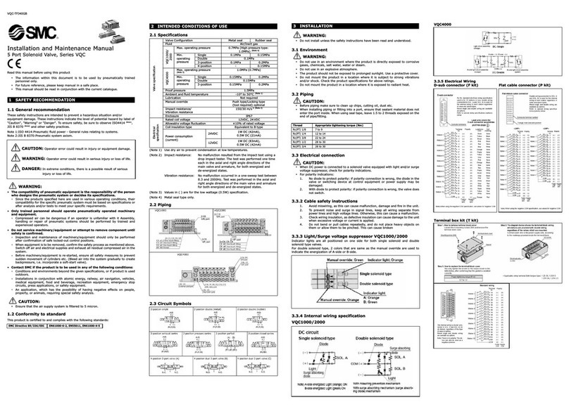
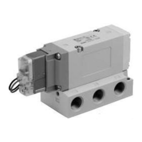
  9. SMC Networks JSXF Series User manual

SMC Networks JSXF Series User manual

PRODUCT NAME
Pulse Valve
SMARTVENT Type
MODEL / Series / Product Number
JSXF Series
Doc. No.
DOC1042447
NN61536600
-1-
Contents
Contents
..................................................................................................
P1
Safety Instructions ............................................................................................................................P2,3
1.Precautions for Design ..............................................................................................................P4
2.Precautions for Operating Environment..................................................................................P4,5
3.Precautions for Fluid ................................................................................................................P5
4.Material of Fluid .......................................................................................................................P5
5.Precautions for Mounting ......................................................................................................P5,6
6.Precautions for Piping ...........................................................................................................P6,7
7.Precautions for Wiring ..............................................................................................................P8
8.Notes on Appearance ..............................................................................................................P8
9.Maintenance and Inspection ....................................................................................................P9
10.Return of Our Products ..........................................................................................................P9
11.Model Indication and How to Order .....................................................................................P10
12.Specifications ..................................................................................................................P11,12
13.Component Drawing ............................................................................................................P12
14.Dimensions ..........................................................................................................................P13
15.Wiring ...................................................................................................................................P14
15.1.Wiring example and internal circuit ...............................................................................P14
15.2.Wiring work ....................................................................................................................P15
15.3.Wiring diagram ..............................................................................................................P15
15.4.Wiring to terminal blocks ...............................................................................................P16
16.Names and Functions of Board Components ......................................................................P17
16.1.Board for the base valve ...............................................................................................P17
16.2.Board for remote valves ................................................................................................P18
17.Operation Modes and How to Set a Mode ...........................................................................P19
17.1.Continuous operation mode ..........................................................................................P19
17.2.Differential pressure detection mode .............................................................................P20
17.3.How to set a mode ...............................................................................................P21 to 23
18.Replacement Parts ..............................................................................................................P24
19.Changing the Electrical Entry Direction ...............................................................................P25
20.Troubleshooting ...................................................................................................................P26
-2-
Safety Instructions
These safety instructions are intended to prevent hazardous situations and/or equipment damage.
These instructions indicate the level of potential hazard with the labels of “Caution,” “Warning” or “Danger.”
They are all important notes for safety and must be followed in addition to International Standards
(ISO/IEC)
*1)
, and other safety regulations.
*1) ISO 4414: Pneumatic fluid power -- General rules relating to systems.
ISO 4413: Hydraulic fluid power -- General rules relating to systems.
IEC 60204-1: Safety of machinery -- Electrical equipment of machines .(Part 1: General requirements)
ISO 10218: Manipulating industrial robots -Safety.
etc.
Caution
Caution
indicates a hazard with a low level of risk which, if not avoided, could result
in minor or moderate injury.
Warning
Warning
indicates a hazard with a medium level of risk which, if not avoided, could
result in death or serious injury.
Danger
Danger
indicates a hazard with a high level of risk which, if not avoided, will result
in death or serious injury.
Warning
1. The compatibility of the
product is the responsibility of the person who designs the equipment or
decides its specifications.
Since the product specified here is used under various operating conditions, its compatibility with specific
equipment must be decided by the person who designs the equipment or decides its specifications based on
necessary analysis and test results.
The expected performance and safety assurance of the equipment will be the responsibility of the person who
has determined its compatibility with the product.
This person should also continuously review all specifications of the product referring to its latest catalog
information, with a view to giving due consideration to any possibility of equipment failure when configuring the
equipment.
2. Only personnel with appropriate training should operate machinery and equipment.
The product specified here may become unsafe if handled incorrectly.
The assembly, operation and maintenance of machines or equipment including ourproducts must be performed
by an operator who is appropriately trained and experienced.
3. Do not service or attempt to remove product and machinery/equipment until safety is confirmed.
1.The inspection and maintenance of machinery/equipment should only be performed after measures to
prevent falling or runaway of the driven objects have been confirmed.
2.When the product is to be removed, confirm that the safety measures as mentioned above are implemented
and the power from any appropriate source is cut, and read and understand the specific product precautions
of all relevant products carefully.
3. Before machinery/equipment is restarted, take measures to prevent unexpected operation and malfunction.
4. Contact SMC beforehand and take special consideration of safety measures if the
product is to
be used in any of the following conditions.
1. Conditions and environments outside of the given specifications, or use outdoors or in a place exposed to
direct sunlight.
2. Installation on equipment in conjunction with atomic energy, railways, air navigation, space, shipping,
vehicles, military, medical treatment, combustion and recreation, or equipment in contact with food and
beverages, emergency stop circuits, clutch and brake circuits in press applications, safety equipment or
other applications unsuitable for the standard specifications described in the product catalog.
3. An application which could have negative effects on people, property, or animals requiring special safety
analysis.
4.Use in an interlock circuit, which requires the provision of double interlock for possible failure by using a
mechanical protective function, and periodical checks to confirm proper operation.
-3-
Safety Instructions
Caution
The product is provided for use in manufacturing industries.
The product herein described is basically provided for peaceful use in manufacturing industries.
If considering using the product in other industries, consult SMC
beforehand and exchange
specifications or a contract if necessary.
If anything is unclear, contact your nearest sales branch.
Limited warranty and Disclaimer/Compliance Requirements
The product used is subject to the following “Limited warranty and Disclaimer” and “Compliance
Requirements”.
Read and accept them before using the product.
Limited warranty and Disclaimer
1.The warranty period of the product is 1 year in service or 1.5 years after the product is
delivered,whichever is first.∗2)
Also, the product may have specified durability, running distance or replacement parts. Please
consult your nearest sales branch.
2. For any failure or damage reported within the warranty period which is clearly our responsibility,
a replacement product or necessary parts will be provided.
This limited warranty applies only to our product independently, and not to any other damage
incurred due to the failure of the product.
3. Prior to using SMC products, please read and understand the warranty terms and disclaimers
noted in the specified catalog for the particular products.
∗2)
Vacuum pads are excluded from this 1 year warranty.
A vacuum pad is a consumable part, so it is warranted for a year after it is delivered.
Also, even within the warranty period, the wear of a product due to the use of the vacuum
pad or failure due to the deterioration of rubber material are not covered by the limited
warranty.
Compliance Requirements
1.
The use of SMC products with production equipment for the manufacture of weapons of mass
destruction(WMD) or any other weapon is strictly prohibited.
2. The exports of SMC products or technology from one country to another are governed
by the
relevant security laws and regulation of the countries involved in the transaction. Prior to the
shipment of a SMC product to another country, assure that all local rules governing
that export
are known and followed.
Caution
SMC products are not intended for use as instruments for legal metrology.
Measurement instruments that SMC manufactures or sells have not been qualified by type approval tests
relevant to the metrology (measurement) laws of each country.
Therefore, SMC products cannot be used for business or certification ordained by the metrol
ogy
(measurement) laws of each country.
-4-











 
 


The solenoid coil generates heat if continuously energized. Do not use the product in sealed containers.
Install the product in a ventilated location. Do not touch the valves with bare hand during or after
energization.
5. Dual pressure
If there is a possibility that reverse pressure will be applied, take countermeasures such as mounting a
check valve on the outlet side of the valve.
6. Disassembly and modification prohibited
Do not disassemble the product and replacement parts or make any modifications, including additional
machining. It may cause human injury and/or an accident.


 






 


 


 
 
 
 
 

 
 
 

                
                  

-5-
               

                 

 

             

 
 ‐
 

 








 
:




               







               

Ȃ















-6-


  










 













 

1. 

2. 




3. 











 






Thread Proper tightening torque
N·m
1/4 8 to 12
3/8 15 to 20
1/2 20 to 25
3/4 28 to 30
1 36 to 38
1・1/2 40 to 42
-7-


1. Do not use the compression fitting of the valve to support the valve piping.
The piping may be disconnected from the valve. Be sure to mount the valve to the fixed piping.
(The compression fitting does not have a function to secure and hold the valve.)




  











 
  






 
①


 

②


 
Size Additional
tightening
angle
3/4(20A) 90° to 270°
1(25A) 135° to 315°
1・1/2(40A) 15° to 330°


Size Tightening torque
N·m
3/4(20A) 30
1(25A) 50
1・1/2(40A) 50
2(50A) 120
 


  
 

-8-



  


 


















1. A surface treatment is applied to the product to improve corrosion resistance. There may be a spot
pattern on the surface depending on the treatment condition, but there is no problem in use.
-9-












 
















  
 







  

-10-

-11-
12. Specifications
Common specifications
Product number JSXF□□-□□□-5(PP/PB)B-□□
JSXF□□-□□□-5PRB-□□
Valve Base valve Remote valve
Valve construction Pilot diaphragm
Valve type Valve open when energized (Normally Closed)
Fluid Air
Withstand pressure 1.5 MPa
Minimum operating pressure 0.1 MPa
Maximum operating pressure 0.9 MPa
Maximum system pressure 0.9 MPa
Fluid temperature −40 to 60°C (No condensation or freezing)
Ambient temperature −40 to 60°C (No condensation or freezing)
Enclosure IP67Note 1) NEMA4
Rated voltage 24 VDC
Allowable voltage fluctuation ±10% of the rated voltage
Valve power consumptionNote 2)
18 W
Board power consumption 25 mA 15 mANote 3
ON setting Setting range 100 to 234 msec -
Minimum unit Approx. 14 to 15 msec -
Setting method
Rotary switches -
OFF setting
Setting range 4 to 29 sec -
Minimum unit Approx. 1 sec -
Setting method
Rotary switches -
Valve connectionNote 4 1 unit Up to 31 units
Simultaneously ON: Up to 2 units
Differential
pressure
sensor
inputNote 5
Applicable
sensor 2-wire type
4 to 20 mA
-
Threshold
setting method Rotary switches
-
Standards CE/UKCA
Note 1) For the enclosure, wiring components are mounted or plugged into the entry ports.
Note 2) Power consumption is the value at an ambient temperature of 20°C and when the coil to which
the rated voltage is applied is ON (Variation range: ±10%).
Note 3) Current consumption per remote valve. It is added according to the number of valve units.
Note 4) Up to 2 remote valve units can be set to the same address. Be aware that if more units are set
to the same address, they may not operate normally.
The base valve and the remote valve cannot be turned ON at the same time.
Base valves cannot be connected with each other.
Note 5) The differential pressure sensor is optional. For a base valve, select JSXF□□-□□□-5PPB-□□.
-12-

 

 


Series
JSXFE/F
06 10 14
Orifice diameter (mm) Ø 32 Ø 40 Ø 50
Port size 3/4 1 1・1/2
Weight (g) Compression
1,240 1,680 2,620
Direct port 1,060 1,250 2,000
Series
JSXFH
06
10 14 20
Orifice diameter (mm) Ø 32 Ø 40 Ø 45 Ø 55
Port size 3/4 1 1・1/2 2
Tank size ANSI 4 5 5 6 6 8 8 10
Weight
(g)Note 1) Piping
configuration
1
1,880
1,890
2,500
2,560
3,480
3,600
5,190
5,360
2
1,910
1,930
2,550
2,660
3,640
3,830
5,510
5,670
3
1,880
1,890
2,500
2,560
3,480
3,600
5,190
5,360
4
1,910
1,930
2,550
2,660
3,640
3,830
5,510
5,670
 








No.
Description
Material
1
Box
ADC
2
Top cover
ADC
3
Gasket
NBR
4
O
-
ring
NBR
5
Set nut
SUS
6
Hexagon socket head set screw
SUS
7
Hexagon socket head cap screw
SUS
8
Cross recessed round head screw
SUS
9
Cross recessed round head screw
Fe
10
Board assembly
-
11
Pilot valve
-
-13-
14. Dimensions
-14-








 











-15-

 


 






















Hexagon
socket Tightening
torque
#4 0.4 N·m±10%
   
         

















-16-
 
 


   

  
 

 

 

 



 

 

Supported lead wire AWG 26 to 16
Recommended strip length 5 mm
Tightening torque for the terminal block 0.22 N·m to 0.25 N·m

5mm



-17-


No.
Name Mark
Description
1
Power terminal
block PWR
Connect 24 VDC. The connected voltage is supplied to the base
and remote valves.
When connecting, pay attention to the polarity (+, −).
2
BUS terminal
block BUS
A terminal block to connect with a remote
valve. Connect to the
BUS connection terminal block of the remote valve.
When connecting,, pay attention to the polarity (+, S, −).
"+" and "−" are used to supply power to the remote valve, and
"S" is used for a communication signal.
3
Differential
pressure sensor
input terminal block
PRSR
An input terminal for a differential pressure (two-
wire system,
analog output: 4 to 20 mA). When connecting, pay attention to
the polarity (+, −).
4
Valve terminal
block
VALV
A voltage output terminal to output to a valve.
It is wired at a time of shipment.
5
Valve ON LED
DS1 It turns ON when the valve is in operation.
6
ON timer switch
ON A switch for setting the valve ON time.
It is set to "0: 100 ms" at a time of shipment from the factory.
Refer to page 21 for details.
7
OFF timer switch
OFF A switch for setting the valve OFF time.
It is set to "0: 4 sec" at a time of shipment from the factory.
Refer to page 21 for details.
8
Differential
pressure control
switchNote1)
PRSR
When a differential pressure
sensor is connected, set the
differential pressure threshold at which the valve starts
operating. It is set to "0:
OFF" at a time of shipment from the
factory. Refer to page 22 for details.
9
Heartbeat LED
DS2 It flashes in green once every second
when the circuit is
normally operating.
□□□□



 





-18-
16.2. Board for remote valves



No.
Name Mark
Description
1
BUS terminal
block
BUS
A connection terminal for the base valve or a remote valve.
When connecting,, pay attention to the polarity (+, S, −).
"+" and "−" are used to supply power to the remote valve,
and "S" is used for a communication signal.
2
Valve terminal
block
VALV
A voltage output terminal to output to a valve.
It is wired at a time of shipment.
3
BUS terminal
block
BUS
A connection terminal for the base valve or a remote valve.
When connecting,, pay attention to the polarity (+, S, −).
"+" and "−" used to supply power to the remote valve, and
"S" is used for a communication signal.
4
Valve ON LED
DS1 It turns ON when the valve is in operation.
5
Address setting
switch
SW1
A switch for setting a remote valve address.
It is set to "Address: None
" at a time of shipment from the
factory.
Refer to page 23 for details.





-19-

17.1. Continuous operation mode
In this mode, the base valve and remote valves will continue operating as long as the power supply
voltage is applied.
The cycle operation, in which address 1
→
address 31 are turned ON in order starting with the base
valve as one cycle, continues while the power supply voltage is being applied.
The ON time and OFF time (ON interval of each valve) are set for the base valve to control all valves.
・When using the base valve and 2 remote valves:
Base: ON
→
Address 1: ON
→
Address 6: ON
→
Base: ON
→
Address 1: ON
→
...
*As shown in the figure above, if an address is empty, the remote valve set in the next address
automatically turns ON.
・When using the base valve and 31 remote valves:
Base: ON
→
Address 1: ON
→
Address 2: ON...
→
Address 31: ON
→
Base: ON
→
...






24V
0V
ON
ON
ON
OFF
OFF
ON
OFF
ON
OFF








.
.
.
24V
0V ON
ON
ON
ON
ON
ON
・・・
OFF
OFF
OFF
OFF

This manual suits for next models

3

Other SMC Networks Control Unit manuals

SMC Networks VQ2000 Series Manual

SMC Networks

SMC Networks VQ2000 Series Manual

SMC Networks VQC4000 User manual

SMC Networks

SMC Networks VQC4000 User manual

SMC Networks 5100 IT Series User manual

SMC Networks

SMC Networks 5100 IT Series User manual

SMC Networks IL220-02 L Series User manual

SMC Networks

SMC Networks IL220-02 L Series User manual

SMC Networks EX600-SDN Series User manual

SMC Networks

SMC Networks EX600-SDN Series User manual

SMC Networks VT325 Series User manual

SMC Networks

SMC Networks VT325 Series User manual

SMC Networks XLA Series User manual

SMC Networks

SMC Networks XLA Series User manual

SMC Networks AK Series User manual

SMC Networks

SMC Networks AK Series User manual

SMC Networks 4101-28 User manual

SMC Networks

SMC Networks 4101-28 User manual

SMC Networks VR51 Series User manual

SMC Networks

SMC Networks VR51 Series User manual

SMC Networks VQ1000 Series User manual

SMC Networks

SMC Networks VQ1000 Series User manual

SMC Networks XLH16 User manual

SMC Networks

SMC Networks XLH16 User manual

SMC Networks VP Series User manual

SMC Networks

SMC Networks VP Series User manual

SMC Networks VV100 Series User manual

SMC Networks

SMC Networks VV100 Series User manual

SMC Networks EX260 Series User manual

SMC Networks

SMC Networks EX260 Series User manual

SMC Networks VQC4000 User manual

SMC Networks

SMC Networks VQC4000 User manual

SMC Networks SX10 Series User manual

SMC Networks

SMC Networks SX10 Series User manual

SMC Networks VQ100 Series User manual

SMC Networks

SMC Networks VQ100 Series User manual

SMC Networks ProtoCessor FPC-ED2 User guide

SMC Networks

SMC Networks ProtoCessor FPC-ED2 User guide

SMC Networks JSY1000 Series User manual

SMC Networks

SMC Networks JSY1000 Series User manual

SMC Networks VM1000 Series User manual

SMC Networks

SMC Networks VM1000 Series User manual

SMC Networks VR1210 Series User manual

SMC Networks

SMC Networks VR1210 Series User manual

SMC Networks XLD Series User manual

SMC Networks

SMC Networks XLD Series User manual

SMC Networks VM200-A Series User manual

SMC Networks

SMC Networks VM200-A Series User manual

Popular Control Unit manuals by other brands

4ms Company QCD Expander user manual

4ms Company

4ms Company QCD Expander user manual

Panblast BAC-VA-0335-00 Product Operating Manual

Panblast

Panblast BAC-VA-0335-00 Product Operating Manual

Honeywell ADEMCO 5843 Installation and setup guide

Honeywell

Honeywell ADEMCO 5843 Installation and setup guide

Siemens SIRIUS 3SB3 operating instructions

Siemens

Siemens SIRIUS 3SB3 operating instructions

Graco 244912 Instructions-parts list

Graco

Graco 244912 Instructions-parts list

Pentair SUDMO IntelliTop 2.0 operating instructions

Pentair

Pentair SUDMO IntelliTop 2.0 operating instructions

Digi XBee3 DigiMesh 2.4 Update instruction manual

Digi

Digi XBee3 DigiMesh 2.4 Update instruction manual

Surface Concept HVPS-HC manual

Surface Concept

Surface Concept HVPS-HC manual

BENDIX E-10 DUAL BRAKE VALVES manual

BENDIX

BENDIX E-10 DUAL BRAKE VALVES manual

Aventics AS1 operating instructions

Aventics

Aventics AS1 operating instructions

Synapse RTU-ADC8 quick start guide

Synapse

Synapse RTU-ADC8 quick start guide

DFI BT968 user manual

DFI

DFI BT968 user manual

Ingenic USBCloner quick guide

Ingenic

Ingenic USBCloner quick guide

Daikin BRC1E71 Engineeiring data

Daikin

Daikin BRC1E71 Engineeiring data

Emerson White Rodgers 36C53 Series installation instructions

Emerson

Emerson White Rodgers 36C53 Series installation instructions

Digi Connect Wi-ME 9210 quick start guide

Digi

Digi Connect Wi-ME 9210 quick start guide

Danfoss 088U0200 instructions

Danfoss

Danfoss 088U0200 instructions

ARCA ECOTROL 8C D Series Operating and maintenance manual

ARCA

ARCA ECOTROL 8C D Series Operating and maintenance manual

manuals.online logo
manuals.online logoBrands
  • About & Mission
  • Contact us
  • Privacy Policy
  • Terms and Conditions

Copyright 2025 Manuals.Online. All Rights Reserved.